EP0536619A1 - Montage d'au moins un brûleur à gaz dans un corp en matière fragile, par exemple dans une plaque de cuisson - Google Patents
Montage d'au moins un brûleur à gaz dans un corp en matière fragile, par exemple dans une plaque de cuisson Download PDFInfo
- Publication number
- EP0536619A1 EP0536619A1 EP92116602A EP92116602A EP0536619A1 EP 0536619 A1 EP0536619 A1 EP 0536619A1 EP 92116602 A EP92116602 A EP 92116602A EP 92116602 A EP92116602 A EP 92116602A EP 0536619 A1 EP0536619 A1 EP 0536619A1
- Authority
- EP
- European Patent Office
- Prior art keywords
- gas burner
- burner
- arrangement according
- passage
- gas
- Prior art date
- Legal status (The legal status is an assumption and is not a legal conclusion. Google has not performed a legal analysis and makes no representation as to the accuracy of the status listed.)
- Granted
Links
Images


Classifications
-
- F—MECHANICAL ENGINEERING; LIGHTING; HEATING; WEAPONS; BLASTING
- F24—HEATING; RANGES; VENTILATING
- F24C—DOMESTIC STOVES OR RANGES ; DETAILS OF DOMESTIC STOVES OR RANGES, OF GENERAL APPLICATION
- F24C3/00—Stoves or ranges for gaseous fuels
- F24C3/08—Arrangement or mounting of burners
- F24C3/085—Arrangement or mounting of burners on ranges
Definitions
- Burner arrangement for example for hobs, in which at least one gas burner is mounted in a support frame and the surrounding surface of the gas burner or the gas burner is covered by a molded body made of brittle material, such as glass, glass ceramic or ceramic, each gas burner being covered by a passage in the Shaped body made of brittle material extends over the top thereof and a permanently elastic connecting and sealing device is arranged between the shaped body and each gas burner, with a connection and sealing element which engages at least one connecting surface formed by the gas burner and is tight and liquid-tight on the edge region of the passage.
- the gas burners are fixed in the support frame or housing.
- a glass plate covering the surrounding surface of the gas burner is provided with a significantly larger opening than is required for the respective gas burner, for example with twice the diameter of the opening than the diameter of the respective gas burner.
- the wide annular gap thus formed between the gas burner and the perforated edge is covered with an annular collar made of sheet metal, which has a sealing element only after the perforated edge of the glass plate, but not after the gas burner. This ensures mechanical separation of the gas burner from the glass plate, but this method of attaching the gas burner within the glass plate has an effect in practical use, particularly with regard to Cleaning behavior disadvantageous.
- overcooked food can penetrate into the joint between the glass plate and the sheet metal collar and run into the gap between the sheet metal collar and the gas burner.
- the object of the invention is therefore in a burner arrangement of the type mentioned on the one hand to provide a fully effective seal for practical use between the gas burner and the shaped body consisting of brittle material and on the other hand breakage due to tension to exclude, the assembly of the burner assembly should be simple and can be carried out with little expenditure of time, material and costs.
- the gas burner (s) is or are carried by the brittle material made of brittle material and that securing and holder devices are attached between the gas burner or the gas burners and the support frame, which in the event of breakage of the molded body and thus the loss of its load-bearing capacity with the approval of limited mobility with regard to restraint and torsion protection are effective for each of the gas burners.
- the gas burner in the burner arrangement according to the invention is not carried by the carrier frame but by the shaped body consisting of brittle material. But there is also no mechanically rigid connection between the molded body and the gas burner.
- the connection with the molded body required for carrying the gas burner or the gas burners is, according to the invention, of a permanently resilient type. Between each gas burner and the molded body functioning as a carrier there is now a sufficiently secure seal to enable simple cleaning of the burner arrangement in practical use. Since the gas burner or the gas burners are carried by the molded body and can be moved to a limited extent with respect to the support frame of the burner arrangement, the molded body becomes permanently braced avoided.
- the molded body made of brittle material is also better suited to absorb short-term loads from falling objects or thermal loads during use.
- the invention offers considerably improved structural safety for the burners and their attachment. In any case, breakage of the shaped body can be ruled out by bracing.
- the limited mobility ensures that users of a device equipped with the burner arrangement according to the invention do not pull the gas burner (s) released or twist it out of the support frame or twist it in the event of breakage of the shaped body and can thereby tear off or damage the connection of the burner to the gas supply line.
- the invention achieves that gas burners can be mounted almost stress-free, leakproof and gas-safe in brittle fragile shaped bodies, in particular in glass or glass ceramic cooktops, without having to be restricted to a special device or type of burner.
- the way in which the gas burner is mounted in the shaped body according to the invention is simple and can be installed with only little expenditure of time, material and costs.
- the shaped body consisting of brittle material is plate-shaped with a passage bore for each gas burner provided, and for each passage bore and the respective gas burner there is a separate one permanently elastic flexible connection and sealing device provided.
- the connecting and sealing device can preferably contain at least one annular, permanently elastic, flexible connecting element which is inserted between the edge region of the passage in the molded body and the connecting surface formed on the gas burner.
- the permanently resilient connecting element can be a sealing ring which can be adjusted or adjusted to a desired contact pressure by means of a tensioning device attached to the gas burner.
- the permanently elastic, flexible connecting and sealing element is glued to the edge region of the passage in the shaped body consisting of brittle material and to the connecting surface formed on the gas burner.
- This sealing element can itself consist of an annular, permanently elastic adhesive bond formed between the edge region of the passage in the molded body and the connecting surface on the gas burner.
- This permanently elastic adhesive layer can be made so thick that on the one hand it offers a complete seal, in particular a liquid seal, between the molded body and the gas burner and on the other hand it ensures elastic compliance in the seat of the burner in the passage of the molded body over the long term.
- connection and sealing device contains two annular, permanently elastic, flexible connection and sealing elements, one of which on the top of the plate-shaped molded body between the edge region of the passage and the connection surface on the gas burner and the other the underside of the plate-shaped body is arranged between the edge region of the passage and an annular or plate-shaped abutment element.
- This abutment element can preferably be attached to the underside of the gas burner by means of retaining pins.
- the desired contact pressure of the connecting and sealing elements there are various possibilities for achieving the desired contact pressure of the connecting and sealing elements: for example, the desired one
- the contact pressure of the connecting and sealing elements can be adjusted or adjusted by spacers provided on the holding pins between the gas burner and the abutment element in connection with the thickness of the connecting and sealing elements.
- the selection of the spacers and / or the choice of the thickness of the connecting and sealing elements must be made.
- the spacers can also be formed on the underside of the gas burner itself.
- the retaining pins are screw bolts which can be screwed into the body of the gas burner, the abutment element is displaceable on these screw bolts and compression springs are inserted between the head of the screw bolts and the abutment element .
- a desired contact pressure can be set by choosing the compression springs and / or choosing the length of the screw bolts.
- the two connecting and sealing elements provided in this embodiment can also be combined in the form of a profile ring encompassing the edge of the passage in the molded body.
- the securing and holding devices for the gas burner can be of particularly simple design and thus also enable simple assembly of the gas burner.
- the securing and holding devices can have securing pins attached to the underside of the gas burner and trusses attached to the support frame, the securing pins extending through bores in the trusses and being secured against being pulled out of these bores.
- these securing pins can be screw bolts screwed into the body of the gas burner from below, the end of which supports the head and extends below the crossbar at a distance corresponding to the desired freedom of movement of the gas burner, the head of the screw bolt or an inserted ring being larger than the hole in the traverse.
- the securing and holding devices for the gas burner can be incorporated in its permanently elastic, flexible connecting and sealing device.
- a particularly simple possibility for this is that the securing pins of the securing and holding devices for the gas burner are at the same time the holding pins for the abutment element of the connecting and sealing elements in the connecting and sealing device.
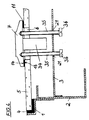
- the gas hob has a support frame 1 with a built-in housing 2 and cross members 3 mounted in the housing.
- a plate-shaped glass ceramic molded body 5 is inserted and provided with an edge seal 4, which can be designed as a sealing profile or injected sealing compound.
- the glass ceramic molded body 5 is provided with passages 6 for receiving a gas burner 7 in each case.
- the gas burners 7 are carried by the glass ceramic molded body, while the gas burners 7 have limited mobility with respect to the support frame 1, the housing 2 and the cross members 3.
- gas burners are provided on the top of the glass ceramic molded body 5 pot support 8, as indicated by dashed lines in Figure 1.
- the gas burner 7 is inserted into the passage 6 of the plate-shaped glass ceramic molded body 5 with a connection and sealing device 10 which is designed to be permanently elastic.
- the connecting and sealing device 10 has an upper, permanently elastic, flexible connecting and sealing element 11 and a lower, permanently elastic, flexible connecting and sealing element 12, both of which are designed in the form of flat sealing rings.
- the upper connecting and sealing element 11 is inserted on the top of the plate-shaped glass ceramic molded body 5 between the edge region 13 of the passage 6 and a connecting surface 14 formed on the gas burner 7.
- the lower connecting and sealing element 12 is inserted on the underside of the plate-shaped glass ceramic molded body 5 between the edge region 13 of the passage 6 and an annular or plate-shaped abutment element 15.
- a contact pressure of the connecting and sealing elements 11 and 12 against the edge region 13 of the passage 6 is desired and provided in such a way that the edge region 13 of the passage 6 is held gently but nonetheless resiliently and firmly between the two connecting and sealing elements and at the same time is effective Sealing against overcooked food, in particular liquid, on the upper side of the glass ceramic molded body 5 and on the connecting surface 14 of the gas burner 7 is ensured.
- this contact pressure is set in that the annular or plate-shaped abutment element 15 is held firmly on the gas burner 7 from below by means of a plurality of retaining pins 16 distributed all around.
- the distance of the abutment element 15 from the connection surface 14, which determines the contact pressure in connection with the thickness of the connecting and sealing elements 11, 12, is set by a spacer ring 17 inserted between the underside of the gas burner 7 and the abutment element 15 on each retaining pin 16.
- the retaining pins 16 are bolts with a bolt head 18.
- a washer 19 and a spacer tube 20 which is supported on the abutment element 15 are placed on the retaining pin 16 above the bolt head 18.
- the retaining pins 16 with the spacer tubes 20 extend from the abutment element 15 through bores 21 made in the cross member 3 to below the cross member 3, the bolt head 18 or at least the washer 19 having a larger diameter than the bore 21. Due to this arrangement and the fact that the gas burner 7 is connected to the valve device via flexible lines, there is limited mobility of the gas burner 7 with respect to the support frame 1 or the housing 2 and the crossmember 3. By thermal influence or by the weight of the pots placed and the like on the glass ceramic molded body 5 deformations are absorbed by this limited mobility, so that there is no tensioning of the Glass ceramic molded body 5 comes through the attachment of the gas burner 7.
- the gas burner 7 can only move downwards by the distance 22 of the abutment element 15 from the cross member 3. If the user of the hob wants to pull the gas burner 7 upwards when the glass ceramic molded body 5 breaks, this movement is limited by striking the washer 19 on the underside of the cross member 3. A lifting movement is thus only possible by the distance 23 between the cross member 3 and the washer 19. Both the lowering movement and the lifting movement can be absorbed by the flexible feed line to the gas burner 7 without endangering its connection with the gas burner 7 and the valve device (not shown). If the glass ceramic molded body 5 breaks, the gas burner 7 can only be rotated to the extent of the play that the spacer tube 20 has in the bore 21 of the cross member 3. Even with such a limited twist, the connections of the feed line to the burner 7 cannot be endangered.
- the basic structure of the hob is the same as that in the example in FIG. 1.
- the distance between the connecting surface 14 of the gas burner 7 and the abutment element 15, which determines the contact pressure of the connecting and sealing elements 11 and 12, is the gas burner 7 is formed on its underside with cylindrical projections 24 or a corresponding projection ring.
- the retaining pins 16 are in this example, retaining bolts with a stepped threaded section 25, so that they sit with their thicker bolt part 26 when screwing the threaded section 25 into the projections 24 from below against the abutment element 15 and fasten this on the underside of the projections 24 on the gas burner 7.
- the holding pins 16 have an enlarged, plate-shaped head 27; since the holding pins 16 extend downwards through bores 21 of the cross member 3 and their plate-shaped head 27 has a larger diameter than the bores 21, in the example of FIG. 2 the same movement limitation of the gas burner 7 with respect to the support frame 1 or the housing 2 and the Trusses 3 of the hob reached.
- the basic structure of the gas hob is identical to that of the hob according to FIG. 1.
- the connecting and sealing device 10 has a profile ring that unites both connecting and sealing elements to form a unit, which surrounds the edge region of the passage 6.
- the body of the gas burner 7 with its annular connecting surface is placed on the upper leg of this profile ring, while the abutment element 15 is pressed onto the lower leg of the profile ring 30 from below.
- the contact pressure of the upper leg of the profile ring 30 on the edge region 13 of the passage 6 and on the connecting surface 14 of the gas burner 7 is generated in this example by compression springs 31 which are inserted between the head 32 of each of the retaining pins 16 designed as screw bolts and the abutment element 15 .
- the threaded bores 33 in the body of the gas burner 7 are of sufficient length to be able to screw in the retaining pins 16 designed as screw bolts to a greater or lesser extent.
- the permanently elastic pressure exerted by the compression springs 31 on the underside of the abutment element 15 can be set in the body of the gas burner 7 depending on the screw-in depth of the retaining pins 16. Accordingly, the contact pressure of the upper leg of the profile ring 30 on the edge region 13 of the passage 6 in the glass ceramic molded body 5 and on the connecting surface 14 of the gas burner 7 will also be set.
- the gas burners 7 have limited mobility with respect to the support frame 1, the housing 2 and the crossmember 3. If the glass ceramic molded body 5 is omitted, for example broken, it can be provided Gas burners 7 drop down by such a degree until they meet the cross member 3 inside the housing 2 with a lower attachment 34 attached to them.
- the attachment 34 attached to the underside of the gas burner 7 thus forms an additional limitation for the downward movement of the gas burner 7, which becomes possible if the glass ceramic molded body 5 breaks or otherwise disappears.
- the upward movement of the gas burners 7 which becomes possible when the glass ceramic molded body 5 is omitted is limited by the heads 32 of the retaining pins 16, since these heads 32 are larger than the bores 21 in the cross member 3.
- a turning of the gas burner 7, which becomes possible when the glass ceramic molded body 5 is omitted, is very narrowly limited to the play of the holding pins 6 in the bores 21 of the crossmember 3. As in the examples of FIGS. 1 and 2, this limitation of any risk increases the connections of the feed lines to the gas burners 7 excluded.
- the profile rings 30 are inserted into the passages 6 of the glass ceramic molded body 5 before the gas burners 7 are inserted, possibly before the glass ceramic molded body 5 is inserted into the carrier frame 1. It is then only necessary to insert the gas burners 7 into the passages 6 and to place them with their connecting surface 14 on the upper side of the upper leg of the profile rings 30.
- the abutment element 15 is to be brought up from below, there are then only the retaining pins 16 with the compression springs 31 attached through the bores 21 of the cross member 3, from there to be inserted through the bores of the abutment element 15 and screwed into the threaded bores 33 in the body of the gas burner 7 at the desired depth.
- connection and sealing device in this example is considerably simplified in that only an upper connection and sealing element 11 is provided, which is flatter Sealing ring made of permanently resilient material is glued to the top of the glass ceramic molded body 5 in the edge region 13 of the passage 6.
- the connecting and sealing element 11 is also glued to the connecting surface 14 of the gas burner 7.
- the gas burner 7 is carried solely by the plate-shaped glass ceramic molded body 5. There is no further attachment of the gas burner 7 to the support frame 1, the housing 2 and the cross member 3.
- securing pins 35 are provided, which replace the retaining pins 16 provided in the exemplary embodiments according to FIGS. 1 to 3.
- the securing pins 35 are likewise screw bolts with heads 36 in the example shown and extend through Bores 21 in the cross member 3.
- the bores 21 are smaller than the heads 36 of the locking pins 35. Because of their play in the bores 21 of the cross member 3 and because their heads 36 extend downward beyond the cross member 3, the locking pins 35 do not form any fastening elements of the gas burner 7 on the support frame 1 or the housing 2 and the cross member 3.
- the gas burner 7 can move down a small amount until a lower shoulder 34 meets the cross member 3.
- An upward movement for example when attempting to lift the gas burner 7 out, is limited by the fact that the heads 36 of the securing pins 35 hit the cross member 3 from below.
- the movement is limited to the play of the locking pins 35 in the holes 21.
- a flexible connection line from the gas burner to the gas valve is protected and in particular also secured against the loosening of its connection points.
- the assembly of the gas burner 7 is particularly simple.
- the connecting and sealing element 11 can already be glued to the connecting surface 14 of the gas burner 7 before assembly.
- the bonding of the connecting and sealing element 11 to the edge region 13 of the passage must then be prepared and the gas burner 7 inserted and provided with the securing pins 35 inserted through the bores 21 of the cross member 3.
- the securing pins 35 can be attached before or together with the bonding of the connecting and sealing element 11 in the edge region 13 of the passage.
Landscapes
- Engineering & Computer Science (AREA)
- Chemical & Material Sciences (AREA)
- Combustion & Propulsion (AREA)
- Mechanical Engineering (AREA)
- General Engineering & Computer Science (AREA)
- Gas Burners (AREA)
- Glass Melting And Manufacturing (AREA)
- Waste-Gas Treatment And Other Accessory Devices For Furnaces (AREA)
Applications Claiming Priority (2)
| Application Number | Priority Date | Filing Date | Title |
|---|---|---|---|
| DE4133409 | 1991-10-09 | ||
| DE4133409A DE4133409C2 (de) | 1991-10-09 | 1991-10-09 | Brenneranordnung |
Publications (2)
| Publication Number | Publication Date |
|---|---|
| EP0536619A1 true EP0536619A1 (fr) | 1993-04-14 |
| EP0536619B1 EP0536619B1 (fr) | 1995-03-01 |
Family
ID=6442325
Family Applications (1)
| Application Number | Title | Priority Date | Filing Date |
|---|---|---|---|
| EP92116602A Expired - Lifetime EP0536619B1 (fr) | 1991-10-09 | 1992-09-29 | Montage d'au moins un brûleur à gaz dans un corp en matière fragile, par exemple dans une plaque de cuisson |
Country Status (8)
| Country | Link |
|---|---|
| US (1) | US5313929A (fr) |
| EP (1) | EP0536619B1 (fr) |
| JP (1) | JP2909859B2 (fr) |
| AT (1) | ATE119264T1 (fr) |
| CA (1) | CA2080170A1 (fr) |
| DE (2) | DE4133409C2 (fr) |
| ES (1) | ES2069951T3 (fr) |
| GR (1) | GR3015874T3 (fr) |
Cited By (5)
| Publication number | Priority date | Publication date | Assignee | Title |
|---|---|---|---|---|
| EP0905451A1 (fr) * | 1997-09-27 | 1999-03-31 | Schott Glas | Agencement d'un brûleur atmosphérique dans une plaque de cuisson en vitro-céramique |
| DE19820444A1 (de) * | 1998-05-07 | 1999-11-11 | Bsh Bosch Siemens Hausgeraete | Federnde Gas-Brenner-Lagerung |
| EP0964203A1 (fr) * | 1998-06-09 | 1999-12-15 | SABAF S.p.A. | Brûleur à gaz |
| EP2696143A3 (fr) * | 2012-08-06 | 2014-08-20 | BSH Bosch und Siemens Hausgeräte GmbH | Plaque de cuisson avec élément d'étanchéité |
| EP2960581A1 (fr) * | 2014-06-25 | 2015-12-30 | BSH Hausgeräte GmbH | Dispositif de positionnement, plaque de cuisson et cuisiniere |
Families Citing this family (24)
| Publication number | Priority date | Publication date | Assignee | Title |
|---|---|---|---|---|
| DE4442572C1 (de) * | 1994-11-30 | 1995-09-28 | Schott Glaswerke | Vorrichtung zum Schutz der Ränder von Öffnungen in Formenkörpern aus Glaskeramik, Glas oder Keramik |
| US5640947A (en) * | 1995-02-15 | 1997-06-24 | Shute; Alan B. | Counter-top cooking unit using natural stone |
| FR2735562B1 (fr) * | 1995-06-19 | 1997-08-14 | Eurokera | Plaque de cuisson au gaz en vitroceramique et procede pour sa fabrication |
| US5628302A (en) * | 1995-06-21 | 1997-05-13 | Maytag Corporation | Burner assembly and pan seal |
| FR2763583B1 (fr) * | 1997-05-20 | 1999-07-09 | Eurokera | Plaque vitroceramique et son procede de fabrication |
| DE19733242C1 (de) * | 1997-08-01 | 1998-10-15 | Schott Glas | Gas-Kochfeld mit einem plattenförmigen Formkörper aus sprödbrüchigem Material |
| DE19746845C1 (de) * | 1997-10-23 | 1998-12-03 | Schott Glas | Anordnung eines keramischen Heizelementes als Kochzone in einer Aussparung einer Fläche |
| DE19813691C1 (de) | 1998-03-27 | 1999-06-10 | Schott Glas | Kochmulde mit einem Gasbrenner |
| DE19819732C1 (de) * | 1998-05-02 | 1999-08-26 | Schott Glas | Anordnung zur Befestigung eines atmosphärischen Gasbrenners an der Brenneröffnung einer Kochfläche aus Glas oder Glaskeramik sowie Kochfeld mit einer solchen Anordnung |
| DE19844551C2 (de) * | 1998-09-29 | 2001-04-26 | Schott Glas | Gaskochgerät |
| DE19905670A1 (de) * | 1998-12-16 | 2000-09-07 | Schott Glas | Kochgerät |
| GB9902804D0 (en) * | 1999-02-10 | 1999-03-31 | Trianco Redfyre | Heating plate levelling method |
| US6173708B1 (en) | 1999-11-15 | 2001-01-16 | Maytag Corporation | Gas burner mounting assembly for appliance with ceramic based cooktop |
| JP4520592B2 (ja) * | 2000-07-19 | 2010-08-04 | 株式会社ハーマンプロ | ガスコンロ |
| US6807962B2 (en) * | 2002-01-28 | 2004-10-26 | Schott Glas | Kitchen gas cooking stove with a glass-ceramic, glass, or ceramic top, a gas cooktop with a glass-ceramic, glass, or ceramic top, and a glass-ceramic, glass, or ceramic top of a cooking stove or cooktop with a venting structure thereon |
| ITUD20020141A1 (it) * | 2002-06-25 | 2003-12-29 | Commital Sami Spa | Bruciatore a gas |
| US6817355B1 (en) | 2003-06-13 | 2004-11-16 | Maytag Corporation | Gas burner mounting assembly for a cooking appliance having a ceramic-based cooktop |
| US20070044788A1 (en) * | 2005-08-26 | 2007-03-01 | Wacker Chemical Corporation | Method for mounting ceramic cooktops in appliance |
| NL2003212C2 (nl) * | 2009-07-16 | 2011-01-18 | Rvs Werken B V | Brandermodule voor een fornuis, een fornuis en werkwijze voor het vervaardigen daarvan. |
| ES2390715A1 (es) * | 2009-09-09 | 2012-11-15 | Bsh Electrodomésticos España, S.A. | Campo de coccion a gas y cocina de gas con campo de coccion a gas de tal tipo |
| EP2295867A3 (fr) | 2009-09-09 | 2017-12-06 | BSH Hausgeräte GmbH | Plaque de cuisson à gaz et cuisinière à gaz dotée d'une plaque de cuisson à gaz correspondante |
| JP5302237B2 (ja) * | 2010-02-10 | 2013-10-02 | リンナイ株式会社 | プレート式バーナ |
| CN114216137B (zh) * | 2021-12-13 | 2024-02-13 | 重庆维格家具有限公司 | 一种智能化家具及其控制系统 |
| CN119223533B (zh) * | 2024-12-03 | 2025-03-04 | 烟台裕峰专用机械设备有限公司 | 一种燃烧器的气密性检测设备 |
Citations (2)
| Publication number | Priority date | Publication date | Assignee | Title |
|---|---|---|---|---|
| DE2127555A1 (de) * | 1971-06-03 | 1972-12-14 | Siemens-Electrogeräte GmbH, 1000 Berlin u. 8000 München | Kochmulde mit einem Träger aus Glas, Glaskeramik oder Asbestzement |
| GB2149089A (en) * | 1983-11-03 | 1985-06-05 | Thorn Emi Domestic Appliances | Gas cooking hob |
Family Cites Families (2)
| Publication number | Priority date | Publication date | Assignee | Title |
|---|---|---|---|---|
| US4971024A (en) * | 1990-02-06 | 1990-11-20 | New World Domestic Appliances Limited | Cooking hobs |
| US5046477A (en) * | 1990-12-28 | 1991-09-10 | Amana Refrigeration Inc. | Gas cook-top with glass top |
-
1991
- 1991-10-09 DE DE4133409A patent/DE4133409C2/de not_active Expired - Fee Related
-
1992
- 1992-09-29 AT AT92116602T patent/ATE119264T1/de not_active IP Right Cessation
- 1992-09-29 EP EP92116602A patent/EP0536619B1/fr not_active Expired - Lifetime
- 1992-09-29 ES ES92116602T patent/ES2069951T3/es not_active Expired - Lifetime
- 1992-09-29 DE DE59201531T patent/DE59201531D1/de not_active Expired - Fee Related
- 1992-10-07 JP JP4291989A patent/JP2909859B2/ja not_active Expired - Lifetime
- 1992-10-08 CA CA002080170A patent/CA2080170A1/fr not_active Abandoned
- 1992-10-09 US US07/958,261 patent/US5313929A/en not_active Expired - Fee Related
-
1995
- 1995-04-19 GR GR950401004T patent/GR3015874T3/el unknown
Patent Citations (2)
| Publication number | Priority date | Publication date | Assignee | Title |
|---|---|---|---|---|
| DE2127555A1 (de) * | 1971-06-03 | 1972-12-14 | Siemens-Electrogeräte GmbH, 1000 Berlin u. 8000 München | Kochmulde mit einem Träger aus Glas, Glaskeramik oder Asbestzement |
| GB2149089A (en) * | 1983-11-03 | 1985-06-05 | Thorn Emi Domestic Appliances | Gas cooking hob |
Cited By (7)
| Publication number | Priority date | Publication date | Assignee | Title |
|---|---|---|---|---|
| EP0905451A1 (fr) * | 1997-09-27 | 1999-03-31 | Schott Glas | Agencement d'un brûleur atmosphérique dans une plaque de cuisson en vitro-céramique |
| US6032662A (en) * | 1997-09-27 | 2000-03-07 | Schott Glas | Cooktop apparatus |
| DE19820444A1 (de) * | 1998-05-07 | 1999-11-11 | Bsh Bosch Siemens Hausgeraete | Federnde Gas-Brenner-Lagerung |
| EP0961081B1 (fr) * | 1998-05-07 | 2002-11-27 | BSH Bosch und Siemens Hausgeräte GmbH | Palier à ressort pour brûleur à gaz |
| EP0964203A1 (fr) * | 1998-06-09 | 1999-12-15 | SABAF S.p.A. | Brûleur à gaz |
| EP2696143A3 (fr) * | 2012-08-06 | 2014-08-20 | BSH Bosch und Siemens Hausgeräte GmbH | Plaque de cuisson avec élément d'étanchéité |
| EP2960581A1 (fr) * | 2014-06-25 | 2015-12-30 | BSH Hausgeräte GmbH | Dispositif de positionnement, plaque de cuisson et cuisiniere |
Also Published As
| Publication number | Publication date |
|---|---|
| US5313929A (en) | 1994-05-24 |
| DE4133409A1 (de) | 1993-04-15 |
| DE59201531D1 (de) | 1995-04-06 |
| DE4133409C2 (de) | 1993-10-21 |
| ATE119264T1 (de) | 1995-03-15 |
| CA2080170A1 (fr) | 1993-04-10 |
| EP0536619B1 (fr) | 1995-03-01 |
| JP2909859B2 (ja) | 1999-06-23 |
| JPH06193839A (ja) | 1994-07-15 |
| ES2069951T3 (es) | 1995-05-16 |
| GR3015874T3 (en) | 1995-07-31 |
Similar Documents
| Publication | Publication Date | Title |
|---|---|---|
| EP0536619B1 (fr) | Montage d'au moins un brûleur à gaz dans un corp en matière fragile, par exemple dans une plaque de cuisson | |
| EP0592847B1 (fr) | Dispositif pour fixer une plaque rigide à une embase de fixation | |
| EP0905451B1 (fr) | Brûleur atmosphérique dans une plaque de cuisson en vitro-céramique | |
| DE69514007T2 (de) | Sprinklerkopf | |
| EP2614002B1 (fr) | Dispositif de fixation | |
| DE3613901A1 (de) | Strahlheizkoerper fuer kochgeraete oder dgl. | |
| DE4446017A1 (de) | Bremsscheibe, insbesondere innenbelüftete Bremsscheibe | |
| DE102019004829A1 (de) | Stützsystem zum Tragen eines Teils eines Bauwerks | |
| DE2744036B2 (de) | Vorrichtung zum Befestigen einer Dacheindeckungsplatte | |
| EP2295868B1 (fr) | Plaque de cuisson à gaz et gazinière dotée d'une plaque de cuisson à gaz correspondante | |
| DE29702649U1 (de) | Gasbrenner für flache Kochmulden | |
| DE3811401C2 (fr) | ||
| DE19733242C1 (de) | Gas-Kochfeld mit einem plattenförmigen Formkörper aus sprödbrüchigem Material | |
| DE19951652A1 (de) | Vormontierte Befestigungsschraube | |
| DE29815492U1 (de) | Verbessertes Schraubelement | |
| EP2407675B1 (fr) | Appareil ménager doté d'une plaque de recouvrement et d'un boîtier placé sous la plaque de recouvrement ainsi que procédé de positionnement d'une équerre de fixation sur un boîtier placé sous la plaque de recouvrement d'un appareil ménager | |
| DE29717322U1 (de) | Anordnung eines atmosphärischen Gasbrenners in einer Kochmulde mit einer Kochfläche aus Glaskeramik | |
| EP1366644A1 (fr) | Ensemble plaque de travail | |
| DE102017111417B4 (de) | Punkthalter | |
| DE4241368C2 (de) | Tragkörper für Sitzschienen von Fahrzeugsitzen, insbesondere Kraftfahrzeugsitzen und Verfahren zum Einbau eines Fahrzeugsitzes in ein Fahrzeug unter Verwendung solcher Tragkörper | |
| EP0752508A2 (fr) | Couverture de façade | |
| DE514363C (de) | Kochgefaess mit einem den Bodenteil umgebenden Heizmantel | |
| EP0667462B1 (fr) | Colonne réglable pour sièges, tables ou similaires et agrafe de fixation | |
| DD298153A5 (de) | Vorrichtung zur abstuetzung von maschinen od. dgl. | |
| DE3018016A1 (de) | Agraffe zur befestigung eines fassadenelements |
Legal Events
| Date | Code | Title | Description |
|---|---|---|---|
| PUAI | Public reference made under article 153(3) epc to a published international application that has entered the european phase |
Free format text: ORIGINAL CODE: 0009012 |
|
| AK | Designated contracting states |
Kind code of ref document: A1 Designated state(s): AT BE DE ES FR GB GR IT LU NL |
|
| 17P | Request for examination filed |
Effective date: 19930511 |
|
| 17Q | First examination report despatched |
Effective date: 19940121 |
|
| GRAA | (expected) grant |
Free format text: ORIGINAL CODE: 0009210 |
|
| AK | Designated contracting states |
Kind code of ref document: B1 Designated state(s): AT BE DE ES FR GB GR IT LU NL |
|
| REF | Corresponds to: |
Ref document number: 119264 Country of ref document: AT Date of ref document: 19950315 Kind code of ref document: T |
|
| ET | Fr: translation filed | ||
| GBT | Gb: translation of ep patent filed (gb section 77(6)(a)/1977) |
Effective date: 19950307 |
|
| REF | Corresponds to: |
Ref document number: 59201531 Country of ref document: DE Date of ref document: 19950406 |
|
| ITF | It: translation for a ep patent filed | ||
| REG | Reference to a national code |
Ref country code: ES Ref legal event code: FG2A Ref document number: 2069951 Country of ref document: ES Kind code of ref document: T3 |
|
| REG | Reference to a national code |
Ref country code: GR Ref legal event code: FG4A Free format text: 3015874 |
|
| PLBE | No opposition filed within time limit |
Free format text: ORIGINAL CODE: 0009261 |
|
| 26N | No opposition filed | ||
| PGFP | Annual fee paid to national office [announced via postgrant information from national office to epo] |
Ref country code: GB Payment date: 19980814 Year of fee payment: 7 |
|
| PGFP | Annual fee paid to national office [announced via postgrant information from national office to epo] |
Ref country code: FR Payment date: 19980821 Year of fee payment: 7 Ref country code: DE Payment date: 19980821 Year of fee payment: 7 |
|
| PGFP | Annual fee paid to national office [announced via postgrant information from national office to epo] |
Ref country code: AT Payment date: 19980824 Year of fee payment: 7 |
|
| PGFP | Annual fee paid to national office [announced via postgrant information from national office to epo] |
Ref country code: LU Payment date: 19980825 Year of fee payment: 7 |
|
| PGFP | Annual fee paid to national office [announced via postgrant information from national office to epo] |
Ref country code: NL Payment date: 19980827 Year of fee payment: 7 |
|
| PGFP | Annual fee paid to national office [announced via postgrant information from national office to epo] |
Ref country code: GR Payment date: 19980831 Year of fee payment: 7 |
|
| PGFP | Annual fee paid to national office [announced via postgrant information from national office to epo] |
Ref country code: BE Payment date: 19980908 Year of fee payment: 7 |
|
| PGFP | Annual fee paid to national office [announced via postgrant information from national office to epo] |
Ref country code: ES Payment date: 19980925 Year of fee payment: 7 |
|
| PG25 | Lapsed in a contracting state [announced via postgrant information from national office to epo] |
Ref country code: LU Free format text: LAPSE BECAUSE OF NON-PAYMENT OF DUE FEES Effective date: 19990929 Ref country code: GB Free format text: LAPSE BECAUSE OF NON-PAYMENT OF DUE FEES Effective date: 19990929 Ref country code: AT Free format text: LAPSE BECAUSE OF NON-PAYMENT OF DUE FEES Effective date: 19990929 |
|
| PG25 | Lapsed in a contracting state [announced via postgrant information from national office to epo] |
Ref country code: GR Free format text: LAPSE BECAUSE OF NON-PAYMENT OF DUE FEES Effective date: 19990930 Ref country code: ES Free format text: LAPSE BECAUSE OF NON-PAYMENT OF DUE FEES Effective date: 19990930 Ref country code: BE Free format text: LAPSE BECAUSE OF NON-PAYMENT OF DUE FEES Effective date: 19990930 |
|
| BERE | Be: lapsed |
Owner name: SCHOTT GLASWERKE Effective date: 19990930 |
|
| PG25 | Lapsed in a contracting state [announced via postgrant information from national office to epo] |
Ref country code: NL Free format text: LAPSE BECAUSE OF NON-PAYMENT OF DUE FEES Effective date: 20000401 |
|
| GBPC | Gb: european patent ceased through non-payment of renewal fee |
Effective date: 19990929 |
|
| PG25 | Lapsed in a contracting state [announced via postgrant information from national office to epo] |
Ref country code: FR Free format text: LAPSE BECAUSE OF NON-PAYMENT OF DUE FEES Effective date: 20000531 |
|
| NLV4 | Nl: lapsed or anulled due to non-payment of the annual fee |
Effective date: 20000401 |
|
| PG25 | Lapsed in a contracting state [announced via postgrant information from national office to epo] |
Ref country code: DE Free format text: LAPSE BECAUSE OF NON-PAYMENT OF DUE FEES Effective date: 20000801 |
|
| REG | Reference to a national code |
Ref country code: FR Ref legal event code: ST |
|
| REG | Reference to a national code |
Ref country code: ES Ref legal event code: FD2A Effective date: 20001013 |
|
| PG25 | Lapsed in a contracting state [announced via postgrant information from national office to epo] |
Ref country code: IT Free format text: LAPSE BECAUSE OF NON-PAYMENT OF DUE FEES;WARNING: LAPSES OF ITALIAN PATENTS WITH EFFECTIVE DATE BEFORE 2007 MAY HAVE OCCURRED AT ANY TIME BEFORE 2007. THE CORRECT EFFECTIVE DATE MAY BE DIFFERENT FROM THE ONE RECORDED. Effective date: 20050929 |