EP0536632A1 - Machine à cintrer les tubes avec un mécanisme auxiliaire pour effectuer des opérations supplémentaires - Google Patents
Machine à cintrer les tubes avec un mécanisme auxiliaire pour effectuer des opérations supplémentaires Download PDFInfo
- Publication number
- EP0536632A1 EP0536632A1 EP92116714A EP92116714A EP0536632A1 EP 0536632 A1 EP0536632 A1 EP 0536632A1 EP 92116714 A EP92116714 A EP 92116714A EP 92116714 A EP92116714 A EP 92116714A EP 0536632 A1 EP0536632 A1 EP 0536632A1
- Authority
- EP
- European Patent Office
- Prior art keywords
- bending machine
- pipe
- shaft
- clamp
- cam follower
- Prior art date
- Legal status (The legal status is an assumption and is not a legal conclusion. Google has not performed a legal analysis and makes no representation as to the accuracy of the status listed.)
- Granted
Links
Images



Classifications
-
- B—PERFORMING OPERATIONS; TRANSPORTING
- B21—MECHANICAL METAL-WORKING WITHOUT ESSENTIALLY REMOVING MATERIAL; PUNCHING METAL
- B21D—WORKING OR PROCESSING OF SHEET METAL OR METAL TUBES, RODS OR PROFILES WITHOUT ESSENTIALLY REMOVING MATERIAL; PUNCHING METAL
- B21D41/00—Application of procedures in order to alter the diameter of tube ends
- B21D41/02—Enlarging
- B21D41/026—Enlarging by means of mandrels
-
- B—PERFORMING OPERATIONS; TRANSPORTING
- B21—MECHANICAL METAL-WORKING WITHOUT ESSENTIALLY REMOVING MATERIAL; PUNCHING METAL
- B21D—WORKING OR PROCESSING OF SHEET METAL OR METAL TUBES, RODS OR PROFILES WITHOUT ESSENTIALLY REMOVING MATERIAL; PUNCHING METAL
- B21D41/00—Application of procedures in order to alter the diameter of tube ends
- B21D41/02—Enlarging
- B21D41/025—Enlarging by means of impact-type swaging hand tools
Definitions
- the present invention relates to a bending machine for metal pipes and similar linear elements.
- the pipes can be of circular or polygonal cross-section.
- Other linear elements which can be bent by the machine include for example metal sections.
- Such bending machines are used both at the craftsman and industrial level for the most varied uses, including the formation of heat transfer coils, the production of metal furniture or metal structures in general, and in industrial heating, sanitary and electrical systems.
- a particularly versatile bending machine which enables a mechanical workshop to satisfy the most varied pipe and metal section bending requirements is that described in utility model patent No. 213 444.
- This bending machine besides possessing the basic requirement of not deforming the pipe cross-section during bending and of being easily operated with one hand, is able to form bends of both of very small and very large radius of curvature, to form several successive bends with a very small space between them, to adapt to the various diameters and dimensions of commercially available pipes and sections, and form bends having an angle of curvature of 180° and more.
- the aforesaid bending machine comprises a box casing in which a die shaft is rotated manually, or by an electric motor via a step-down gear.
- the bending machine is provided with a pipe presser shoe shaped to adapt to part of the outline of the cross-section of the element to be bent, this shoe being movable towards the element to be bent and away from it to lock it before operating the bending machine.
- this bending machine can be made small and lightweight compared with other bending machines, so enabling it to be easily moved by an operator without particular strength, it still has to be fixed to a stand, workbench or the like for operation.
- the stand or workbench cannot always be located in the optimum position for using the bending machine, either because of space considerations or because of the position or height at which the work has to be carried out, or for other reasons. This means that the operator has to carry the element to be bent from its location to the position in which the bending machine is located, with a considerable loss of time.
- This bending machine comprises an electric drive motor, a casing, and a die shaft with die, supported rotatably by the casing and operable by a gear train for transmitting rotary motion from the motor to the die with speed step-down.
- Means are provided for gripping the bending machine with only one hand and means for controlling the operation of the motor using the actual hand gripping the bending machine.
- the bending machine is at least partly formed of aluminium and/or light alloy and/or plastics material.
- the bending machine can be used by gripping it with only one hand, and therefore enables a pipe or similar linear element to be bent in any position, including for example on a ladder or where space problems do not allow a stand to be positioned.
- the bending machine can however obviously be provided likewise with means for fixing it to a conventional support if this is required, for example for repetitive work or work to be done offsite or in the workshop.
- the electric drive motor is a gun-type drill motor.
- the gear train is contained in a bending unit of which said casing forms part. Means are also provided for connecting said drill to the casing, and means for transmitting the movement of the drill chuck to said gear train.
- the casing and all other suitable parts of the bending machine are constructed of aluminium and/or light alloy and/or suitable plastics material. This reduces the weight of the bending machine to a truly minimum level, to achieve maximum manageability with minimum effort by the user.
- the object of the present invention is to provide a bending machine of the type comprising a motorized shaft which is able to perform supplementary operations of the aforesaid type without the need to remove the die from the bending machine.
- the bending machine according to the present invention characterised by comprising an auxiliary mechanism for transforming the rotary movement of said motorized shaft into a reciprocating movement for operating additional devices which form part of the bending machine or can be fitted thereto for performing supplementary operations.
- its operation as a bending machine is made independent of the performing of supplementary operations, so that the machine of the present invention can be used in either mode without having to replace the die with the mechanism in order to perform said supplementary operations.
- said motorized shaft of the bending machine comprises parallel to the shaft axis an eccentric portion of circular cross-section, and is provided with a cam follower movable only in a direction perpendicular to the axis of the eccentric portion. In this manner the rotary movement of said motorized shaft is transformed into a reciprocating movement suitable for operating said additional devices.
- this transformation is achieved by the motorized shaft operating a connecting rod/crank mechanism.
- Said additional devices operated by the reciprocating movement obtained by said auxiliary mechanism, are preferably devices for widening or flanging pipe ends, or for punching pipes or metal sheets.
- said cam follower conveniently comprises a coaxial conical point to be inserted into a seat provided in a cylindrical unit coaxial to said point, said cylindrical unit being formed from several wedge elements which move radially following the insertion of the point into its seat.
- the clamp can comprise a plurality of seats for receiving pipes of various diameters.
- the punch can also be of the type suitable for punching pipes or metal sheets, these latter being retained in position during punching by a suitable clamp connectable to the bending machine.
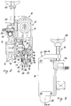
- the bending machine 10 is composed basically of a conventional drill 14 of gun type, connectable to a bending unit 12.
- This latter consists of a casing 16 comprising a recess ( Figure 4) into which said drill 14 is inserted.
- Means 23, 24 are provided for transmitting the rotary movement of the drill chuck 20 to a gear train 30/34, 42/44, 52/54, 66/68 which transmits the rotary movement of the electric motor of the drill 14 with speed step-down to rotate a die 74, into the groove 96 of which the pipe 98 to be bent is inserted.
- a pipe pressing shoe 104 shaped to fit part of the contour of the cross-section through the pipe 98 and fixed to the clamp 102, can be moved by the handwheel 100 both away from and towards the pipe 98 to lock it before operating the bending machine.
- the operation of the bending machine 10 is controlled by the trigger 92 on the handgrip 13 ( Figure 3) of the drill 14.
- a first auxiliary mechanism is shown in Figures 1, 2 and 4 and consists essentially of an eccentric extension 86 of the shaft 70, said extension having a circular cross-section.
- the upper end of a pin 88 which acts as a guide for a return spring 90, always remains in contact with the surface of the eccentric extension 86. Consequently ( Figure 4), when the drill 14 is operated by pressing the trigger 92, the rotary movement of the chuck 20 is transmitted via the gear train 30/34, 42/44, 52/54, 66/68 to the shaft 80, so that the pin 88 ( Figure 2) moves with reciprocating movement in the direction of its axis.
- the pin 88 is guided by a bush 120 (Figure 3) inserted into a hole 124 provided in the casing 16.
- Said bush 120 consists of two coaxial cylindrical parts, both threaded.
- a nut 120 is screwed onto the smaller-diameter part of the bush 120 ( Figure 4) to lock it in position.
- the pin 88 has a conically pointed lower end 106.
- This latter assumed to be in the position shown in Figure 2, is pushed downwards on operating the drill 14, to operate a device which in this specific case enables pipe ends to be widened.
- This additional device consists of four wedges 108 (see also Figure 5) which are urged radially outwards when the point 106 on being lowered becomes inserted between the wedges 108.
- Each wedge 108 is provided with a fin 116 positioned between an outer circular wall 112 and an inner circular wall 114 of a retaining bush 110 screwed onto the larger-diameter outer part of the bush 120.
- the fin 116 and the circular walls 112 and 114 enable the wedges 108 to be correctly guided in their radial movement. If on the outwardly projecting part of the wedge assembly 108, which forms an overall cylindrical projection, a pipe of diameter just greater than this cylindrical part is mounted, the lowering movement of the point 106 will cause the end of the pipe to undergo a radially outward force. If this force exceeds the elastic limit of the constituent material of the pipe, said pipe end will be widened by the end of the operation, ie it will have a diameter greater than its original diameter. This enables a so-called socket joint to be formed between said widened end and the end of another pipe which has not undergone this operation.
- Figures 3 and 4 do not comprise the described additional device, which is removable by simply unscrewing the bush 110. It is replaced by a rounded protection bush 118, fitted when the additional device is not to be used.
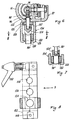
- Figure 6 shows an auxiliary mechanism slightly different from that heretofore described.
- the upper end of the pin 88' is maintained constantly resting against the surface of the eccentric extension 86 by the return spring 90, so that it moves with reciprocating movement when the drill 14 is operated.
- a punch 124 lowerly of frusto-conical shape is fixed to the lower end of the pin 88' by conventional means, clearly visible in Figure 6.
- a holder 126 comprising a threaded circular hole 128 in its top is screwed tightly onto the bush 120 as shown in Figure 6.
- the two lower arms 130 of the holder 126 are arranged to receive and support a bar-shaped clamp 132, better seen in Figures 8 and 9.
- the clamp 132 comprises a series of through holes of different diameter and can be moved longitudinally within the holder 126 to enable each hole 134, 136, 138 to be centered below the punch 124. The centering of these holes is facilitated by the presence of suitable locator steps 140, 142, 144 and 146 provided on the lower side of the clamp 132 ( Figure 9).
- the clamp 132 is divided longitudinally into two parts ( Figure 8) hinged together by a hinge 148 so that the clamp 132 can be opened to insert the pipe to be widened or flanged into the relative hole.
- the holes 134, 136, 138 are of diameters to match pipes of commonly used standard diameters, so that the pipe becomes locked in position when the clamp 132 is closed.
- the clamp can be locked in its closed position by a conventional snap handle 150 ( Figure 8).
- the additional device shown in Figure 6 enables a flared flange to be formed at the end of a pipe 98' locked in the clamp 132, as a result of the descent of the punch 124 (its lowest position is indicated by a dashed and dotted line in Figure 6).
- Figure 7 shows a further additional device to be fitted to the bending machine 10' to obtain a flat flange at the end of a pipe 98'' starting from a flared flange previously formed by the device of Figure 6.
- the punch 124' has the shape shown in Figure 7. The operation of the device is obvious and does not require further comment.
- Figure 10 shows a further additional device to be fitted to the bending machine 10' for widening the end of a pipe 98'''.
- the punch 124'' has the shape shown in Figure 10. The operation of the device is again obvious from this figure, and does not require further comment.
- auxiliary mechanism the purpose of which is to transform the rotary movement of the shaft 70 into reciprocating movement of a pin 88, 88', can also be formed in other ways, for example by a connecting rod/crank mechanism.
Landscapes
- Engineering & Computer Science (AREA)
- Mechanical Engineering (AREA)
- Bending Of Plates, Rods, And Pipes (AREA)
- Perforating, Stamping-Out Or Severing By Means Other Than Cutting (AREA)
- Earth Drilling (AREA)
Applications Claiming Priority (2)
| Application Number | Priority Date | Filing Date | Title |
|---|---|---|---|
| ITRE910065 | 1991-10-09 | ||
| ITRE910065A IT1252748B (it) | 1991-10-09 | 1991-10-09 | Macchina curvatrice per tubi con meccanismo ausiliario per l' esecuzione di operazioni ausiliarie. |
Publications (2)
| Publication Number | Publication Date |
|---|---|
| EP0536632A1 true EP0536632A1 (fr) | 1993-04-14 |
| EP0536632B1 EP0536632B1 (fr) | 1995-11-08 |
Family
ID=11398067
Family Applications (1)
| Application Number | Title | Priority Date | Filing Date |
|---|---|---|---|
| EP92116714A Expired - Lifetime EP0536632B1 (fr) | 1991-10-09 | 1992-09-30 | Machine à cintrer les tubes avec un mécanisme auxiliaire pour effectuer des opérations supplémentaires |
Country Status (4)
| Country | Link |
|---|---|
| EP (1) | EP0536632B1 (fr) |
| DE (1) | DE69205940T2 (fr) |
| ES (1) | ES2082314T3 (fr) |
| IT (1) | IT1252748B (fr) |
Cited By (1)
| Publication number | Priority date | Publication date | Assignee | Title |
|---|---|---|---|---|
| ITBI20080014A1 (it) * | 2008-07-31 | 2010-02-01 | Mauro Passadore | Curvatubi compatta applicabile ad elletroutensili. |
Citations (6)
| Publication number | Priority date | Publication date | Assignee | Title |
|---|---|---|---|---|
| GB121705A (en) * | 1918-07-25 | 1919-01-02 | Greenwood And Batley Ltd | Improvements in Machines for Bulging the Ends of Tubes. |
| GB509188A (en) * | 1937-05-28 | 1939-07-12 | Mannesmann Ag | Process and apparatus for expanding tubes |
| EP0004858A2 (fr) * | 1978-04-24 | 1979-10-31 | L. ID. IT dei F.lli Belotti | Appareil pour cintrer des tubes |
| FR2478498A2 (fr) * | 1980-03-18 | 1981-09-25 | Lepriol Rene | Appareil a faconner les extremites de tubes pour leur raccordement |
| FR2483271A1 (fr) * | 1980-05-28 | 1981-12-04 | Gateau Internal | Appareil de faconnage de tubes |
| DE3925950A1 (de) * | 1989-08-05 | 1991-02-07 | Woerlein Randolph | Rohrbiegemaschine |
-
1991
- 1991-10-09 IT ITRE910065A patent/IT1252748B/it active IP Right Grant
-
1992
- 1992-09-30 EP EP92116714A patent/EP0536632B1/fr not_active Expired - Lifetime
- 1992-09-30 DE DE69205940T patent/DE69205940T2/de not_active Expired - Lifetime
- 1992-09-30 ES ES92116714T patent/ES2082314T3/es not_active Expired - Lifetime
Patent Citations (6)
| Publication number | Priority date | Publication date | Assignee | Title |
|---|---|---|---|---|
| GB121705A (en) * | 1918-07-25 | 1919-01-02 | Greenwood And Batley Ltd | Improvements in Machines for Bulging the Ends of Tubes. |
| GB509188A (en) * | 1937-05-28 | 1939-07-12 | Mannesmann Ag | Process and apparatus for expanding tubes |
| EP0004858A2 (fr) * | 1978-04-24 | 1979-10-31 | L. ID. IT dei F.lli Belotti | Appareil pour cintrer des tubes |
| FR2478498A2 (fr) * | 1980-03-18 | 1981-09-25 | Lepriol Rene | Appareil a faconner les extremites de tubes pour leur raccordement |
| FR2483271A1 (fr) * | 1980-05-28 | 1981-12-04 | Gateau Internal | Appareil de faconnage de tubes |
| DE3925950A1 (de) * | 1989-08-05 | 1991-02-07 | Woerlein Randolph | Rohrbiegemaschine |
Cited By (1)
| Publication number | Priority date | Publication date | Assignee | Title |
|---|---|---|---|---|
| ITBI20080014A1 (it) * | 2008-07-31 | 2010-02-01 | Mauro Passadore | Curvatubi compatta applicabile ad elletroutensili. |
Also Published As
| Publication number | Publication date |
|---|---|
| EP0536632B1 (fr) | 1995-11-08 |
| DE69205940T2 (de) | 1996-06-20 |
| IT1252748B (it) | 1995-06-28 |
| ITRE910065A0 (it) | 1991-10-09 |
| ITRE910065A1 (it) | 1993-04-09 |
| DE69205940D1 (de) | 1995-12-14 |
| ES2082314T3 (es) | 1996-03-16 |
Similar Documents
| Publication | Publication Date | Title |
|---|---|---|
| US5174004A (en) | Radiator clamping jig | |
| US5806362A (en) | Method and apparatus for carrying out an operation on a mechanical workpiece | |
| EP1064124B1 (fr) | Appareil permettant de perforer les charpentes d'acier | |
| EP0318419B1 (fr) | Mandrin pour machine à fileter | |
| WO1996031319A9 (fr) | Procede et appareil pour effectuer une operation sur une piece mecanique | |
| EP0133952A1 (fr) | Outil manuel pour élargir des tuyaux | |
| EP0536632A1 (fr) | Machine à cintrer les tubes avec un mécanisme auxiliaire pour effectuer des opérations supplémentaires | |
| US9701036B2 (en) | Hand tool for punching sheet material | |
| US5626045A (en) | Metal stock bender | |
| US7150175B2 (en) | Clamp assembly for bend arm of tube bending machine | |
| CA1109777A (fr) | Dispositif manuel de sertissage | |
| US4428216A (en) | Tube bender | |
| US7836743B1 (en) | System and method for material bending | |
| CN208575187U (zh) | 一种蛇骨压制夹具 | |
| US5495739A (en) | Apparatus for forming scrolls from strip material | |
| US5709117A (en) | Collet assembly for bending apparatus | |
| CN217617041U (zh) | 一种多功能弯管器 | |
| EP0690754B1 (fr) | Outil a main servant a elargir une extremite de tuyau | |
| EP0630299B1 (fr) | Mecanisme de blocage d'une tige et son procede de fabrication | |
| CN118043150A (zh) | 具有旋转工具组件的折弯机 | |
| EP0157966A1 (fr) | Dispositif d'emboutissage d'un raccord sur un tube, entraîné manuellement | |
| US4488424A (en) | Puller and cable bender employing socket wrench means | |
| CN217889231U (zh) | 一种金属双层管冲压成型装置 | |
| US4177666A (en) | Method and apparatus for safely feeding a machine manually | |
| CN212665518U (zh) | 钳子生产用移料系统 |
Legal Events
| Date | Code | Title | Description |
|---|---|---|---|
| PUAI | Public reference made under article 153(3) epc to a published international application that has entered the european phase |
Free format text: ORIGINAL CODE: 0009012 |
|
| AK | Designated contracting states |
Kind code of ref document: A1 Designated state(s): DE ES FR GB |
|
| 17P | Request for examination filed |
Effective date: 19930219 |
|
| 17Q | First examination report despatched |
Effective date: 19940412 |
|
| GRAA | (expected) grant |
Free format text: ORIGINAL CODE: 0009210 |
|
| AK | Designated contracting states |
Kind code of ref document: B1 Designated state(s): DE ES FR GB |
|
| REF | Corresponds to: |
Ref document number: 69205940 Country of ref document: DE Date of ref document: 19951214 |
|
| ET | Fr: translation filed | ||
| REG | Reference to a national code |
Ref country code: ES Ref legal event code: FG2A Ref document number: 2082314 Country of ref document: ES Kind code of ref document: T3 |
|
| PLBE | No opposition filed within time limit |
Free format text: ORIGINAL CODE: 0009261 |
|
| 26N | No opposition filed | ||
| REG | Reference to a national code |
Ref country code: GB Ref legal event code: IF02 |
|
| PGFP | Annual fee paid to national office [announced via postgrant information from national office to epo] |
Ref country code: DE Payment date: 20100922 Year of fee payment: 19 |
|
| PGFP | Annual fee paid to national office [announced via postgrant information from national office to epo] |
Ref country code: ES Payment date: 20110822 Year of fee payment: 20 Ref country code: GB Payment date: 20110926 Year of fee payment: 20 |
|
| PGFP | Annual fee paid to national office [announced via postgrant information from national office to epo] |
Ref country code: FR Payment date: 20111011 Year of fee payment: 20 |
|
| REG | Reference to a national code |
Ref country code: DE Ref legal event code: R071 Ref document number: 69205940 Country of ref document: DE |
|
| REG | Reference to a national code |
Ref country code: DE Ref legal event code: R071 Ref document number: 69205940 Country of ref document: DE |
|
| REG | Reference to a national code |
Ref country code: GB Ref legal event code: PE20 Expiry date: 20120929 |
|
| PG25 | Lapsed in a contracting state [announced via postgrant information from national office to epo] |
Ref country code: GB Free format text: LAPSE BECAUSE OF EXPIRATION OF PROTECTION Effective date: 20120929 |
|
| REG | Reference to a national code |
Ref country code: ES Ref legal event code: FD2A Effective date: 20130801 |
|
| PG25 | Lapsed in a contracting state [announced via postgrant information from national office to epo] |
Ref country code: ES Free format text: LAPSE BECAUSE OF EXPIRATION OF PROTECTION Effective date: 20121001 |