EP0536704B1 - Vorrichtung zum Messen der Breite der Überlappung einer Klebestelle - Google Patents
Vorrichtung zum Messen der Breite der Überlappung einer Klebestelle Download PDFInfo
- Publication number
- EP0536704B1 EP0536704B1 EP92117061A EP92117061A EP0536704B1 EP 0536704 B1 EP0536704 B1 EP 0536704B1 EP 92117061 A EP92117061 A EP 92117061A EP 92117061 A EP92117061 A EP 92117061A EP 0536704 B1 EP0536704 B1 EP 0536704B1
- Authority
- EP
- European Patent Office
- Prior art keywords
- splice
- web
- width
- monitor according
- body ply
- Prior art date
- Legal status (The legal status is an assumption and is not a legal conclusion. Google has not performed a legal analysis and makes no representation as to the accuracy of the status listed.)
- Expired - Lifetime
Links
Images
Classifications
-
- G—PHYSICS
- G01—MEASURING; TESTING
- G01B—MEASURING LENGTH, THICKNESS OR SIMILAR LINEAR DIMENSIONS; MEASURING ANGLES; MEASURING AREAS; MEASURING IRREGULARITIES OF SURFACES OR CONTOURS
- G01B11/00—Measuring arrangements characterised by the use of optical techniques
- G01B11/02—Measuring arrangements characterised by the use of optical techniques for measuring length, width or thickness
- G01B11/04—Measuring arrangements characterised by the use of optical techniques for measuring length, width or thickness specially adapted for measuring length or width of objects while moving
- G01B11/046—Measuring arrangements characterised by the use of optical techniques for measuring length, width or thickness specially adapted for measuring length or width of objects while moving for measuring width
-
- G—PHYSICS
- G01—MEASURING; TESTING
- G01B—MEASURING LENGTH, THICKNESS OR SIMILAR LINEAR DIMENSIONS; MEASURING ANGLES; MEASURING AREAS; MEASURING IRREGULARITIES OF SURFACES OR CONTOURS
- G01B11/00—Measuring arrangements characterised by the use of optical techniques
- G01B11/02—Measuring arrangements characterised by the use of optical techniques for measuring length, width or thickness
- G01B11/04—Measuring arrangements characterised by the use of optical techniques for measuring length, width or thickness specially adapted for measuring length or width of objects while moving
-
- G—PHYSICS
- G01—MEASURING; TESTING
- G01B—MEASURING LENGTH, THICKNESS OR SIMILAR LINEAR DIMENSIONS; MEASURING ANGLES; MEASURING AREAS; MEASURING IRREGULARITIES OF SURFACES OR CONTOURS
- G01B21/00—Measuring arrangements or details thereof, where the measuring technique is not covered by the other groups of this subclass, unspecified or not relevant
- G01B21/02—Measuring arrangements or details thereof, where the measuring technique is not covered by the other groups of this subclass, unspecified or not relevant for measuring length, width, or thickness
- G01B21/06—Measuring arrangements or details thereof, where the measuring technique is not covered by the other groups of this subclass, unspecified or not relevant for measuring length, width, or thickness specially adapted for measuring length or width of objects while moving
-
- G—PHYSICS
- G01—MEASURING; TESTING
- G01B—MEASURING LENGTH, THICKNESS OR SIMILAR LINEAR DIMENSIONS; MEASURING ANGLES; MEASURING AREAS; MEASURING IRREGULARITIES OF SURFACES OR CONTOURS
- G01B7/00—Measuring arrangements characterised by the use of electric or magnetic techniques
- G01B7/02—Measuring arrangements characterised by the use of electric or magnetic techniques for measuring length, width or thickness
- G01B7/04—Measuring arrangements characterised by the use of electric or magnetic techniques for measuring length, width or thickness specially adapted for measuring length or width of objects while moving
Definitions
- the invention herein resides in the art of methods and apparatuses for manufacturing pneumatic tires. More particularly, the invention relates to a method and an apparatus for manufacturing the body plies for such pneumatic tires while assuring a controlled uniform width of the lap splices within the body plies.
- the invention generally pertains to the width monitoring of spliced material.
- tire or body plies are made by cutting fixed lengths from a web of elastomeric material such rubber having cords of wire or other suitable reinforcing material imbedded longitudinally therein. Fixed lengths of such elastomeric reinforced material are cut from the web, rotated 90°, and lapped upon each other to form a body ply web in which the cords are transverse with respect to the web rather than running longitudinally therewith.
- the lap splices in the body ply web are critical for assurance of tire uniformity, as well as the absence of anomalies therein. It is well known in the art that each such splice should substantially replicate every other splice and be of the same uniform width across the web. In other words, the splice width should be consistent along the length of the splice, and should be substantially identical to the other splices within the web. It is typically most desirable that the splices be not only of minimum width, but also that they not be canted or skewed.
- splices are generally made by hand in an assembly line environment. Each worker makes the splice by personal "feel,” relying primarily upon his own experience to assure that the overlapped ply splice is of proper width and uniform dimensions.
- Another aspect of the invention is the provision of a lap splice width monitor which produces an output indicia to the worker or operator as to the compliance of the splice with specification tolerances.
- Still a further aspect of the invention is the provision of a lap splice width monitor which monitors the splice width at various points across the web.
- Another aspect of the invention is the provision of a lap splice width monitor which allows for a determination and projection of the actual geometry of the splice across the web, to determine if the splice is skewed or canted.
- Yet a further aspect of the invention is the provision of a lap splice monitor which provides for on-line instantaneous monitoring of lap splices.
- a further aspect of the invention is the provision of a lap splice width monitor in which measurements can be made during the manufacturing process and without interruption of same.
- Another aspect of the invention is the provision of a lap splice width monitor in which data from the lap splices of an entire web may be stored as a "history" of the splices of the web.
- An additional aspect of the invention is the provision of a lap splice width monitor which is reliable and durable in operation, simple in construction and design, and easily implemented with state of the art body ply web manufacturing devices and procedures.
- a tire body ply splice width monitor comprising: a moving web of body ply material formed from a plurality of sections, each section being fixed to an adjacent section by overlapping an edge of one section onto an edge of the other section at a splice; first means for monitoring a rate of movement of said web and producing a first output signal corresponding thereto; second means for sensing a first edge of said splice and producing a second output signal upon said sensing; third means for sensing a second edge of said splice and producing a third output signal upon said sensing; and fourth means interconnecting said first, second, and third means and receiving said respective output signals, for determining the width of said splice as a function of relative spacing of said second and third output signals.
- a splice width monitor for monitoring splices in a moving web of body ply material, comprising: an encoder in communication with the web and generating a first signal indicative of web travel; first and second sensors respectively above and below the web, sensing first and second lineal paths on respective top and bottom surfaces of the web, and producing respective second and third signals; and processing means receiving said first, second, and third signals and determining therefrom the width of the splice.
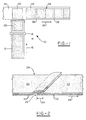
- a ply manufacturing sequence preferably for use in producing tire body plies, is designated generally by the numeral 10.
- the line 10 includes an inlet conveyor 12 for moving a web 14 of elastomeric material having reinforcing cords of wire or the like longitudinally extended therein.
- the arrow 16 designates the direction of the movement of the web 14.
- an appropriate cutter 18 traverses the inlet conveyor 12 to make periodic cutting engagement with the web 14 to repeatedly cut sections 20 of fixed length therefrom.
- the length of the sections or mats 20 is equivalent to the width of the resulting body ply web being manufactured.
- the sections or mats 20 are transferred to a conveyor 22 which runs orthogonal to the inlet conveyor 12, in the direction of the arrow 24.
- the conveyors 12, 22 do not necessarily move on a continual basis, but in indexing fashion. This indexed movement allows a worker or operator standing along the side of the conveyor 22 to lap each of the sections 20 onto the preceding section 20 to effect and overlapping splice 26 in order to form the web 28 of body ply material.
- this web 28 of body ply material has lateral cords extending therethrough, the same being transverse with respect to the longitudinal direction of movement of the web 28 as indicated by the arrow 24.
- each of the splices 26 is formed by overlapping the loading edge of a subsequent section 20 onto the trailing edge of a prior section 20 in a manner well known and understood by those skilled in the art.
- each of the mats or sections 20 comprises a rubber base 30 having cords 32 of metallic, synthetic wire or the like extending laterally therethrough.
- the leading edge of the trailing mat is lapped over the trailing edge of the leading mat to effect the splice 26.
- the splice width designated by the numeral 34, should be not only of a fixed dimension, but of a constant dimension across the web to prevent any canting or skewing of the splice 26. While it has been found that workers can typically maintain splice consistency by experience and "feel," the need for a monitor for splice width control is apparent.
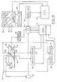
- Fig. 3 it can be seen that the web 28 is caused to move in the direction indicated by the arrow 24 in the manner discussed previously.
- An encoder 36 of suitable nature is brought into contacting engagement with the moving web 28 to produce an output signal comprising a series of pulses having a frequency which is directly proportioned to the speed at which mat 28 moves.
- the implementation of encoder 36 or tachometers or other suitable means for producing such signals is well known and understood by those skilled in the art.
- the output signal from the encoder 36 is passed to a frequency multiplier 38, the purpose of which is to increase the frequency of the output signal from the encoder 36 by some fixed multiple.
- the frequency multiplier 38 serves to increase the resolution of the encoder.
- each output pulse from the frequency multiplier 38 would represent a smaller lineal portion of the web 28 as a function of the inverse of the multiplication factor.
- the output of the frequency multiplier 38 is passed to an input/output board (I/O) 40 for transfer to the data signal processor 42.
- the processor 42 receives signals directly proportional to the instantaneous speed of movement of the web 28 and, accordingly, each pulse represents a finite increment of length of the web 28.
- a trigger mechanism 44 which continually monitors the movement of the web.
- the trigger mechanism 44 comprises a wheel 46 which is free-wheeling upon the web 28. Extending from the wheel 46 is a vane or blade 48 which is in selective operative engagement with an appropriate switch 50.
- the switch 50 comprises a contact or limit switch which is mechanically actuated as by contact with the vane or blade 48.
- the switch 50 is an optical switch having a light source and a light sensor with the vane positioned for movement therebetween. Accordingly, movement of the vane 48 between the source and sensor blocks the transmission of light and effects an appropriate output of the switch 50.
- the switch 50 could, indeed, comprise a linear variable differential transformer (LVDT), actuated by the vane or blade 48, the output signal of which is a function of the positioning of the vane 48.
- LVDT linear variable differential transformer
- the wheel 46 will ultimately come in contact with a "bump" traversing the web 28 and defined by the splice 26.
- the wheel 46 will cause the associated vane or blade 48 to make actuating contacting engagement with the switch 50, sending an appropriate signal through a signal processor 52 which, after appropriately scaling the signal, passes the same to the signal processor 42 through the I/O board 40.
- top sensor 54 and a vertically aligned bottom sensor 56 are also maintained in juxtaposition to the moving web 24.
- the sensors 54, 56 are laser sensors, impinging beams upon respective top and bottom surfaces of the web 28 and receiving reflected signals back therefrom. Accordingly, the sensors 54, 56 monitor the surface contours of the web 28 along respective lines defined by the travel of the web.
- the output from the sensors 54, 56 are respectively passed to top and bottom preamplifiers 58, 60 which appropriately buffer and scale such signals through signal processor 42.
- Signal processor 42 passes the analog data through the I/O board 40 to a sample/hold analog-to-digital convertor circuit 62.
- a sample/hold circuit receives signals and updates the receipt of such signals to maintain therein a signal corresponding to the peak amplitude of the signals received. Accordingly, a sample/hold circuit 62 will typically contain therein a signal from the top sensor 54 indicative of the leading edge of the splice 26, while also retaining a signal from the bottom sensor 56 corresponding to the trailing edge of the splice 26.
- the output of the sample/hold circuit 62 is passed to a central processing unit 64 which also receives the pulses from the encoder 36 as increased in resolution by the multiplier 38. With each of the pulses from the encoder 36 being indicative of a fixed incremental length of web 28, the central processing unit 64 may simply count the number of pulses between the peak signal sensed by the sensor 54 and the peak signal sensed by the sensor 56 to determine the actual spacing between the leading and trailing edges of the splice 26 and, accordingly, determine the splice width at that point.
- sensors 54, 56 could be employed in accordance with the teachings of the invention.
- the sensors would typically be vertically aligned near the center of the web 28 to determine the width of the splice 26 at the center thereof.
- another set of sensors top sensor 66 and bottom sensor 68, may be employed at the far edge of the web 28, being identical in nature to the sensors 54, 56 which would then be aligned at the near edge of the web.
- the sensors 54, 56, 66, 68 are coplanar, simultaneously measuring points on top and bottom surfaces of the web 28 which would also be coplanar.
- the top sensor 66 passes its output signal to a preamplifier 70, while the bottom sensor 68 passes its output signal to a preamplifier 72, the same being respectively similar to the preamplifiers 58, 60. Suffice it to say that the outputs from the preamplifiers 70, 72 are appropriately buffered and scaled before being passed to the data signal processor 42 for treatment as discussed previously.
- the absolute width of the splice 26 at each of opposite lateral ends thereof can be determined. With this information, it can also be determined whether the splice 26 is canted or skewed. Indeed, knowing the geometrical data of the splice 26 at the ends thereof, the geometry of the splice across its entire length can be fairly projected.
- a monitor 76 having a CRT screen 78 is provided. Pairs of lamp arrays or other visual indicia 80 are also provided so that the worker or operator effecting the splices 26 may observe the accuracy of such splices by reference to the monitor 76 which is maintained in his immediate vicinity. It is contemplated that two arrays 80 of five lamps each are provided with the monitor 76, one associated with each of the pairs of sensors 54, 56 and 66, 68. If the splice 26 is of acceptable width at both of the monitored ends thereof, the center light of each array 80 is illuminated to show the same to be acceptable.
- the appropriate lamp on either side of the center lamp of the lamps 80 may be illuminated. If the splice 26 deviates from the desired width by an amount exceeding a second level, the appropriate lamp at either end of the array 80 will be illuminated to indicate this condition. Accordingly, it will be appreciated that the arrays of lamps 80 represent the splice 26, with illumination of the center lamp indicating that both ends of the splice 26 are acceptable, and with illumination of lamps on either side of the center lamp indicating that the splice is above or below a desired width or dimension on the associated side of the web. The operator can then take corrective action on his next splice to be sure that he does not repeat the error.
- the CRT 78 of the monitor 76 may actually show a rendering of the geometry of the splice 26 so that the operator can appreciate the deviation or error and make appropriate corrective action.
- the monitor 76 may show traces for each of the pairs of sensors 54, 56 and 66, 68, or may actually display a single trace of the entire length of the splice as determined by the processor 64.
- the trigger mechanism 44 is used to signal the processor 42 and central processing unit 64 of the proximity of a splice 26 so that data can be taken from the sensors 54, 56, 66, 68 only in that time frame in which the splice 26 would be present within the field of view of the sensors.
- the switch 50 presents an output signal it will be known that the splice 26 will arrive at the plane of the array of sensors after a fixed number of pulses from the encoder 36 have been generated.
- the sample/hold circuit 62 can be caused to accept data only during this time frame such that the system is not overwhelmed with data, and so that anomalies or other possible defects within the web 28 are not confused with splices.
- the sample/hold circuit 62 is reset to receive new data from the next subsequent splice.
- the processor 64 may readily employ the lap splice data obtained from the sensors 54, 56, 66, 68 in a feedback loop to control the conveyors 12, 22, and to modify the lap splices in an automated system. Additionally, the data received by the processor 64 may be stored as a log or history of the spliced web of material, if desired.
Landscapes
- Physics & Mathematics (AREA)
- General Physics & Mathematics (AREA)
- Tyre Moulding (AREA)
- Length Measuring Devices With Unspecified Measuring Means (AREA)
- Folding Of Thin Sheet-Like Materials, Special Discharging Devices, And Others (AREA)
Claims (20)
- Vorrichtung zum Messen der Überlappungsbreite einer Reifenunterbaulage unter Überwachung einer sich bewegenden Bahn (28) des Unterbaulagenmaterials, die aus einer Vielzahl von Abschnitten (20) gebildet wird, wobei jeder Abschnitt an einem angrenzenden Abschnitt durch Überlappen einer Kante des einen Abschnittes mit der Kante des anderen Abschnittes der Bahn (28) an einer Spleißstelle fixiert wird, umfassend:
erste Mittel (36,38) zum Überwachen der Bewegungsgeschwindigkeit der Bahn (28) und Erzeugung eines ersten dazu entsprechenden Ausgangssignales,
zweite Mittel (54,66) zum Erfassen einer ersten Kante der Spleißstelle (26) und anschliessendes Erzeugen eines zweiten dazu entsprechenden Ausgangssignales,
dritte Mittel (56,88) zum Erfassen einer zweiten Kante der Spleißstelle (26) und anschließendes Erzeugen eines dritten Ausgangssignales, und
vierte Mittel (42,62,64), die die ersten, zweiten und dritten Mittel verbinden und die entsprechenden Ausgangssignale aufnehmen, unter Ermittlung der Breite der Spleißung (26) als eine Funktion des relativen Abstands des zweiten Ausgangssignals vom dritten. - Vorrichtung zum Messen der Überlappungsbreite einer Reifenunterbaulage nach Anspruch 1, bei der die zweiten (54,66) und die dritten (56,68) Mittel auf gegenüberliegenden Seiten der Bahn bzw. Lage (28) positioniert sind.
- Vorrichtung zum Messen der Überlappungsbreite einer Reifenunterbaulage nach Anspruch 2, bei der die zweiten Mittel (54,66) eine vordere Kante des einen Abschnitts ermitteln und die dritten Mittel (56,68) die hintere Kante des anderen Abschnitts ermitteln.
- Vorrichtung zum Messen der Überlappungsbreite einer Reifenunterbaulage nach Anspruch 3, bei der die ersten Mittel eine Codiervorrichtung (36) umfassen, die durch die sich bewegende Bahn (28) angetrieben wird, und wobei das erste Ausgangssignal eine Impulsserie einer Frequenz umfaßt, die der Bewegungsgeschwindigkeit der Bahn entspricht.
- Vorrichtung zum Messen der Überlappungsbreite einer Reifenunterbaulage nach Anspruch 4, bei der die vierten Mittel eine Tastspeicherschaltung (62) umfassen, die mit den zweiten (54,66) und den dritten (56,68) Mitteln verbunden sind und die zweiten und dritten Ausgangssignale aufnimmt.
- Vorrichtung zum Messen der Überlappungsbreite einer Reifenunterbaulage nach Anspruch 5, ferner umfassend Schaltungsmittel (50), die in betriebsmäßigen Kontakteingriff mit der Bahn (28) stehen und mit den vierten Mitteln (42,62,64) verbunden sind, wobei die Schaltungsmittel ein viertes Ausgangssignal zu den vierten Mitteln liefern, nachdem sie eine Spleißung (26) in der Bewegungsbahn erfassen und berühren.
- Vorrichtung zum Messen der Überlappungsbreite einer Reifenunterbaulage nach Anspruch 6, bei der die vierten Mittel die Tastspeicherschaltung (62) für eine festgelegte Zeitspanne nach Empfang des vierten Signals betätigen, wobei die festgelegte Zeitspanne eine Zeit umfaßt, zu der die Spleißung (26) zu den zweiten (54,66) und den dritten (56,68) Mitteln ausgerichtet ist und die zweiten und dritten Signale erzeugt werden.
- Vorrichtung zum Messen der Überlappungsbreite einer Reifenunterbaulage nach Anspruch 3, bei der die zweiten Mittel einen ersten Sensor (54) umfassen, der oberhalb der Bahn angeordnet ist, und wobei das dritte Mittel einen zweiten Sensor (56) umfaßt, der unterhalb der Bahn angeordnet ist.
- Vorrichtung zum Messen der Überlappungsbreite einer Reifenunterbaulage nach Anspruch 8, wobei das zweite Mittel ferner einen dritten Sensor (66) umfaßt, der über der Bahn positioniert ist, sowie einen vierten Sensor (68), der unter der Bahn positioniert ist, und wobei der erste und der zweite Sensor an einer ersten Seitenkante der Bahn positioniert sind, während der dritte und der vierte Sensor an einer zweiten Seitenkante der Bahn positioniert sind.
- Vorrichtung zum Messen der Überlappungsbreite einer Reifenunterbaulage nach Anspruch 9, bei der der erste, der zweite, der dritte und der vierte Sensor (54,56,66,68) koplanar zueinander sind.
- Vorrichtung zum Messen der Überlappungsbreite einer Reifenunterbaulage nach Anspruch 9, ferner umfaßend einen Monitor (76), der mit den vierten Mitteln verbunden ist und visuelle Indizien der Spleißbreite (26) erzeugt.
- Vorrichtung zum Messen der Überlappungsbreite einer Reifenunterbaulage nach Anspruch 11, bei der der Monitor bzw. die Vorrichtung Indizien der Spleißungsbreite an der ersten und zweiten Seitenkante aufzeigt.
- Vorrichtung zum Messen der Überlappungsbreite einer Reifenunterbaulage nach Anspruch 12, bei der die Vorrichtung bzw. der Monitor (76) Indizien der geometrischen Veränderungen in der Spleißung an der ersten und zweiten Seitenkante aufzeigt.
- Vorrichtung zum Messen der Überlappungsbreite einer Reifenunterbaulage unter Überwachung von Spleißungen in einer Bewegungsbahn (28) von Materialien, umfassend: eine Codiervorrichtung (36) in Kommunikation mit der Bahn (28) und Erzeugung eines ersten Signals, das den Weg der Bahn zeigt,
erste und zweite Sensoren (54,56), die entsprechend ober- und unterhalb der Bahn angeordnet sind und erste und zweite lineare Wege auf der oberen bzw. unteren Fläche der Bahn erfaßt und zweite bzw. dritte Signale erzeugt, sowie Verarbeitungsmittel (42,62,64), die das erste, zweite und dritte Signal aufnimmen und daraus die Spleißungsbreite feststellen. - Vorrichtung zum Messen der Überlappungsbreite nach Anspruch 14, ferner umfassend einen Monitor (76), der Indizien eines Vergleiches der Spleißungsbreite mit vorgegebenen Abmessungen vorsieht.
- Vorrichtung nach Anspruch 15, ferner umfassend dritte und vierte Sensoren (66,68), die oberhalb bzw. unterhalb der Bahn (28) angeordnet sind und dritte und vierte lineare Wege auf der oberen bzw. unteren Fläche der Bahn erfassen, wobei der erste und zweite Sensor (54,56) an einer ersten Seitenkante der Bahn positioniert sind, während die dritten und vierten Sensoren (66,68) an einer zweiten Seitenkante der Bahn positioniert sind.
- Vorrichtung zum Messen der Überlappungsbreite einer Reifenunterbaulage nach Anspruch 16, bei der der Monitor (76) ein Indiz (80) des Vergleiches der Spleißbreite mit vorgegebenen Abmessungen an zwei Stellen der Spleißung angibt, und ferner ein Indiz (78) der Spleißbreitengeometrie liefert.
- Vorrichtung zum Messen der Überlappungsbreite einer Reifenunterbaulage nach Anspruch 16, ferner umfassend einen fünften Sensor (46,48,50), der mit den Verarbeitungsmitteln verbunden ist und eine Fläche der Bahn erfaßt, und wobei der fünfte Sensor ein Ausgangssignal zu den Verarbeitungsmitteln (42,62,64) liefert, nachdem er die Spleißung (26) in der sich bewegenden Bahn (28) ermittelt hat, und wobei das Verarbeitungsmittel daraufhin Daten vom ersten, zweiten, dritten und vierten Sensor (54,56,66,68) für eine Zeitspanne empfängt, in der die Daten die Spleißung umfassen.
- Vorrichtung zum Messen der Überlappungsbreite einer Reifenunterbaulage nach Anspruch 18, wobei der erste, zweite, dritte und vierte Sensor (54,56,66,68) Lasersensoren umfassen.
- Vorrichtung zum Messen der Überlappungsbreite einer Reifenunterbaulage nach Anspruch 19, wobei der fünfte Sensor einen Schalter (50) umfaßt.
Applications Claiming Priority (2)
| Application Number | Priority Date | Filing Date | Title |
|---|---|---|---|
| US07/772,991 US5271284A (en) | 1991-10-08 | 1991-10-08 | Lap splice width monitor |
| US772991 | 1991-10-08 |
Publications (2)
| Publication Number | Publication Date |
|---|---|
| EP0536704A1 EP0536704A1 (de) | 1993-04-14 |
| EP0536704B1 true EP0536704B1 (de) | 1995-12-13 |
Family
ID=25096841
Family Applications (1)
| Application Number | Title | Priority Date | Filing Date |
|---|---|---|---|
| EP92117061A Expired - Lifetime EP0536704B1 (de) | 1991-10-08 | 1992-10-06 | Vorrichtung zum Messen der Breite der Überlappung einer Klebestelle |
Country Status (6)
| Country | Link |
|---|---|
| US (1) | US5271284A (de) |
| EP (1) | EP0536704B1 (de) |
| JP (1) | JP3199872B2 (de) |
| KR (1) | KR100242094B1 (de) |
| DE (1) | DE69206747T2 (de) |
| ES (1) | ES2080409T3 (de) |
Cited By (3)
| Publication number | Priority date | Publication date | Assignee | Title |
|---|---|---|---|---|
| DE19632696C1 (de) * | 1996-08-14 | 1998-04-23 | Thyssen Stahl Ag | Verfahren und Vorrichtung zum Messen der Überlappungsbreite eines Überlappungsstoßes von zwei flach aufeinanderliegenden Werkstücken |
| DE102004015110A1 (de) * | 2004-03-27 | 2005-10-13 | Texmag Gmbh Vertriebsgesellschaft | Verfahren und Vorrichtung zum Erfassen des Überlapps von Bahnstücken |
| RU2638128C1 (ru) * | 2013-11-06 | 2017-12-11 | Фудзи Сейко Ко., Лтд. | Способ проверки участка соединения наполнителя |
Families Citing this family (9)
| Publication number | Priority date | Publication date | Assignee | Title |
|---|---|---|---|---|
| US5665907A (en) * | 1994-09-06 | 1997-09-09 | The University Of Chicago | Ultrasonic imaging system for in-process fabric defect detection |
| US5845232A (en) * | 1996-05-10 | 1998-12-01 | Measurement Systems, Incorporated | Apparatus and method for detecting splice overlaps or splice gaps in a tire |
| US5895535A (en) * | 1997-09-24 | 1999-04-20 | Eastman Kodak Company | Apparatus and method for measuring web alignment at a splice |
| US5953953A (en) * | 1997-10-16 | 1999-09-21 | Eastman Kodak Company | Apparatus and method for detecting a splice in a running length of web |
| US6836331B2 (en) * | 1999-11-20 | 2004-12-28 | Bhs Corrugated Maschinen-Und Anlagenbau Gmbh | Apparatus for detection of format accuracy of a web of corrugated board |
| US7014083B2 (en) * | 2002-10-17 | 2006-03-21 | Kimberly-Clark Worldwide, Inc. | System and method for controlling the width of web material |
| MX338101B (es) * | 2009-07-15 | 2016-04-01 | Bridgestone Corp | Dispositivo y método para fabricar un elemento constituyente de un neumático. |
| US20110146887A1 (en) * | 2009-12-21 | 2011-06-23 | Daniel Ray Downing | Tire ply and method of manufacture |
| CN115682960B (zh) * | 2022-12-29 | 2023-03-31 | 钛玛科(北京)工业科技有限公司 | 一种测量帘布接头宽度的系统和方法 |
Family Cites Families (22)
| Publication number | Priority date | Publication date | Assignee | Title |
|---|---|---|---|---|
| US2988917A (en) * | 1957-01-22 | 1961-06-20 | Western Electric Co | Open seam detector for metal sheathed cables |
| US2989690A (en) * | 1959-04-29 | 1961-06-20 | Gen Electric | Elongation, length, and velocity gage |
| NL293013A (de) * | 1962-05-22 | |||
| US3283163A (en) * | 1963-11-06 | 1966-11-01 | Ibm | Photosensitive overlapped document detector |
| US3428818A (en) * | 1965-03-04 | 1969-02-18 | Chauncey L Grebe | Method and apparatus for determining camber in a moving strip |
| US3843434A (en) * | 1972-06-12 | 1974-10-22 | Industrial Nucleonics Corp | Process control |
| GB1574263A (en) * | 1977-07-27 | 1980-09-03 | Measurex Corp | Measurement of tread length |
| US4238261A (en) * | 1978-10-02 | 1980-12-09 | The Black Clawson Company | Method for forming a zero tail length splice in a moving web |
| JPS5692404A (en) * | 1979-12-25 | 1981-07-27 | Unitika Ltd | Automatic measuring method for length of cloth width |
| JPS56161507U (de) * | 1980-05-01 | 1981-12-01 | ||
| GB2083214B (en) * | 1980-09-03 | 1984-01-11 | Baker Perkins Holdings Ltd | Dimension monitoring apparatus |
| US4482972A (en) * | 1981-06-25 | 1984-11-13 | Lewis Clarence A | Distance sensing apparatus and method |
| DE3220629C2 (de) * | 1982-06-01 | 1984-12-13 | Bernhard Dipl.-Ing.(TH) 7800 Freiburg Ehret | Steuervorrichtung zur Verleimung von Endlossätzen |
| DE3312111A1 (de) * | 1983-04-02 | 1984-10-04 | Waco Jonsereds AB, Halmstad | Vorrichtung zum registrieren solcher stellen an einem brett, wo spaeter ein schnitt ausgefuehrt werden soll |
| US4513613A (en) * | 1983-06-07 | 1985-04-30 | International Business Machines Corporation | Particle detection system |
| US4650991A (en) * | 1983-07-01 | 1987-03-17 | De La Rue Systems Limited | Method and apparatus for sensing sheets |
| US4550377A (en) * | 1983-10-24 | 1985-10-29 | Molins Machine Company, Inc. | Proximity flute detection |
| US4552602A (en) * | 1984-06-04 | 1985-11-12 | The B. F. Goodrich Company | High--speed splicing system for preparing ply stock |
| US4888717A (en) * | 1984-11-02 | 1989-12-19 | Adolph Coors Company | Web lateral position control apparatus and method |
| DE3708186A1 (de) * | 1987-03-13 | 1988-09-22 | Hergeth Hubert | Vorrichtung und verfahren zum hochgenauen messen von fasermatten |
| JPS6470344A (en) * | 1987-09-03 | 1989-03-15 | Bridgestone Corp | Method and apparatus for bonding strip like member |
| US4931113A (en) * | 1989-03-09 | 1990-06-05 | Tecton Laminates Corp. | Veneer edge joinder method and apparatus |
-
1991
- 1991-10-08 US US07/772,991 patent/US5271284A/en not_active Expired - Fee Related
-
1992
- 1992-10-06 EP EP92117061A patent/EP0536704B1/de not_active Expired - Lifetime
- 1992-10-06 ES ES92117061T patent/ES2080409T3/es not_active Expired - Lifetime
- 1992-10-06 DE DE69206747T patent/DE69206747T2/de not_active Expired - Fee Related
- 1992-10-08 JP JP29403192A patent/JP3199872B2/ja not_active Expired - Fee Related
- 1992-10-08 KR KR1019920018494A patent/KR100242094B1/ko not_active Expired - Fee Related
Cited By (3)
| Publication number | Priority date | Publication date | Assignee | Title |
|---|---|---|---|---|
| DE19632696C1 (de) * | 1996-08-14 | 1998-04-23 | Thyssen Stahl Ag | Verfahren und Vorrichtung zum Messen der Überlappungsbreite eines Überlappungsstoßes von zwei flach aufeinanderliegenden Werkstücken |
| DE102004015110A1 (de) * | 2004-03-27 | 2005-10-13 | Texmag Gmbh Vertriebsgesellschaft | Verfahren und Vorrichtung zum Erfassen des Überlapps von Bahnstücken |
| RU2638128C1 (ru) * | 2013-11-06 | 2017-12-11 | Фудзи Сейко Ко., Лтд. | Способ проверки участка соединения наполнителя |
Also Published As
| Publication number | Publication date |
|---|---|
| KR930007622A (ko) | 1993-05-20 |
| US5271284A (en) | 1993-12-21 |
| KR100242094B1 (ko) | 2000-03-02 |
| DE69206747T2 (de) | 1996-05-23 |
| DE69206747D1 (de) | 1996-01-25 |
| ES2080409T3 (es) | 1996-02-01 |
| JP3199872B2 (ja) | 2001-08-20 |
| JPH05196455A (ja) | 1993-08-06 |
| EP0536704A1 (de) | 1993-04-14 |
Similar Documents
| Publication | Publication Date | Title |
|---|---|---|
| EP0536704B1 (de) | Vorrichtung zum Messen der Breite der Überlappung einer Klebestelle | |
| US4965733A (en) | Cutting apparatus for sheet-like materials | |
| US4548105A (en) | Method and arrangement for observing a position | |
| US4285752A (en) | Automatic tape lay-up system | |
| US4557019A (en) | Automatic portion-cutting method and machine | |
| KR101140074B1 (ko) | 컷팅 장치 | |
| JPH02500971A (ja) | 可変繰り返し長さ部分を持つウェブ用の調整制御システム | |
| JPH03133819A (ja) | コンベアベルトまたはコンベアスケールの走行状態を監視するための方法および装置 | |
| CA1046604A (en) | Automatic flat width control | |
| US4330941A (en) | Measuring linear displacement of an object | |
| KR910016591A (ko) | 띠형상부재 절단, 권희방법 및 장치 | |
| NZ532456A (en) | Method and apparatus for centering a log | |
| JP2005077096A (ja) | レールふく進測定装置及び測定方法並びに基準となるターゲットの設置方法 | |
| CN1946544B (zh) | 切割工具 | |
| JPS6357737B2 (de) | ||
| JP3020991B2 (ja) | 帯状部材巻付方法および装置 | |
| JP2007315901A (ja) | 非接触式のジョイント量測定装置 | |
| JPH063137A (ja) | ベルト内の心体埋設位置の計測方法 | |
| JP2001201335A (ja) | シート材の幅方向両端位置測定方法及びその装置 | |
| JPS6245136B2 (de) | ||
| JPH0257646B2 (de) | ||
| JPH07195571A (ja) | コーティングシートの端部切断装置 | |
| JPH02176505A (ja) | 検出装置及び検出方法 | |
| JP2004082392A (ja) | 補強コード埋設帯状ゴムシート部材の端部切断方法と装置及び補強コード位置検出方法と装置 | |
| JPH08168919A (ja) | 条鋼圧延設備の製品長さ切断装置 |
Legal Events
| Date | Code | Title | Description |
|---|---|---|---|
| PUAI | Public reference made under article 153(3) epc to a published international application that has entered the european phase |
Free format text: ORIGINAL CODE: 0009012 |
|
| AK | Designated contracting states |
Kind code of ref document: A1 Designated state(s): DE ES FR GB IT |
|
| 17P | Request for examination filed |
Effective date: 19930802 |
|
| 17Q | First examination report despatched |
Effective date: 19941114 |
|
| GRAA | (expected) grant |
Free format text: ORIGINAL CODE: 0009210 |
|
| AK | Designated contracting states |
Kind code of ref document: B1 Designated state(s): DE ES FR GB IT |
|
| REF | Corresponds to: |
Ref document number: 69206747 Country of ref document: DE Date of ref document: 19960125 |
|
| REG | Reference to a national code |
Ref country code: ES Ref legal event code: FG2A Ref document number: 2080409 Country of ref document: ES Kind code of ref document: T3 |
|
| ITF | It: translation for a ep patent filed | ||
| ET | Fr: translation filed | ||
| PG25 | Lapsed in a contracting state [announced via postgrant information from national office to epo] |
Ref country code: GB Effective date: 19961006 |
|
| PG25 | Lapsed in a contracting state [announced via postgrant information from national office to epo] |
Ref country code: ES Free format text: LAPSE BECAUSE OF NON-PAYMENT OF DUE FEES Effective date: 19961007 |
|
| PLBE | No opposition filed within time limit |
Free format text: ORIGINAL CODE: 0009261 |
|
| 26N | No opposition filed | ||
| GBPC | Gb: european patent ceased through non-payment of renewal fee |
Effective date: 19961006 |
|
| PGFP | Annual fee paid to national office [announced via postgrant information from national office to epo] |
Ref country code: FR Payment date: 20011005 Year of fee payment: 10 |
|
| PGFP | Annual fee paid to national office [announced via postgrant information from national office to epo] |
Ref country code: DE Payment date: 20011030 Year of fee payment: 10 |
|
| PG25 | Lapsed in a contracting state [announced via postgrant information from national office to epo] |
Ref country code: DE Free format text: LAPSE BECAUSE OF NON-PAYMENT OF DUE FEES Effective date: 20030501 |
|
| PG25 | Lapsed in a contracting state [announced via postgrant information from national office to epo] |
Ref country code: FR Free format text: LAPSE BECAUSE OF NON-PAYMENT OF DUE FEES Effective date: 20030630 |
|
| REG | Reference to a national code |
Ref country code: FR Ref legal event code: ST |
|
| REG | Reference to a national code |
Ref country code: ES Ref legal event code: FD2A Effective date: 19971112 |
|
| PG25 | Lapsed in a contracting state [announced via postgrant information from national office to epo] |
Ref country code: IT Free format text: LAPSE BECAUSE OF NON-PAYMENT OF DUE FEES;WARNING: LAPSES OF ITALIAN PATENTS WITH EFFECTIVE DATE BEFORE 2007 MAY HAVE OCCURRED AT ANY TIME BEFORE 2007. THE CORRECT EFFECTIVE DATE MAY BE DIFFERENT FROM THE ONE RECORDED. Effective date: 20051006 |