EP0536849B1 - Kontaktvorrichtung für ein Kabel mit einem oder mehreren inneren Leitern - Google Patents
Kontaktvorrichtung für ein Kabel mit einem oder mehreren inneren Leitern Download PDFInfo
- Publication number
- EP0536849B1 EP0536849B1 EP92203114A EP92203114A EP0536849B1 EP 0536849 B1 EP0536849 B1 EP 0536849B1 EP 92203114 A EP92203114 A EP 92203114A EP 92203114 A EP92203114 A EP 92203114A EP 0536849 B1 EP0536849 B1 EP 0536849B1
- Authority
- EP
- European Patent Office
- Prior art keywords
- contact device
- connection terminal
- cable
- shield
- inner conductor
- Prior art date
- Legal status (The legal status is an assumption and is not a legal conclusion. Google has not performed a legal analysis and makes no representation as to the accuracy of the status listed.)
- Expired - Lifetime
Links
Images


Classifications
-
- H—ELECTRICITY
- H01—ELECTRIC ELEMENTS
- H01R—ELECTRICALLY-CONDUCTIVE CONNECTIONS; STRUCTURAL ASSOCIATIONS OF A PLURALITY OF MUTUALLY-INSULATED ELECTRICAL CONNECTING ELEMENTS; COUPLING DEVICES; CURRENT COLLECTORS
- H01R9/00—Structural associations of a plurality of mutually-insulated electrical connecting elements, e.g. terminal strips or terminal blocks; Terminals or binding posts mounted upon a base or in a case; Bases therefor
- H01R9/03—Connectors arranged to contact a plurality of the conductors of a multiconductor cable, e.g. tapping connections
- H01R9/05—Connectors arranged to contact a plurality of the conductors of a multiconductor cable, e.g. tapping connections for coaxial cables
- H01R9/0518—Connection to outer conductor by crimping or by crimping ferrule
-
- H—ELECTRICITY
- H01—ELECTRIC ELEMENTS
- H01R—ELECTRICALLY-CONDUCTIVE CONNECTIONS; STRUCTURAL ASSOCIATIONS OF A PLURALITY OF MUTUALLY-INSULATED ELECTRICAL CONNECTING ELEMENTS; COUPLING DEVICES; CURRENT COLLECTORS
- H01R13/00—Details of coupling devices of the kinds covered by groups H01R12/70 or H01R24/00 - H01R33/00
- H01R13/648—Protective earth or shield arrangements on coupling devices, e.g. anti-static shielding
- H01R13/658—High frequency shielding arrangements, e.g. against EMI [Electro-Magnetic Interference] or EMP [Electro-Magnetic Pulse]
- H01R13/6591—Specific features or arrangements of connection of shield to conductive members
- H01R13/65912—Specific features or arrangements of connection of shield to conductive members for shielded multiconductor cable
-
- H—ELECTRICITY
- H02—GENERATION; CONVERSION OR DISTRIBUTION OF ELECTRIC POWER
- H02G—INSTALLATION OF ELECTRIC CABLES OR LINES, OR OF COMBINED OPTICAL AND ELECTRIC CABLES OR LINES
- H02G1/00—Methods or apparatus specially adapted for installing, maintaining, repairing or dismantling electric cables or lines
- H02G1/12—Methods or apparatus specially adapted for installing, maintaining, repairing or dismantling electric cables or lines for removing insulation or armouring from cables, e.g. from the end thereof
- H02G1/1273—Methods or apparatus specially adapted for installing, maintaining, repairing or dismantling electric cables or lines for removing insulation or armouring from cables, e.g. from the end thereof by pushing backwards insulation
-
- H—ELECTRICITY
- H01—ELECTRIC ELEMENTS
- H01R—ELECTRICALLY-CONDUCTIVE CONNECTIONS; STRUCTURAL ASSOCIATIONS OF A PLURALITY OF MUTUALLY-INSULATED ELECTRICAL CONNECTING ELEMENTS; COUPLING DEVICES; CURRENT COLLECTORS
- H01R13/00—Details of coupling devices of the kinds covered by groups H01R12/70 or H01R24/00 - H01R33/00
- H01R13/648—Protective earth or shield arrangements on coupling devices, e.g. anti-static shielding
- H01R13/658—High frequency shielding arrangements, e.g. against EMI [Electro-Magnetic Interference] or EMP [Electro-Magnetic Pulse]
- H01R13/6591—Specific features or arrangements of connection of shield to conductive members
- H01R13/6592—Specific features or arrangements of connection of shield to conductive members the conductive member being a shielded cable
Definitions
- the invention relates to a contact device for a cable comprising one or more inner conductors with inner insulating sheath and a common shield with outer insulating sheath, said contact device comprising a connection terminal for the shield and a connection terminal for each inner conductor.
- US 4,719,697 discloses a method and device wherein the inner insulating sheath of an inner conductor is axially compressed by means of a special tool whereby the inner conductor is exposed. Subsequently the cable with exposed inner conductor is inserted into a usual contact device and attached in the same in the usual manner. Therefore this known solution requires a special preparation step of the cable which requires to provide a special tool device.
- the invention aims to provide a contact device of the above-mentioned type wherein connecting the cable with the contact device can be substantially simplified.
- the contact device of the above-mentioned type is characterized to this end by the characterizing features of claim 1.
- each stop element is formed by an end edge of each corresponding connection terminal for an inner conductor and/or of a dielectric insert of the contact device.
- each guiding element is formed by an annular channel having an inner diameter corresponding with the outer diameter of the inner insulating sheath of the inner conductor.
- each guiding element consists of electrically conductive material and is connected with the connection terminal for the shield.
- connection terminal for the shield is formed by a ring adapted to align the cable with its inner conductor(s) with the guiding element(s).
- connection terminal for the shield provides a type of prepositioning of the cable whereby each inner conductor can be easily inserted into the corresponding guiding element.
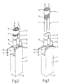
- Fig. 1 perspectively shows an embodiment of a contact device according to the invention, wherein an end part of a twinaxial cable is shown before the same is inserted into the contact device.
- Fig. 2 perspectively shows the contact device of fig. 1, wherein the cable end part is completely inserted into the contact device.
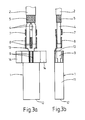
- Fig. 3a, 3b - 5a, 5b show partly in cross section a top view and a side view, respectively, of successive steps during the insertion of the cable and into the contact device of fig. 1.
- a contact device 1 for a twinaxial cable 2 an end part of which is shown in fig. 1. It is noted that the contact device can of course also be adapted for a coaxial cable.
- the twinaxial cable 1 is provided with two inner conductors 3 with an inner insulating sheath 4 and a common shield 5 consisting of braided metal wire.
- the shield 5 is enclosed by an outer insulating sheath 6.
- the end part of the cable 2 is stripped of a part of the outer insulating sheath 6 and a part of the shield 5, so that both inner conductors 3 with insulating sheath 4 extend out of the shield 5.
- the contact 1 comprises a connection terminal 7 for the shield 5, said connection element 7 consisting in this case of a flat ring.
- the connection terminal 7 is followed by a guiding element 8 for each inner conductor 3 with insulating sheath 4, which guiding element in the embodiment shown is made of the same material as the connection terminal 7 and is made as an annular channel fittingly enclosing the inner conductor 3 with insulating sheath 4.
- connection element 7 is located in such a manner with respect to the guiding elements 8 that during insertion of the inner conductors 3 with insulating sheath 4 in the connection terminal 7, said inner conductors 3 are aligned with the guiding element 8. Thereby pushing the inner conductors 3 with insulating sheath 4 into the guiding elements 8 is facilitated.
- connection terminal 9 for each inner conductor 3, wherein the connection terminals 9 are separated from the shield 11 of the contact 1 by a dielectric insert 10 consisting of insulating material.
- the drawing shows that the connection terminal 7 and the guiding elements 8 are formed of an extension of this shield 11.
- the coupling part 12 which can be connected to a coupling socket or the like, is not further shown and does not form part of the present invention.
- each connection terminal 9 and/or the dielectric insert 10 forms a stop element, by which the inner insulating sheath 4 of the corresponding inner conductor 3 is stopped during insertion of the cable 2 into the contact device 1.
- Fig. 4a, 4b show the position in which the insulating sheath 4 of the inner conductors 3 just meets the end edge 13 of the connection terminal 9.
- the stop element can completely be formed by an end face of this insert.
- the insulating sheaths 4 of the inner conductors 3 are axially compressed by the stop elements 13, so that the ends of the inner conductors 3 will be exposed in front of the connection terminals 9 as shown in fig. 5a, 5b. Thereafter the ends of the inner conductors 3 can be simply connected with the connection terminals 9, for example by soldering.
- Fig. 2 shows the situation of fig. 5 in perspective view. After soldering the ends of the inner conductors 3, wings 14 of the shield 11 can be closed so that the shield 11 of the contact device 1 is completely closed again and thereby there is no interruption in the shielding anymore.
- connecting a contact device to the end of the cable 2 is very simple when using the described contact device 1.
- Removing the outer insulating sheath 6 and the shield 5 can be done in a usual manner, whereas it is not required to remove the inner insulating sheath 4 of the inner conductors 3.
- said inner conductors are automatically directed with their insulating sheath at the stop elements 13, whereby the insulating sheaths 4 are axially compressed and the inner conductors 3 are exposed.
- the guiding elements 8 further have the important advantage that they extend along a substantial part of the inner conductors 3, whereby also the part of these inner conductors 3 where the shield 5 is removed, still has a shielding.
Landscapes
- Coupling Device And Connection With Printed Circuit (AREA)
- Multi-Conductor Connections (AREA)
- Details Of Connecting Devices For Male And Female Coupling (AREA)
- Cable Accessories (AREA)
Claims (6)
- Kontaktvorrichtung (1) für ein Kabel (2), mit einem oder mehreren Innenleitern (3) mit Innenisolierungsmantel (4) sowie einer gemeinsamen Abschirmung (5) mit Außenisolierungsmantel (6), wobei die Kontaktvorrichtung einen Verbindungsanschluß (7) für die Abschirmung und einen Verbindungsanschluß (9) für jeden Innenleiter besitzt, gekennzeichnet durch ein Führungselement (8) und ein Anschlagelement (13) für jeden Innenleiter (3), wobei das Führungselement so beschaffen ist, daß es den Innenleiter mit seinem Innenisolierungsmantel an das zugehörige Anschlagelement (13) führt, um den Innenisolierungsmantel während des Einführens des Kabels in die Kontaktvorrichtung axial zusammenzudrücken, wobei in Kabeleinführungsrichtung betrachtet jeder Verbindungsanschluß (9) für einen Innenleiter (3) jenseits des zugehörigen Anschlagelements (13) angeordnet ist.
- Kontaktvorrichtung nach Anspruch 1, dadurch gekennzeichnet, daß jedes Anschlagelement durch eine Endkante (13) des jeweiligen Verbindungsanschlusses (9) für einen Innenleiter (3) und/oder durch einen Dielektrikumeinsatz (10) der Kontaktvorrichtung gebildet ist.
- Kontaktvorrichtung nach Anspruch 1 oder 2, dadurch gekennzeichnet, daß jedes Führungselement (8) durch einen ringförmigen Kanal gebildet ist.
- Kontaktvorrichtung nach Anspruch 3, dadurch gekennzeichnet, daß jedes Führungselement (8) aus elektrisch leitfähigem Material besteht und mit dem Verbindungsanschluß (7) für die Abschirmung (5) verbunden ist.
- Kontaktvorrichtung nach Anspruch 4, dadurch gekennzeichnet, daß sich jedes Führungselement (8) vom Verbindungsanschluß (7) für die Abschirmung (5) bis in die Nähe des zugehörigen Verbindungsanschlusses (9) für den Innenleiter (3) erstreckt.
- Kontaktvorrichtung nach irgendeinem der vorangehenden Ansprüche, dadurch gekennzeichnet, daß der Verbindungsanschluß (7) für die Abschirmung (5) durch einen Ring gebildet ist, der dazu dient, das Kabel (2) mit seinen Innenleitern (3) auf die Führungselemente (8) auszurichten.
Applications Claiming Priority (2)
| Application Number | Priority Date | Filing Date | Title |
|---|---|---|---|
| NL9101695 | 1991-10-09 | ||
| NL9101695A NL9101695A (nl) | 1991-10-09 | 1991-10-09 | Contact voor een kabel met een of meer binnengeleiders. |
Publications (2)
| Publication Number | Publication Date |
|---|---|
| EP0536849A1 EP0536849A1 (de) | 1993-04-14 |
| EP0536849B1 true EP0536849B1 (de) | 1997-01-02 |
Family
ID=19859793
Family Applications (1)
| Application Number | Title | Priority Date | Filing Date |
|---|---|---|---|
| EP92203114A Expired - Lifetime EP0536849B1 (de) | 1991-10-09 | 1992-10-08 | Kontaktvorrichtung für ein Kabel mit einem oder mehreren inneren Leitern |
Country Status (6)
| Country | Link |
|---|---|
| US (1) | US5495075A (de) |
| EP (1) | EP0536849B1 (de) |
| JP (1) | JP3386156B2 (de) |
| CA (1) | CA2079346C (de) |
| DE (1) | DE69216349T2 (de) |
| NL (1) | NL9101695A (de) |
Families Citing this family (20)
| Publication number | Priority date | Publication date | Assignee | Title |
|---|---|---|---|---|
| NL9302006A (nl) * | 1993-11-19 | 1995-06-16 | Framatome Connectors Belgium | Elektrisch contactelement. |
| US5725387A (en) * | 1996-03-01 | 1998-03-10 | Molex Incorporated | System for terminating the shield of a high speed cable |
| US5716236A (en) * | 1996-03-01 | 1998-02-10 | Molex Incorporated | System for terminating the shield of a high speed cable |
| US5961348A (en) * | 1996-03-01 | 1999-10-05 | Molex Incorporated | System for terminating the shield of a high speed cable |
| US5718607A (en) * | 1996-03-01 | 1998-02-17 | Molex Incorporated | System for terminating the shield of a high speed cable |
| US5829991A (en) * | 1996-03-01 | 1998-11-03 | Molex Incorporated | Grounding bridge for shielded interconnect cables and interconnect cables incorporating same |
| US6380485B1 (en) | 2000-08-08 | 2002-04-30 | International Business Machines Corporation | Enhanced wire termination for twinax wires |
| US6979202B2 (en) | 2001-01-12 | 2005-12-27 | Litton Systems, Inc. | High-speed electrical connector |
| US6843657B2 (en) * | 2001-01-12 | 2005-01-18 | Litton Systems Inc. | High speed, high density interconnect system for differential and single-ended transmission applications |
| US6910897B2 (en) | 2001-01-12 | 2005-06-28 | Litton Systems, Inc. | Interconnection system |
| DE10121762C1 (de) * | 2001-05-04 | 2003-02-20 | Siemens Ag | Steckverbinder zum Anschließen von Koaxialleitern |
| US20030176085A1 (en) * | 2002-02-25 | 2003-09-18 | Atl Technology, Lc. | Electrical connector assembly |
| TWM251379U (en) * | 2004-02-11 | 2004-11-21 | Comax Technology Inc | Grounding structure of electrical connector |
| WO2014160610A1 (en) | 2013-03-25 | 2014-10-02 | Fci Asia Pte. Ltd | Electrical cable assembly |
| TWI790785B (zh) | 2016-05-31 | 2023-01-21 | 美商安芬諾股份有限公司 | 電終端、纜線總成以及纜線端接方法 |
| US10944214B2 (en) | 2017-08-03 | 2021-03-09 | Amphenol Corporation | Cable connector for high speed interconnects |
| FR3074616B1 (fr) * | 2017-12-06 | 2019-11-01 | Raydiall | Piece d'adaptation d'impedance electrique pour connecteur monte sur cable a fils electriques isoles |
| US10930411B2 (en) * | 2018-10-11 | 2021-02-23 | International Business Machines Corporation | Hybrid cable assembly having shielded and unshielded portions |
| CN113728521B (zh) | 2019-02-22 | 2025-03-18 | 安费诺有限公司 | 高性能线缆连接器组件 |
| US12015220B2 (en) * | 2020-04-17 | 2024-06-18 | Baker Hughes Oilfield Operations, Llc | Power connector with gripping slips for electrical submersible pump |
Family Cites Families (11)
| Publication number | Priority date | Publication date | Assignee | Title |
|---|---|---|---|---|
| US3426317A (en) * | 1966-09-26 | 1969-02-04 | United Carr Inc | Electrical connector |
| US3577814A (en) * | 1969-08-28 | 1971-05-04 | Amp Inc | Apparatus for exposing core of an insulated wire |
| US3736548A (en) * | 1971-07-28 | 1973-05-29 | R Double | Electrical coupler |
| US4110550A (en) * | 1976-11-01 | 1978-08-29 | Amerace Corporation | Electrical connector with adaptor for paper-insulated, lead-jacketed electrical cables and method |
| US4397516A (en) * | 1981-05-26 | 1983-08-09 | The Bendix Corporation | Cable termination apparatus |
| GB8518141D0 (en) * | 1985-07-18 | 1985-08-21 | Raychem Ltd | Electrical crimp connection |
| US4719697A (en) * | 1985-08-05 | 1988-01-19 | Amp Incorporated | Method of preparing coaxial cable for termination |
| US4897046A (en) * | 1986-10-03 | 1990-01-30 | Minnesota Mining And Manufacturing Company | Shielded connector system for coaxial cables |
| DE3823617A1 (de) * | 1988-07-12 | 1990-01-18 | Gore W L & Co Gmbh | Metallische gehaeusehuelse fuer einen elektrischen steckverbinder und steckverbinder |
| GB9010559D0 (en) * | 1990-05-11 | 1990-07-04 | Bicc Plc | Termination of mineral insulated electric cable |
| JPH0452370U (de) * | 1990-09-10 | 1992-05-01 |
-
1991
- 1991-10-09 NL NL9101695A patent/NL9101695A/nl not_active Application Discontinuation
-
1992
- 1992-09-24 CA CA002079346A patent/CA2079346C/en not_active Expired - Fee Related
- 1992-10-08 DE DE69216349T patent/DE69216349T2/de not_active Expired - Fee Related
- 1992-10-08 EP EP92203114A patent/EP0536849B1/de not_active Expired - Lifetime
- 1992-10-09 JP JP27192292A patent/JP3386156B2/ja not_active Expired - Fee Related
-
1994
- 1994-02-18 US US08/198,646 patent/US5495075A/en not_active Expired - Lifetime
Also Published As
| Publication number | Publication date |
|---|---|
| EP0536849A1 (de) | 1993-04-14 |
| US5495075A (en) | 1996-02-27 |
| CA2079346C (en) | 2001-02-13 |
| JP3386156B2 (ja) | 2003-03-17 |
| NL9101695A (nl) | 1993-05-03 |
| JPH05205829A (ja) | 1993-08-13 |
| DE69216349T2 (de) | 1997-04-24 |
| CA2079346A1 (en) | 1993-04-10 |
| DE69216349D1 (de) | 1997-02-13 |
Similar Documents
| Publication | Publication Date | Title |
|---|---|---|
| US5495075A (en) | Coaxial connector | |
| EP0083464B1 (de) | Koaxialkabel mit Verbinder | |
| US5393244A (en) | Twist-on coaxial cable end connector with internal post | |
| US5725387A (en) | System for terminating the shield of a high speed cable | |
| US5716236A (en) | System for terminating the shield of a high speed cable | |
| EP0122700B1 (de) | Elektrischer Koaxialverbinder für Koaxialkabel mit mehrfachem Aussenleiter | |
| US4634208A (en) | Electrical plug connector and method of terminating a cable therewith | |
| US5823825A (en) | System for terminating the shield of a high speed cable | |
| US5711686A (en) | System for terminating the shield of a high speed cable | |
| US5718607A (en) | System for terminating the shield of a high speed cable | |
| EP0099633A1 (de) | Steckerdose eines Koaxialverbinders | |
| JPH0773937A (ja) | 同軸ケーブル用コネクタ | |
| US3297979A (en) | Crimpable coaxial connector | |
| EP0067727A1 (de) | Kabelanschlussvorrichtung | |
| US5768771A (en) | System for terminating the shield of a high speed cable | |
| US3538239A (en) | Grounding wire connector | |
| US4795356A (en) | Electrical tap connector assembly | |
| WO1988003713A1 (en) | Electrical connector devices and methods | |
| EP0125760A1 (de) | Stecker mit abschirmender Umhüllung | |
| EP0793298A2 (de) | Fertigungssystem für die Abschirmung eines Hochfrequenz-Kabels | |
| EP0525249B1 (de) | Elektrischer Verbinder und Verfahren um daran ein abgeschirmtes Kabel zu verbinden | |
| US7207839B1 (en) | Wrap-around ferrule for coaxial cable connector | |
| EP1642362B1 (de) | Koaxialkontakt | |
| US5984710A (en) | Shielded wire terminating structure | |
| US3909506A (en) | Coxial cable connector and method therefor |
Legal Events
| Date | Code | Title | Description |
|---|---|---|---|
| PUAI | Public reference made under article 153(3) epc to a published international application that has entered the european phase |
Free format text: ORIGINAL CODE: 0009012 |
|
| AK | Designated contracting states |
Kind code of ref document: A1 Designated state(s): BE CH DE ES FR GB IT LI NL SE |
|
| 17P | Request for examination filed |
Effective date: 19930611 |
|
| 17Q | First examination report despatched |
Effective date: 19950609 |
|
| GRAG | Despatch of communication of intention to grant |
Free format text: ORIGINAL CODE: EPIDOS AGRA |
|
| GRAH | Despatch of communication of intention to grant a patent |
Free format text: ORIGINAL CODE: EPIDOS IGRA |
|
| GRAH | Despatch of communication of intention to grant a patent |
Free format text: ORIGINAL CODE: EPIDOS IGRA |
|
| GRAA | (expected) grant |
Free format text: ORIGINAL CODE: 0009210 |
|
| AK | Designated contracting states |
Kind code of ref document: B1 Designated state(s): BE CH DE ES FR GB IT LI NL SE |
|
| PG25 | Lapsed in a contracting state [announced via postgrant information from national office to epo] |
Ref country code: LI Effective date: 19970102 Ref country code: ES Free format text: THE PATENT HAS BEEN ANNULLED BY A DECISION OF A NATIONAL AUTHORITY Effective date: 19970102 Ref country code: CH Effective date: 19970102 |
|
| ET | Fr: translation filed | ||
| REG | Reference to a national code |
Ref country code: CH Ref legal event code: EP |
|
| REF | Corresponds to: |
Ref document number: 69216349 Country of ref document: DE Date of ref document: 19970213 |
|
| ITF | It: translation for a ep patent filed | ||
| REG | Reference to a national code |
Ref country code: CH Ref legal event code: PL |
|
| PLBE | No opposition filed within time limit |
Free format text: ORIGINAL CODE: 0009261 |
|
| 26N | No opposition filed | ||
| REG | Reference to a national code |
Ref country code: GB Ref legal event code: IF02 |
|
| PGFP | Annual fee paid to national office [announced via postgrant information from national office to epo] |
Ref country code: SE Payment date: 20041020 Year of fee payment: 13 Ref country code: BE Payment date: 20041020 Year of fee payment: 13 |
|
| PGFP | Annual fee paid to national office [announced via postgrant information from national office to epo] |
Ref country code: FR Payment date: 20041025 Year of fee payment: 13 |
|
| PGFP | Annual fee paid to national office [announced via postgrant information from national office to epo] |
Ref country code: NL Payment date: 20041031 Year of fee payment: 13 |
|
| PGFP | Annual fee paid to national office [announced via postgrant information from national office to epo] |
Ref country code: DE Payment date: 20041227 Year of fee payment: 13 |
|
| PGFP | Annual fee paid to national office [announced via postgrant information from national office to epo] |
Ref country code: GB Payment date: 20050323 Year of fee payment: 13 |
|
| PG25 | Lapsed in a contracting state [announced via postgrant information from national office to epo] |
Ref country code: IT Free format text: LAPSE BECAUSE OF NON-PAYMENT OF DUE FEES Effective date: 20051008 Ref country code: GB Free format text: LAPSE BECAUSE OF NON-PAYMENT OF DUE FEES Effective date: 20051008 |
|
| PG25 | Lapsed in a contracting state [announced via postgrant information from national office to epo] |
Ref country code: SE Free format text: LAPSE BECAUSE OF NON-PAYMENT OF DUE FEES Effective date: 20051009 |
|
| PG25 | Lapsed in a contracting state [announced via postgrant information from national office to epo] |
Ref country code: BE Free format text: LAPSE BECAUSE OF NON-PAYMENT OF DUE FEES Effective date: 20051031 |
|
| PG25 | Lapsed in a contracting state [announced via postgrant information from national office to epo] |
Ref country code: NL Free format text: LAPSE BECAUSE OF NON-PAYMENT OF DUE FEES Effective date: 20060501 |
|
| PG25 | Lapsed in a contracting state [announced via postgrant information from national office to epo] |
Ref country code: DE Free format text: LAPSE BECAUSE OF NON-PAYMENT OF DUE FEES Effective date: 20060503 |
|
| EUG | Se: european patent has lapsed | ||
| GBPC | Gb: european patent ceased through non-payment of renewal fee |
Effective date: 20051008 |
|
| PG25 | Lapsed in a contracting state [announced via postgrant information from national office to epo] |
Ref country code: FR Free format text: LAPSE BECAUSE OF NON-PAYMENT OF DUE FEES Effective date: 20060630 |
|
| NLV4 | Nl: lapsed or anulled due to non-payment of the annual fee |
Effective date: 20060501 |
|
| REG | Reference to a national code |
Ref country code: FR Ref legal event code: ST Effective date: 20060630 |
|
| BERE | Be: lapsed |
Owner name: *FRAMATOME CONNECTORS BELGIUM N.V. Effective date: 20051031 |