EP0537087B1 - Kupplung mit Verbundscheiben, insbesondere aus Kohlenstoff-Kohlenstoff-Verbundwerkstoff - Google Patents
Kupplung mit Verbundscheiben, insbesondere aus Kohlenstoff-Kohlenstoff-Verbundwerkstoff Download PDFInfo
- Publication number
- EP0537087B1 EP0537087B1 EP92420343A EP92420343A EP0537087B1 EP 0537087 B1 EP0537087 B1 EP 0537087B1 EP 92420343 A EP92420343 A EP 92420343A EP 92420343 A EP92420343 A EP 92420343A EP 0537087 B1 EP0537087 B1 EP 0537087B1
- Authority
- EP
- European Patent Office
- Prior art keywords
- clutch
- driving plate
- plate
- flywheel
- driving
- Prior art date
- Legal status (The legal status is an assumption and is not a legal conclusion. Google has not performed a legal analysis and makes no representation as to the accuracy of the status listed.)
- Expired - Lifetime
Links
Images




Classifications
-
- F—MECHANICAL ENGINEERING; LIGHTING; HEATING; WEAPONS; BLASTING
- F16—ENGINEERING ELEMENTS AND UNITS; GENERAL MEASURES FOR PRODUCING AND MAINTAINING EFFECTIVE FUNCTIONING OF MACHINES OR INSTALLATIONS; THERMAL INSULATION IN GENERAL
- F16D—COUPLINGS FOR TRANSMITTING ROTATION; CLUTCHES; BRAKES
- F16D13/00—Friction clutches
- F16D13/22—Friction clutches with axially-movable clutching members
- F16D13/38—Friction clutches with axially-movable clutching members with flat clutching surfaces, e.g. discs
- F16D13/46—Friction clutches with axially-movable clutching members with flat clutching surfaces, e.g. discs in which two axially-movable members, of which one is attached to the driving side and the other to the driven side, are pressed from one side towards an axially-located member
- F16D13/48—Friction clutches with axially-movable clutching members with flat clutching surfaces, e.g. discs in which two axially-movable members, of which one is attached to the driving side and the other to the driven side, are pressed from one side towards an axially-located member with means for increasing the effective force between the actuating sleeve or equivalent member and the pressure member
- F16D13/50—Friction clutches with axially-movable clutching members with flat clutching surfaces, e.g. discs in which two axially-movable members, of which one is attached to the driving side and the other to the driven side, are pressed from one side towards an axially-located member with means for increasing the effective force between the actuating sleeve or equivalent member and the pressure member in which the clutching pressure is produced by springs only
- F16D13/505—Devices located between the flywheel and the driven disc, and biassing the driven disc away from the flywheel towards the disengaged position
-
- F—MECHANICAL ENGINEERING; LIGHTING; HEATING; WEAPONS; BLASTING
- F16—ENGINEERING ELEMENTS AND UNITS; GENERAL MEASURES FOR PRODUCING AND MAINTAINING EFFECTIVE FUNCTIONING OF MACHINES OR INSTALLATIONS; THERMAL INSULATION IN GENERAL
- F16D—COUPLINGS FOR TRANSMITTING ROTATION; CLUTCHES; BRAKES
- F16D13/00—Friction clutches
- F16D13/22—Friction clutches with axially-movable clutching members
- F16D13/38—Friction clutches with axially-movable clutching members with flat clutching surfaces, e.g. discs
- F16D13/385—Friction clutches with axially-movable clutching members with flat clutching surfaces, e.g. discs double clutches, i.e. comprising two friction disc mounted on one driven shaft
-
- F—MECHANICAL ENGINEERING; LIGHTING; HEATING; WEAPONS; BLASTING
- F16—ENGINEERING ELEMENTS AND UNITS; GENERAL MEASURES FOR PRODUCING AND MAINTAINING EFFECTIVE FUNCTIONING OF MACHINES OR INSTALLATIONS; THERMAL INSULATION IN GENERAL
- F16D—COUPLINGS FOR TRANSMITTING ROTATION; CLUTCHES; BRAKES
- F16D13/00—Friction clutches
- F16D13/22—Friction clutches with axially-movable clutching members
- F16D13/38—Friction clutches with axially-movable clutching members with flat clutching surfaces, e.g. discs
- F16D13/52—Clutches with multiple lamellae ; Clutches in which three or more axially moveable members are fixed alternately to the shafts to be coupled and are pressed from one side towards an axially-located member
Definitions
- Carbon-carbon friction clutches of this type as described in patent document FR-2 623 862 essentially used currently in competition vehicles, have many advantages compared to conventional clutches, in particular very good resistance to strong stresses, low wear under high stress, reduced mass and inertia.
- the object of the invention is to provide a clutch with structural discs which, in addition to the self-interest of these discs which is to be made in one piece and their own capacities considerably greater than conventional discs, in particular for carbon -carbon, has an arrangement called reliable and simple plating, while comprising a limited number of component parts which allows a better distribution of the game.
- the clutch comprises a so-called plating device ensuring the removal of play at at least one of the non-active interfaces and comprising a means of pressing the disc leading against the adjacent part.
- the clearance is distributed uniformly at the active interfaces of the driving discs and the driven discs where it is more important than in known clutches.
- the value of these sets is greater or less depending on whether the set of the two non-active interfaces or only that of one of the two non-active interfaces is deleted.
- this plating device comprises at least one elastic metal blade disposed between the drive disc of the interface and the closest drive disc and the curved active end of which presses the disc of the interface against the adjacent room.
- the plating device comprises two blades arranged against the lateral faces of the baluster.
- the two elastic blades can be connected by a central blade arranged against the inside of the baluster.
- the balusters are U-shaped having an orifice on the side of the part of the interface
- the driving disc has two notches receiving the branches of the baluster and the blade is disposed in the orifice and pushes the disc leading between the notches.
- the blade can be extended by a section of blade disposed against the exterior face of the baluster and provided with an orifice receiving the means for fixing the cover to the steering wheel.
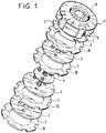
- Figure 1 is a partial exploded perspective view of a multi-plate clutch with structural discs.
- Figure 2 is a partial perspective view of a first embodiment of a clutch according to the invention.
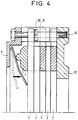
- Figures 3 and 4 are half-sectional views of such a clutch, in the disengaged position and in the engaged position.
- Figure 5 is a partial perspective view of a second embodiment of a clutch according to the invention.
- Figure 6 is a partial perspective view of a third embodiment of a clutch according to the invention.
- Figure 7 is a half sectional view of such a clutch, in the disengaged position.
- FIG. 1 represents certain parts of a known clutch known as a three-plate clutch (by analogy to conventional clutches with organic linings).
- a driving disc 2 called first driving disc
- three driven discs 3 connected to an output shaft by a hub 4
- a driving disc 5 being interposed between each pair of driven discs 3
- a driving disc 6 called second driving disc
- a pressure plate 7 and a cover 8 comprising an actuable mechanism for pushing the plate 7 and provided with balusters 9 housed in radial notches 10 of the driving discs 2,3,6 and fixed to the steering wheel by a screw housed in a bore 11 of each baluster 9 and screwed into the steering wheel .
- the balusters 9 can either be part of the cover 8, or be fixed thereto by screwing or the like.
- FIGS. 2, 3 and 4 A first variant is shown in FIGS. 2, 3 and 4.
- FIG. 2 for the sake of clarity, only the driving discs 2,5,6 and a baluster 9 are shown.
- a so-called plating device 30 consists of two elastic metal blades disposed on each side of the baluster 9. The fixing end of each blade is connected by riveting on the lateral face of the baluster 9, between the second driving disc 6 and the nearest drive disc 5 and its active end curved by about 90 ° relative to the fixing end presses the second disc 6 against the plate 8.
- Figure 4 shows the clutch in the engaged position.
- the distribution of the play is maximized at the active interfaces and this results in better release on disengaging.
- the compression or clutching is done in a perfectly uniform manner, without parasitic interaction at the level of the flywheel interfaces - first driving disc and plate - second driving disc.
- FIG. 5 A second variant is shown in FIG. 5.
- the plating device 30 is here produced from a single piece by folding, the two elastic blades 31 being connected by a central blade 32 forming a U with the flat parts of the blades 31 placed against the lateral faces of the baluster 9. This blade 32 is arranged against the inner face of the baluster 9 and is fixed there by riveting.
- FIGS. 6 and 7 require a particular arrangement of the baluster 9 and of the second driving disc 6.
- the second driving disc 6 instead of the conventional notch has two notches 6 'of smaller dimension receiving the branches of the baluster 9 in U. A receiving orifice for the screw 14 is provided between these two notches 6'.
- the plating device consists of a folded blade comprising a section 40 disposed against the outer face of the baluster 9 and a section 31 of plating forming a curved elastic blade pushing the second driving disc 6 by its part lying between the notches 6 'and provided with a hole for the passage of the screw 14.
- the arrangements described above can be mounted on all the balusters 9 of the clutch or not.
- the plating blades must be sufficient to eliminate any play between the platter and the second disc.
- the plating device is mounted in the plate / second drive disc interface
- the plating device 30 shown in FIGS. 2 to 7 can be mounted between the driving disc 6 and the plate 7 and / or between the driving disc 2 and the flywheel 12.
Landscapes
- Engineering & Computer Science (AREA)
- General Engineering & Computer Science (AREA)
- Mechanical Engineering (AREA)
- Mechanical Operated Clutches (AREA)
- Carbon And Carbon Compounds (AREA)
- Ceramic Products (AREA)
- Connection Of Motors, Electrical Generators, Mechanical Devices, And The Like (AREA)
- Chemically Coating (AREA)
Claims (6)
- Kupplung mit strukturellen Reibungsscheiben, insbesondere auf Karbon-Karbon-Basis,- mit einem motorseitigen Schwungrad (12),- mit einer ersten Antriebsscheibe (2), die einen ersten nicht aktiven Übergang zwischen sich und dem Schwungrad (12) bildet,- mit mindestens einer angetriebenen Scheibe (3), die mit einer Ausgangswelle verbunden ist, wobei ggf. eine Antriebsscheibe (5) zwischen jedem eventuellen benachbarten Paar von angetriebenen Scheiben (3) liegt,- mit einer zweiten Antriebsscheibe (6),- mit einer Anpreßplatte (7), die einen zweiten nicht aktiven Übergang zwischen sich und der zweiten Antriebsscheibe (6) bildet,- und mit einem Deckel (8), der einen Betätigungsmechanismus zum Anpressen der Platte (7) sowie Säulen (9) enthält, die in radialen Nuten (10) der Antriebsscheiben (2, 5, 6) liegen und am Schwungrad (12) befestigt sind, dadurch gekennzeichnet, daß die Kupplung eine Anpreßvorrichtung (30) enthält, die den Abstand an mindestens einem der nicht aktiven Übergänge beseitigt und ein Mittel zum Anpressen der Antriebsscheibe (2, 6) an das benachbarte Bauteil (7, 12) enthält.
- Kupplung nach Anspruch 1, dadurch gekennzeichnet, daß die Anpreßvorrichtung (30) mindestens eine elastische Metallamelle (31) enthält, die zwischen der Antriebsscheibe (2, 6) des Übergangs und der nächstliegenden angetriebenen Scheibe (5) liegt und deren aktives gekrümmtes Ende die Scheibe (2, 6) des Übergangs gegen das benachbarte Bauteil (7, 12) drückt.
- Kupplung nach Anspruch 2, dadurch gekennzeichnet, daß die Anpreßvorrichtung (30) zwei elastische Lamellen (31) enthält, deren Befestigungsende an den Außenseiten der Säule (9) anliegt.
- Kupplung nach Anspruch 3, dadurch gekennzeichnet, daß die beiden elastischen Lamellen (31) über eine zentrale Lamelle (32) miteinander verbunden sind, die an der Innenseite der Säule (9) liegt.
- Kupplung nach Anspruch 2, dadurch gekennzeichnet, daß die Säulen (9) U-förmig ausgebildet sind und eine Öffnung (9') auf der Seite des Bauteils (7, 12) des Übergangs besitzen, und daß die Antriebsscheibe (2, 6) zwei Nuten (6') aufweist, in der die Zweige der Säule (9) liegen, während die Lamelle (31) in der Öffnung (9') liegt und die Antriebsscheibe (2, 6) zwischen die Nuten (6') drückt.
- Kupplung nach Anspruch 5, dadurch gekennzeichnet, daß die Lamelle (31) durch einen Lamellenabschnitt (40) verlängert ist, der an der Außenseite der Säule (9) liegt und eine Öffnung für das Befestigungsmittel des Deckels auf dem Schwungrad (12) besitzt.
Applications Claiming Priority (2)
| Application Number | Priority Date | Filing Date | Title |
|---|---|---|---|
| FR9112431 | 1991-10-09 | ||
| FR9112431A FR2682440B1 (fr) | 1991-10-09 | 1991-10-09 | Embrayage a disques structuraux en particulier en carbone-carbone. |
Publications (3)
| Publication Number | Publication Date |
|---|---|
| EP0537087A2 EP0537087A2 (de) | 1993-04-14 |
| EP0537087A3 EP0537087A3 (en) | 1993-11-24 |
| EP0537087B1 true EP0537087B1 (de) | 1996-01-03 |
Family
ID=9417743
Family Applications (1)
| Application Number | Title | Priority Date | Filing Date |
|---|---|---|---|
| EP92420343A Expired - Lifetime EP0537087B1 (de) | 1991-10-09 | 1992-10-01 | Kupplung mit Verbundscheiben, insbesondere aus Kohlenstoff-Kohlenstoff-Verbundwerkstoff |
Country Status (7)
| Country | Link |
|---|---|
| US (1) | US5325948A (de) |
| EP (1) | EP0537087B1 (de) |
| JP (1) | JP2615327B2 (de) |
| AT (1) | ATE132588T1 (de) |
| DE (1) | DE69207327T2 (de) |
| ES (1) | ES2081594T3 (de) |
| FR (1) | FR2682440B1 (de) |
Families Citing this family (6)
| Publication number | Priority date | Publication date | Assignee | Title |
|---|---|---|---|---|
| JP3515667B2 (ja) * | 1996-07-17 | 2004-04-05 | 株式会社エクセディ | クラッチカバー組立体 |
| US5715918A (en) * | 1996-09-30 | 1998-02-10 | Ford Global Technologies, Inc. | Elastically latched and staked assembly in a kinematic arrangement of an automatic transmission |
| GB9705111D0 (en) * | 1997-03-12 | 1997-04-30 | Automotive Products Plc | A friction clutch |
| DE10148776C1 (de) * | 2001-10-02 | 2003-06-12 | Voith Turbo Kg | Montierbare Lamellenpaketeinheit und Verfahren zur Montage |
| US20090127053A1 (en) * | 2007-11-20 | 2009-05-21 | Nosakowski Brian M | Coupling assembly including retainers for holding coupling components within a housing |
| ITRE20120004A1 (it) * | 2012-01-30 | 2013-07-31 | Francesco Marte | Frizione meccanica multidisco normalmente disinnestata |
Family Cites Families (11)
| Publication number | Priority date | Publication date | Assignee | Title |
|---|---|---|---|---|
| US2036005A (en) * | 1933-05-25 | 1936-03-31 | Ernest E Wemp | Clutch structure |
| US2600520A (en) * | 1948-10-16 | 1952-06-17 | Lipe Rollway Corp | Friction disk separator for double disk clutches |
| JPS5846229A (ja) * | 1981-09-11 | 1983-03-17 | Honda Motor Co Ltd | 摩擦クラツチ |
| US4466524A (en) * | 1982-03-24 | 1984-08-21 | Dana Corporation | Plate locating apparatus for multiple disc clutch |
| FR2553482B1 (fr) * | 1983-10-18 | 1986-02-21 | Valeo | Ensemble rotatif multidisque a elements elastiques d'ecartement deformables, en particulier embrayage, notamment pour vehicule agricole |
| DE8533270U1 (de) * | 1985-11-26 | 1987-04-09 | J.M. Voith Gmbh, 7920 Heidenheim | Lamellenkupplung |
| US4846326A (en) * | 1987-11-27 | 1989-07-11 | Tilton Mclane | Carbon to carbon friction clutch |
| JPH0194627U (de) * | 1987-12-16 | 1989-06-22 | ||
| IT1245968B (it) * | 1990-05-31 | 1994-11-07 | Valeo | Innesto a piu' dischi di frizione in particolare per autoveicoli. |
| FR2662766B1 (fr) * | 1990-05-31 | 1995-04-14 | Valeo | Embrayage a plateau de pression associe a un disque intercalaire. |
| AU632418B2 (en) * | 1990-12-11 | 1992-12-24 | Fuji Tekko Co. Ltd. | Wet multiple disk clutch apparatus which is used in vehicles |
-
1991
- 1991-10-09 FR FR9112431A patent/FR2682440B1/fr not_active Expired - Fee Related
-
1992
- 1992-10-01 AT AT92420343T patent/ATE132588T1/de active
- 1992-10-01 ES ES92420343T patent/ES2081594T3/es not_active Expired - Lifetime
- 1992-10-01 EP EP92420343A patent/EP0537087B1/de not_active Expired - Lifetime
- 1992-10-01 DE DE69207327T patent/DE69207327T2/de not_active Expired - Fee Related
- 1992-10-05 US US07/956,311 patent/US5325948A/en not_active Expired - Fee Related
- 1992-10-08 JP JP4296491A patent/JP2615327B2/ja not_active Expired - Lifetime
Also Published As
| Publication number | Publication date |
|---|---|
| DE69207327D1 (de) | 1996-02-15 |
| JPH05280555A (ja) | 1993-10-26 |
| ES2081594T3 (es) | 1996-03-16 |
| JP2615327B2 (ja) | 1997-05-28 |
| EP0537087A3 (en) | 1993-11-24 |
| ATE132588T1 (de) | 1996-01-15 |
| US5325948A (en) | 1994-07-05 |
| FR2682440A1 (fr) | 1993-04-16 |
| DE69207327T2 (de) | 1996-05-15 |
| FR2682440B1 (fr) | 1993-11-19 |
| EP0537087A2 (de) | 1993-04-14 |
Similar Documents
| Publication | Publication Date | Title |
|---|---|---|
| EP0537088B1 (de) | Kupplung mit Verbundscheiben, insbesondere aus Kohlenstoff-Kohlenstoff-Verbundwerkstoff | |
| EP0537087B1 (de) | Kupplung mit Verbundscheiben, insbesondere aus Kohlenstoff-Kohlenstoff-Verbundwerkstoff | |
| FR2553482A1 (fr) | Ensemble rotatif multidisque a elements elastiques d'ecartement deformables, en particulier embrayage, notamment pour vehicule agricole | |
| EP0228310A1 (de) | Tellerfederkupplungsmechanismus, insbesondere für Kraftfahrzeuge und entsprechende Kupplung | |
| EP0857263A1 (de) | Reibungskupplung für kraftfahrzeuge mit einer verschleiss-nachstelleinrichtung | |
| FR2544037A1 (fr) | Butee de debrayage, notamment pour vehicule automobile | |
| FR2746153A1 (fr) | Embrayage a friction de vehicule automobile a compensation automatique de jeu | |
| FR2594918A1 (fr) | Embrayage type-traction | |
| FR2548302A1 (fr) | Frein multidisque perfectionne | |
| FR2549552A1 (fr) | Embrayage | |
| EP0172099B1 (de) | Drehschwingungsdämpfer mit einem Zentrierlager in zwei Teilen, insbesondere für Brennkraftmaschine | |
| FR2498710A1 (fr) | Frein a disque pour motocycle | |
| FR2689191A1 (fr) | Friction d'embrayage, notamment pour véhicule industriel. | |
| FR2662765A1 (fr) | Embrayage a plusieurs disques de friction, notamment pour vehicules automobiles. | |
| FR2550835A1 (fr) | Embrayage a friction | |
| FR2731056A1 (fr) | Embrayage a friction de vehicule automobile, a compensation automatique de l'usure | |
| FR2745869A1 (fr) | Dispositif d'embrayage a couvercle comportant un ressort a diaphragme et un ressort de sollicitation auxiliaire fonctionnant en tandem | |
| FR2598760A1 (fr) | Dispositif d'accouplement | |
| WO2000039474A1 (fr) | Embrayage a friction a dispositif de rattrapage d'usure des garnitures de friction, en particulier pour vehicule automobile | |
| EP0779446A1 (de) | Elastische Einheit mit ringförmigen Elementen und mit einer solchen Einheit ausgerüsteter Kupplungsmechanismus | |
| EP0678169B1 (de) | Kupplungsanordnung insbesondere für kraftfahrzeuge | |
| EP0819864B1 (de) | Kompakte Synchronisiereinrichtung für ein Zahnradwechselgetriebe, insbesondere für ein Kraftfahrzeug | |
| WO2000058641A1 (fr) | Embrayage a friction a dispositif de rattrapage d'usure des garnitures de friction, en particulier pour vehicule automobile | |
| FR2741682A1 (fr) | Dispositif de debrayage pour un embrayage a traction | |
| FR2763107A1 (fr) | Embrayage a friction |
Legal Events
| Date | Code | Title | Description |
|---|---|---|---|
| PUAI | Public reference made under article 153(3) epc to a published international application that has entered the european phase |
Free format text: ORIGINAL CODE: 0009012 |
|
| AK | Designated contracting states |
Kind code of ref document: A2 Designated state(s): AT BE CH DE DK ES FR GB GR IE IT LI LU MC NL PT SE |
|
| PUAL | Search report despatched |
Free format text: ORIGINAL CODE: 0009013 |
|
| AK | Designated contracting states |
Kind code of ref document: A3 Designated state(s): AT BE CH DE DK ES FR GB GR IE IT LI LU MC NL PT SE |
|
| 17P | Request for examination filed |
Effective date: 19940328 |
|
| 17Q | First examination report despatched |
Effective date: 19941117 |
|
| GRAA | (expected) grant |
Free format text: ORIGINAL CODE: 0009210 |
|
| AK | Designated contracting states |
Kind code of ref document: B1 Designated state(s): AT BE CH DE DK ES FR GB GR IE IT LI LU MC NL PT SE |
|
| PG25 | Lapsed in a contracting state [announced via postgrant information from national office to epo] |
Ref country code: NL Free format text: LAPSE BECAUSE OF FAILURE TO SUBMIT A TRANSLATION OF THE DESCRIPTION OR TO PAY THE FEE WITHIN THE PRESCRIBED TIME-LIMIT Effective date: 19960103 Ref country code: GR Free format text: LAPSE BECAUSE OF FAILURE TO SUBMIT A TRANSLATION OF THE DESCRIPTION OR TO PAY THE FEE WITHIN THE PRESCRIBED TIME-LIMIT Effective date: 19960103 Ref country code: DK Effective date: 19960103 Ref country code: AT Effective date: 19960103 |
|
| REF | Corresponds to: |
Ref document number: 132588 Country of ref document: AT Date of ref document: 19960115 Kind code of ref document: T |
|
| ITF | It: translation for a ep patent filed | ||
| REG | Reference to a national code |
Ref country code: IE Ref legal event code: FG4D Free format text: 66764 |
|
| REF | Corresponds to: |
Ref document number: 69207327 Country of ref document: DE Date of ref document: 19960215 |
|
| REG | Reference to a national code |
Ref country code: ES Ref legal event code: FG2A Ref document number: 2081594 Country of ref document: ES Kind code of ref document: T3 |
|
| PG25 | Lapsed in a contracting state [announced via postgrant information from national office to epo] |
Ref country code: PT Effective date: 19960403 |
|
| GBT | Gb: translation of ep patent filed (gb section 77(6)(a)/1977) |
Effective date: 19960326 |
|
| NLV1 | Nl: lapsed or annulled due to failure to fulfill the requirements of art. 29p and 29m of the patents act | ||
| PG25 | Lapsed in a contracting state [announced via postgrant information from national office to epo] |
Ref country code: IE Free format text: LAPSE BECAUSE OF NON-PAYMENT OF DUE FEES Effective date: 19960815 |
|
| REG | Reference to a national code |
Ref country code: IE Ref legal event code: FD4D Ref document number: 66764 Country of ref document: IE |
|
| PG25 | Lapsed in a contracting state [announced via postgrant information from national office to epo] |
Ref country code: LU Free format text: LAPSE BECAUSE OF NON-PAYMENT OF DUE FEES Effective date: 19961031 Ref country code: LI Effective date: 19961031 Ref country code: CH Effective date: 19961031 |
|
| PLBE | No opposition filed within time limit |
Free format text: ORIGINAL CODE: 0009261 |
|
| 26N | No opposition filed | ||
| PG25 | Lapsed in a contracting state [announced via postgrant information from national office to epo] |
Ref country code: MC Effective date: 19970430 |
|
| REG | Reference to a national code |
Ref country code: CH Ref legal event code: PL |
|
| PGFP | Annual fee paid to national office [announced via postgrant information from national office to epo] |
Ref country code: DE Payment date: 19971023 Year of fee payment: 6 |
|
| PGFP | Annual fee paid to national office [announced via postgrant information from national office to epo] |
Ref country code: SE Payment date: 19971027 Year of fee payment: 6 |
|
| PGFP | Annual fee paid to national office [announced via postgrant information from national office to epo] |
Ref country code: FR Payment date: 19971031 Year of fee payment: 6 |
|
| PGFP | Annual fee paid to national office [announced via postgrant information from national office to epo] |
Ref country code: BE Payment date: 19971118 Year of fee payment: 6 |
|
| PGFP | Annual fee paid to national office [announced via postgrant information from national office to epo] |
Ref country code: GB Payment date: 19981001 Year of fee payment: 7 |
|
| PG25 | Lapsed in a contracting state [announced via postgrant information from national office to epo] |
Ref country code: SE Free format text: LAPSE BECAUSE OF NON-PAYMENT OF DUE FEES Effective date: 19981002 |
|
| PGFP | Annual fee paid to national office [announced via postgrant information from national office to epo] |
Ref country code: ES Payment date: 19981014 Year of fee payment: 7 |
|
| PG25 | Lapsed in a contracting state [announced via postgrant information from national office to epo] |
Ref country code: BE Free format text: LAPSE BECAUSE OF NON-PAYMENT OF DUE FEES Effective date: 19981031 |
|
| REG | Reference to a national code |
Ref country code: FR Ref legal event code: TP |
|
| BERE | Be: lapsed |
Owner name: S.A. CARBONE INDUSTRIE Effective date: 19981031 |
|
| EUG | Se: european patent has lapsed |
Ref document number: 92420343.3 |
|
| PG25 | Lapsed in a contracting state [announced via postgrant information from national office to epo] |
Ref country code: FR Free format text: LAPSE BECAUSE OF NON-PAYMENT OF DUE FEES Effective date: 19990630 |
|
| REG | Reference to a national code |
Ref country code: FR Ref legal event code: ST |
|
| PG25 | Lapsed in a contracting state [announced via postgrant information from national office to epo] |
Ref country code: DE Free format text: LAPSE BECAUSE OF NON-PAYMENT OF DUE FEES Effective date: 19990803 |
|
| PG25 | Lapsed in a contracting state [announced via postgrant information from national office to epo] |
Ref country code: GB Free format text: LAPSE BECAUSE OF NON-PAYMENT OF DUE FEES Effective date: 19991001 |
|
| PG25 | Lapsed in a contracting state [announced via postgrant information from national office to epo] |
Ref country code: ES Free format text: LAPSE BECAUSE OF NON-PAYMENT OF DUE FEES Effective date: 19991002 |
|
| GBPC | Gb: european patent ceased through non-payment of renewal fee |
Effective date: 19991001 |
|
| REG | Reference to a national code |
Ref country code: ES Ref legal event code: FD2A Effective date: 20001113 |
|
| PG25 | Lapsed in a contracting state [announced via postgrant information from national office to epo] |
Ref country code: IT Free format text: LAPSE BECAUSE OF NON-PAYMENT OF DUE FEES;WARNING: LAPSES OF ITALIAN PATENTS WITH EFFECTIVE DATE BEFORE 2007 MAY HAVE OCCURRED AT ANY TIME BEFORE 2007. THE CORRECT EFFECTIVE DATE MAY BE DIFFERENT FROM THE ONE RECORDED. Effective date: 20051001 |