EP0537206B1 - Detektion der gefahr von vereisung für flugzeuge - Google Patents
Detektion der gefahr von vereisung für flugzeuge Download PDFInfo
- Publication number
- EP0537206B1 EP0537206B1 EP91911514A EP91911514A EP0537206B1 EP 0537206 B1 EP0537206 B1 EP 0537206B1 EP 91911514 A EP91911514 A EP 91911514A EP 91911514 A EP91911514 A EP 91911514A EP 0537206 B1 EP0537206 B1 EP 0537206B1
- Authority
- EP
- European Patent Office
- Prior art keywords
- liquid water
- region
- aircraft
- signals
- power
- Prior art date
- Legal status (The legal status is an assumption and is not a legal conclusion. Google has not performed a legal analysis and makes no representation as to the accuracy of the status listed.)
- Expired - Lifetime
Links
- 238000001514 detection method Methods 0.000 title abstract description 5
- XLYOFNOQVPJJNP-UHFFFAOYSA-N water Substances O XLYOFNOQVPJJNP-UHFFFAOYSA-N 0.000 claims abstract description 134
- 239000007788 liquid Substances 0.000 claims abstract description 77
- 239000013526 supercooled liquid Substances 0.000 claims abstract description 6
- 238000000034 method Methods 0.000 claims description 12
- 230000005540 biological transmission Effects 0.000 claims description 2
- 230000011664 signaling Effects 0.000 claims 6
- 230000001747 exhibiting effect Effects 0.000 claims 1
- 230000015572 biosynthetic process Effects 0.000 abstract 1
- 230000009977 dual effect Effects 0.000 abstract 1
- 239000013078 crystal Substances 0.000 description 39
- 239000012071 phase Substances 0.000 description 13
- 231100001261 hazardous Toxicity 0.000 description 8
- 230000002238 attenuated effect Effects 0.000 description 7
- 230000008859 change Effects 0.000 description 7
- 239000002245 particle Substances 0.000 description 6
- 238000009833 condensation Methods 0.000 description 5
- 230000005494 condensation Effects 0.000 description 5
- 239000000203 mixture Substances 0.000 description 4
- 230000000694 effects Effects 0.000 description 3
- 230000014509 gene expression Effects 0.000 description 3
- 206010000369 Accident Diseases 0.000 description 2
- 238000010521 absorption reaction Methods 0.000 description 2
- 239000011248 coating agent Substances 0.000 description 2
- 238000000576 coating method Methods 0.000 description 2
- 238000001556 precipitation Methods 0.000 description 2
- 230000001902 propagating effect Effects 0.000 description 2
- 239000007787 solid Substances 0.000 description 2
- 230000000007 visual effect Effects 0.000 description 2
- 208000027418 Wounds and injury Diseases 0.000 description 1
- 230000002411 adverse Effects 0.000 description 1
- 239000012080 ambient air Substances 0.000 description 1
- 238000009529 body temperature measurement Methods 0.000 description 1
- 230000006378 damage Effects 0.000 description 1
- 230000001627 detrimental effect Effects 0.000 description 1
- 238000010586 diagram Methods 0.000 description 1
- 238000003384 imaging method Methods 0.000 description 1
- 208000014674 injury Diseases 0.000 description 1
- 230000002045 lasting effect Effects 0.000 description 1
- 238000004519 manufacturing process Methods 0.000 description 1
- 230000007246 mechanism Effects 0.000 description 1
- 230000008569 process Effects 0.000 description 1
- 230000035945 sensitivity Effects 0.000 description 1
- 238000001228 spectrum Methods 0.000 description 1
- 238000010408 sweeping Methods 0.000 description 1
- 230000001960 triggered effect Effects 0.000 description 1
- 239000012808 vapor phase Substances 0.000 description 1
Images


Classifications
-
- G—PHYSICS
- G01—MEASURING; TESTING
- G01S—RADIO DIRECTION-FINDING; RADIO NAVIGATION; DETERMINING DISTANCE OR VELOCITY BY USE OF RADIO WAVES; LOCATING OR PRESENCE-DETECTING BY USE OF THE REFLECTION OR RERADIATION OF RADIO WAVES; ANALOGOUS ARRANGEMENTS USING OTHER WAVES
- G01S13/00—Systems using the reflection or reradiation of radio waves, e.g. radar systems; Analogous systems using reflection or reradiation of waves whose nature or wavelength is irrelevant or unspecified
- G01S13/88—Radar or analogous systems specially adapted for specific applications
- G01S13/95—Radar or analogous systems specially adapted for specific applications for meteorological use
- G01S13/953—Radar or analogous systems specially adapted for specific applications for meteorological use mounted on aircraft
-
- G—PHYSICS
- G01—MEASURING; TESTING
- G01S—RADIO DIRECTION-FINDING; RADIO NAVIGATION; DETERMINING DISTANCE OR VELOCITY BY USE OF RADIO WAVES; LOCATING OR PRESENCE-DETECTING BY USE OF THE REFLECTION OR RERADIATION OF RADIO WAVES; ANALOGOUS ARRANGEMENTS USING OTHER WAVES
- G01S13/00—Systems using the reflection or reradiation of radio waves, e.g. radar systems; Analogous systems using reflection or reradiation of waves whose nature or wavelength is irrelevant or unspecified
- G01S13/02—Systems using reflection of radio waves, e.g. primary radar systems; Analogous systems
- G01S13/06—Systems determining position data of a target
- G01S13/08—Systems for measuring distance only
- G01S13/10—Systems for measuring distance only using transmission of interrupted, pulse modulated waves
- G01S13/106—Systems for measuring distance only using transmission of interrupted, pulse modulated waves using transmission of pulses having some particular characteristics
-
- Y—GENERAL TAGGING OF NEW TECHNOLOGICAL DEVELOPMENTS; GENERAL TAGGING OF CROSS-SECTIONAL TECHNOLOGIES SPANNING OVER SEVERAL SECTIONS OF THE IPC; TECHNICAL SUBJECTS COVERED BY FORMER USPC CROSS-REFERENCE ART COLLECTIONS [XRACs] AND DIGESTS
- Y02—TECHNOLOGIES OR APPLICATIONS FOR MITIGATION OR ADAPTATION AGAINST CLIMATE CHANGE
- Y02A—TECHNOLOGIES FOR ADAPTATION TO CLIMATE CHANGE
- Y02A90/00—Technologies having an indirect contribution to adaptation to climate change
- Y02A90/10—Information and communication technologies [ICT] supporting adaptation to climate change, e.g. for weather forecasting or climate simulation
Definitions
- This invention relates to the detection of atmospheric conditions which would be likely to cause icing on the exposed surfaces of an aircraft such as the wings and tail surfaces. More particularly, the present invention relates to a method and apparatus for detecting super-cooled liquid water which is likely to create these icing conditions, through the use of a forward-looking dual-frequency radar system within the aircraft, thereby providing the aircraft pilot with an opportunity to avoid these potentially hazardous conditions.
- Super-cooled liquid water (SLW) droplets form in clouds when water vapor accumulates to saturation levels and condenses on cloud condensation nuclei at temperatures from 0° centigrade to minus forty degrees centigrade. SLW droplets grow by further condensation and by collisions with other drops and coalesce to sizes in excess of 100 micrometers, at which point the droplets begin to fall as precipitation. Over time, therefore, the spectrum of droplet size increases until there are many droplets of different sizes. SLW droplets eventually change to a vapor phase (evaporate) or to a solid (ice) phase (freeze), or they grow to a size sufficient to precipitate. The SLW droplets are a temporary phase, lasting anywhere from less than one minute to several hours.
- SLW droplets are formed in specific volumetric zones or regions within clouds.
- the region of SLW droplets may contain substantially only SLW droplets, or as is the more typical case, it may also contain ice crystals distributed throughout and mixed with the SLW droplets. In such circumstances, the region of SLW droplets and ice crystals is referred to as a mixed phase region.
- Ice crystals are less readily and less abundantly nucleated in the atmosphere than are liquid droplets. Therefore, at all but the coldest temperatures, SLW droplets will form before ice crystals. Ice crystals nucleate by several mechanisms, and the rate at which crystals nucleate is a complex function of the ice nuclei concentration, the temperature, the water droplet size distribution, and humidity.
- the amount of SLW in the region can increase by further condensation from a cloud updraft, for instance, causing the mixed phase region to change to a region which is predominantly or only SLW droplets.
- SLW droplets Sufficient quantities of SLW droplets in the flight path of an aircraft have the potential to adversely impact its flight performance.
- SLW droplets turn to ice on contact with all components of the aircraft exposed to the airstream and which are not in some way protected.
- a coating of ice on the leading edges of the wings reduces the amount of lift, increases the amount of drag, and, if the coating is substantial enough, may even cause the aircraft to crash.
- Statistics suggest the seriousness of aircraft icing incidents. An average of over 60 civilian lives appear to be lost every year due to icing related aircraft accidents. During a five and a half year period between 1978 and 1983, 280 icing-related aircraft accidents occurred with 364 fatalities and 161 injuries.
- no warning system is available to pilots to indicate those regions of SLW within clouds in time to divert the course of the aircraft, and to detect conditions which could create a risk of aircraft icing due to the existence of regions of SLW while distinguishing other conditions which pose no threat to aircraft.
- An airborne icing hazard detection system of the present invention offers the capability of providing information which distinguishes a region containing SLW droplets in clouds from a region containing ice crystals, even in a mixed phase cloud region. Information as to the size and location of the region containing SLW is presented to the aircraft pilot, to be used in making decisions regarding possible maneuvers to avoid the regions of SLW.
- an airborne, forward-looking, dual-frequency radar system is carried by the aircraft and is used to detect and indicate the size and location of regions of SLW droplets ahead of the aircraft in its flight path.
- the radar signal or beam at one frequency i.e. the higher frequency
- the radar signal or beam at the other frequency i.e. the lower frequency
- the influence of ice crystals on the two radar signals is relatively negligible, thereby allowing regions of liquid water droplets to be distinguished from ice crystals.
- the relative difference in attenuation is determined from sensing the respective strengths of the two signals propagating through and reflecting back from the region of liquid water droplets.
- the relative difference in attenuation of the two reflected signals is used to determine the existence of liquid water in the flight path of the aircraft.
- the atmospheric temperature ambient to the aircraft is also determined with an on-board temperature sensor. Because the ambient atmospheric temperature is nearly equal to the temperature in the cloud ahead of the aircraft at the same altitude within the effective range of the radar beams, the ambient temperature measurement is used to determine whether the region of detected liquid water ahead of the aircraft is SLW.
- the range derivative of the resulting difference in attenuation is calculated.
- the range derivative is proportional to the amount of SLW in the region ahead of the aircraft. From the range derivative, a determination is made whether the amount of liquid water is greater than a predetermined threshold which defines that amount which is enough to be of concern from an icing standpoint. When the amount of detected liquid water is above a predetermined threshold and the expected atmospheric temperature is below 0° centigrade, an indication is delivered of conditions which may give rise to a likelihood of hazardous icing conditions in the flight path of the aircraft.
- the size and location of the region of the hazardous icing conditions is also indicated, using conventional radar imaging and display techniques.
- the pilot By detecting the hazardous regions of SLW well in advance and providing information as to the size and location of the region of SLW, the pilot has an opportunity to avoid flying through the region of potentially hazardous icing conditions.
- IHD airborne Icing Hazard Detector
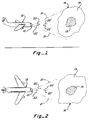
- Located in the present flight path of the aircraft 12 is a mixed phase cloud 16 containing an internal region 18 of SLW or a mixture of SLW and ice crystals, and a surrounding outer region 19 of only ice crystals.
- Two radar beams 20 and 22 are transmitted at different predetermined frequencies in pulsed form forward from the aircraft 12. The direction of transmission of the beams 20 and 22 is scanned in vertical and horizontal sectors in front of the aircraft, as is shown by the dashed lines 21 in Figures 1 and 2.
- the transmitted beams 20 and 22 are reflected and scattered by the cloud 16 and become reflected signals 20' and 22', respectively, which are returned to and received by the IHD 10.
- the received power of the two reflected signals 10' and 22' and a signal representative of the temperature ambient to the aircraft are evaluated by the IHD 10.
- the existence and quantity of SLW in the region 18 is determined to evaluate whether it poses an icing hazard, the ice crystals contained in the regions 18 and 19 are distinguished from the SLW contained in the region 18, and the size and location of the region 18 of SLW is indicated to the pilot of the aircraft 12. Since the temperature ambient at the aircraft will be substantially equivalent at the same altitude within the cloud 16 in general range of the radar beam, and because changes in temperature above and below the aircraft can usually be predicted based on the ambient temperature and a standard temperature change rate with altitude, the super-cooled nature of the detected liquid water can usually be reliably predicted.
- the expected operating range of the IHD is from about 100 meters in front of the aircraft to about 50 kilometers in front of the aircraft.
- the heart of the IHD is a computer or processor 23.
- the processor 23 sends signals to and receives signals from the other components of the IHD 10, processes data obtained from its input signals to obtain the information and supply the indications and displays of that information noted above and described in detail below.
- the processor 23 sends timing and control signals at 24 and 26 to trigger radar transmitters 28 and 30 to generate the radar beams 20 and 22 as pulses 32 and 34, respectively.
- transmitters 28 and 30 are triggered simultaneously.
- Each transmitter generates a radar beam at a different predetermined frequency than the other transmitter, and the power of the generated radar beam pulses 32 and 34 is at a predetermined level.
- the radar beam pulses 32 and 34 are delivered to a forward-pointing antenna 36 from which they are transmitted as the radar beams 20 and 22.
- the frequency of the beam 20 produced by transmitter 28 is preferably about 35 Gigahertz (GHz), referred to as the Ka band.
- the frequency of the beam 22 produced by transmitter 30 is preferably about 9.3 GHz, referred to as the X-band.
- the frequencies of the two beams 20 and 22 are selected to exhibit measurably different attenuation characteristics as the two signals propagate through liquid water in clouds, and relatively similar attenuation characteristics when propagating through regions of ice crystals.
- the frequencies of the two signals may vary from those preferred frequencies noted above, so long as these considerations are achieved and the received signals are sufficiently strong to be detectable, as described herein.
- the preferred frequencies noted above are desirable because they are commonly used radar frequencies and because they possess the desired attenuation characteristics. Furthermore, many aircraft currently have an X-band weather radar system with an antenna, which will allow the IHD of the present invention to be adapted to the aircraft by adding a Ka band radar that utilizes the same antenna and produces a Ka band beam pattern similar to the X-band beam pattern.
- the antenna 36 both transmits the beams 20 and 22 produced by the transmitters 28 and 30, respectively, and receives the reflected signals 20' and 22'.
- the antenna 36 can be swept vertically and horizontally to scan predetermined horizontal and vertical sectors shown by the dashed lines 21 ( Figures 1 and 2) in front of the aircraft.
- An antenna controller 37 receives control signals 38 from the processor 23 and responds through a conventional mechanical or electronic linkage, schematically represented at 39, to pivot or sweep the antenna 36 through the horizontal and vertical sectors. Since the processor 23 generates the control signals 38, the processor is able to obtain antenna angular information to enable calculation of the information necessary to create the plan position indicator and range height indicator displays typical of radars, and by which the size and location of the regions 18 of SLW are displayed to the pilot.
- the antenna 36 picks up the reflected signals 20' and 22' at the two different frequencies and supplies them to receivers 40 and 42, respectively.
- Output signals in the form of received signals 44 and 46 are supplied from the receivers 40 and 42, respectively, to the processor 23.
- the magnitudes of the received signals 44 and 46 relate to the power present in the two reflected signals 20' and 22', respectively.
- the processor also analyzes the two received signals to establish the information to create the range height and plan position displays in the typical manner.
- Figures 4C and 4D illustrate the characteristics of the two received signals which have been influenced by scattering from ice particles and the attenuation caused by the propagation through the liquid water region 18 of the cloud 16 shown in Figures 4A and 4B.
- the radar signals will be attenuated by propagation through the region 18, even though there is no reflected signal from this region to represent the attenuation.
- the amount of attenuation is represented by the decrease in power of the received signals reflected from the ice crystal portion of the far side of the cloud, shown by the range interval 48b, compared to the amount of power reflected from the beginning portion of the region 19, shown by the range interval 48a.
- the relative difference in power of the signals over the range intervals 48a and 48b when no change is apparent in the lower frequency signal shown in Figure 4D represents the attenuation by the pure liquid water in the region 18.
- the processor 23 ( Figure 3) determines the amount of this difference in power to establish the amount of attenuation attributable to the liquid water.
- the region 18 contains a mixture of liquid water and ice crystals
- those ice crystals will reflect a signal from the region 18, as is shown in Figure 4C by the dashed lines over the range interval 50.
- the slope of the dashed line curve represents the degree to which the liquid water in the region 18 attenuates the signal over the range interval 50.
- the amount of attenuation through the beginning and ending portions 48a and 48b of the region 19 is negligible because of the negligible attenuation of the signal by the ice crystals.
- Propagation of the lower frequency signals 22 and 22' through the beginning and ending portions of the region 19 of ice crystals shown at the range intervals 48a and 48b in Figure 4D, and through the region 18 of either liquid water or a mixture of liquid water and ice crystals results in little attenuation of the received signal 46.
- the lack of attenuation by either the ice crystals or the liquid water results simply from the negligible attenuation characteristics on the lower frequency radar beam.
- the liquid water within the region 18 over the range interval 50 absorbs more of the power from the higher frequency radar signal and results in a greater attenuation of it compared to the other lower frequency radar signal.
- the amount of attenuation which occurs depends on the amount of liquid water in the region 18 and the length of the range 50 through which the higher frequency signal propagates. The greater the range interval 50 through which the radar signal travels, the greater will be the total attenuation of the received signal.
- Differences in attenuation characteristics of the two radar signals allow the region 18 containing liquid water to be identified over the range interval 50 and also allows the region 19 of ice crystals to be identified over the range intervals 48a and 48b.
- the distinction between those regions composed solely of ice crystals and mixed phase regions is made possible by the negligible absorption of power at both frequencies when only ice crystals are present and by the significant differences in absorption of one of the two frequencies caused by the presence of liquid water.
- Attenuation of the Ka-band signal by liquid water is about ten times greater than is the X-band signal.
- Ice solid water causes attenuation of a much smaller amount for each frequency. For ice, the rate is 0.00291 dB per kilometer per gram per cubic meter for the Ka-band signal and 0.000891 dB per kilometer for the X-band signal.
- the attenuation caused by ice is therefore about two orders of magnitude less than that caused by liquid water. Consequently, the attenuation effect of ice is negligible for the purposes of this invention and clouds containing liquid water can be readily distinguish from clouds containing only ice crystals. It is the liquid water which may give rise to an icing hazard, since ice crystals in clouds do not collect on the wings and tail surfaces of an aircraft.
- the distance or range interval information and the angular information of the antenna obtained over the sweep allows the processor 23 (figure 3) to calculate information which defines the size and location of the region 18 in front of the aircraft.
- the size and location of the region 18 is preferably presented as the typical plan position indicator and range height indicator displays of a conventional radar.
- the processor 23 computes the difference in energy of the two received signals 44 and 46 at the different frequencies, as is illustrated by Figure 4E.
- the range derivative of this difference ( Figure 4E) with respect to distance is then calculated, as is illustrated by Figure 4F.
- the range derivative of the difference in attenuation between the two different frequency received signals is directly proportional to the quantity of liquid water ahead of the aircraft.
- the range derivative ( Figure 4F) enables the processor to distinguish between these situations where the quantity and range extent of SLW is sufficient to be regarded as a significant icing hazard, and those situations where there is an insufficient quantity of SLW or that its spatial distribution is too limited to represent an icing hazard.
- the calculations to establish the difference in received power and the average difference in power over the range interval of the region 18 are also accomplished by the processor, generally on an interpolation basis.
- M (4.38/D) log [P k (r) P x (r+D)/
- M is the mean liquid water content (in grams per cubic meter) between r and (r+D)
- P k is the power of the reflected signal of the strongly attenuated signal, e.g., the Ka band radar received signal 44
- P x is the power of the reflected signal of the weakly attenuated signal, i.e.
- r is the range of the SLW region in front of the aircraft
- D is the range interval 50 over which the value of M is averaged.
- This equation is one example of a numerical finite difference expression to approximate the range derivative. Other suitable mathematical expressions are also available to obtain the information necessary to practice the present invention.
- the outside ambient temperature is measured.
- the measured temperature is generally the same at the same altitude within the cloud ahead of the aircraft at the same altitude.
- the measured temperature is sued to determine whether the detected regions of liquid water in front of the aircraft will be super-cooled or not.
- a correction based on moist adiabatic lapse rate can be applied when the radar beam is not transmitted horizontally.
- the processor 23 receives an input temperature signal 52 from a temperature sensor 54.
- the temperature signal 52 is used by the processor 23 to determine if the outside ambient temperature at the present altitude of the aircraft is below 0° centigrade.
- the sensor 54 may be a known device for measuring temperature.
- Information from the temperature signal 52 and information concerning the moist adiabatic lapse rate is used by the processor 23 to estimate the temperature of clouds ahead of the aircraft at a different altitude when the region 18 is located with a vertically scanning antenna or as a result of a non-horizontal flight path as described above.
- the processor 23 will not signal an indication of a hazardous condition.
- the processor 23 determines if the detected amount of liquid water (Figure 4F) is greater than a predetermined threshold which is regarded as the minimum amount of SLW which will be detrimental to the aircraft.
- the predetermined threshold may vary according to the type of aircraft and equipment available on the aircraft to counteract icing. Furthermore, the threshold may vary depending on the length of the region of SLW, in that longer projected flight paths through the region of SLW might require a lower threshold. Comparison of the amount of detected liquid water to a threshold value assures that there are no false indications when the quantity of liquid water is insufficient in magnitude to create a significant hazard and when the ambient air temperature at the location of the region of SLW is above 0° centigrade.
- a signal 56 is sent to an indicator and display 58, as is shown in Figure 3.
- the signal 56 contains information which is interpreted by the indicator/display 58 to indicate an icing hazard.
- the signal 56 also contains information which the indicator/display 58 interprets to display or otherwise indicate the size and location of the region of SLW which creates the hazard and the regions of ice crystals, preferably in the typical radar plan position indicator and range height indicator formats.
- the indicator/display 58 may also present a full range of indications and warnings, such as an audible tone, a visual warning, and/or other visual and audible indications for the pilot.
- the information presented by the indicator/display should be sufficient to allow the pilot to make an informed decision regarding the risks associated with navigating the aircraft along the projected present flight path and along altered flight paths to avoid the icing hazards associated with SLW.
Landscapes
- Engineering & Computer Science (AREA)
- Radar, Positioning & Navigation (AREA)
- Remote Sensing (AREA)
- Physics & Mathematics (AREA)
- Computer Networks & Wireless Communication (AREA)
- General Physics & Mathematics (AREA)
- Aviation & Aerospace Engineering (AREA)
- Electromagnetism (AREA)
- Radar Systems Or Details Thereof (AREA)
- Geophysics And Detection Of Objects (AREA)
Claims (18)
- Vorrichtung zum Erfassen des Vorhandenseins einer unterkühltes flüssiges Wasser oder SLW enthaltenden Region in einer Wolke in dem Flugweg vor einem Luftfahrzeug, welche Vorrichtung umfaßt:Mittel zum Senden eines ersten Radarstrahlsignals mit einer ersten vorgegebenen Frequenz in die Wolke vor dem Luftfahrzeug;Mittel zum Senden eines zweiten Radarstrahlsignals mit einer zweiten vorgegebenen Frequenz in die Wolke vor dem Luftfahrzeug;wobei einer der Radarstrahlsignale mit der ersten oder der zweiten vorgegebenen Frequenz bedeutsam unterschiedliche Dämpfung bei Fortpflanzung des Signals durch die Flüssigwasserregion zeigt als das andere Radarstrahlsignal;Mittel zum jeweiligen Empfangen des ersten bzw. zweiten gesendeten Radarstrahlsignals nach Reflexion von der Wolke und zum jeweiligen Schaffen erster bzw. zweiter Reflexionssignale bei dem Luftfahrzeug, welche die erste bzw. die zweite vorgegebene Frequenz besitzen;Mittel, um die bei dem Luftfahrzeug empfangene Leistung des ersten bzw. zweiten Reflexionssignals als Funktion der Entfernung zu bestimmen und um erste und zweite empfangene Signale mit auf die Leistung der am Luftfahrzeug empfangenen Signale bezogenen Größen zuzuführen;Mittel, um die Umgebungstemperatur des Luftfahrzeugs zu erfassen und ein für die Umgebungstemperatur reprasentatives Temperatursignal zuzuführen;Prozessormittel, das auf die Sendung des ersten und des zweiten Radarstrahlsignals, den Empfang und die Größe des ersten und zweiten empfangenen Signals und das Temperatursignal reagiert zum:Errechnen der Leistungsdifferenz des ersten und des zweiten empfangenen Signals;Erfassen einer Region von Flüssigwasser aus der Leistungsdifferenz des ersten und des zweiten empfangenen Signals;Bestimmen, ob die Leistungsdifferenz des ersten und des zweiten empfangenen Signals einen vorgegebenen Schwellwertpegel übersteigt, der für eine Menge Flüssigwasser repräsentativ ist, die eine Vereisungsgefahr ergeben könnte;Benutzen des Temperatursignals, um zu bestimmen, ob die erfaßte Region von Flüssigwasser sich auf einer Temperatur in einem Bereich von 0°C und darunter befindet; undSignalisieren eines Vereisungsgefahr-Zustandes, falls die Differenz der Größen der ersten und zweiten empfangenen Signale die vorgegebene Schwelle übersteigt und die bestimmte Temperatur der erfaßten Flüssigwasserregion 0°C oder weniger beträgt.
- Vorrichtung nach Anspruch 1, bei der das Prozessormittel weiter die Menge des Flussigwassers bestimmt.
- Vorrichtung nach Anspruch 2, bei der das Prozessormittel die Menge von Flüssigwasser in dem Entfernungsbereich der erfaßten Flüssigwasserregion bestimmt.
- Vorrichtung nach Anspruch 2, bei der das Prozessormittel die Entfernungsableitung der Differenz der Leistung des ersten und des zweiten Empfangssignals errechnet, um die Menge Flüssigwasser über dem Längenintervall der erfaßten Flüssigwasserregion zu errechnen.
- Vorrichtung nach Anspruch 2, bei der das Prozessormittel die Leistungsdifferenz des ersten und des zweiten empfangenen Signals über dem Langenintervall der erfaßten Flüssigwasserregion interpoliert, um die Flüssigwassermenge über dem Längenintervall der erfaßten Flüssigwasserregion zu bestimmen.
- Vorrichtung nach Anspruch 4 und 5, welche weiter umfaßt: Anzeigemittel, das darauf reagiert, daß das Prozessormittel eine Vereisungsgefahr signalisiert, und zum Anzeigen der Vereisungsgefahr für einen Piloten des Luftfahrzeugs.
- Vorrichtung nach Anspruch 6, bei der das Anzeigemittel weiter den Ort der die Vereisungsgefahr zeigenden Region signalisiert.
- Vorrichtung nach Anspruch 6, bei der das Anzeigemittel weiter die Größe der die Vereisungsgefahr zeigenden Region signalisiert.
- Vorrichtung nach Anspruch 6, bei der das Anzeigemittel weiter die Größe und den Ort der Region signalisiert, welche die Vereisungsgefahr darstellt, durch Darstellen von Anzeigen des Planpositionsindikators und des Bereichshöhenindikators.
- Verfahren zum Erfassen der Anwesenheit einer unterkühltes flüssiges Wasser oder SLW enthaltenden Region in einem Flugweg vor einem Luftfahrzeug, welches Verfahren umfaßt:Aussenden eines ersten Radarstrahlsignals mit einer ersten vorgegebenen Frequenz in die Wolke vor dem Luftfahrzeug;Aussenden eines zweiten Radarstrahlsignals mit einer zweiten vorgegebenen Frequenz in die Wolke vor dem Luftfahrzeug;Auswählen der vorgegebenen Frequenzen der Radarstrahlsignale in der Weise, daß das erste Radarstrahlsignal bei Fortpflanzung des Signals durch die Flüssigwasserregion eine beträchtlich andere Dämpfung zeigt als das andere Radarstrahlsignal;jeweiliges Empfangen des von der Wolke reflektierten ersten bzw. zweiten ausgesendeten Radarstrahlsignals, um erste und zweite reflektierte Signale bei dem Luftfahrzeug zu schaffen, welche jeweils die erste bzw. zweite vorgegebene Frequenz besitzen;Bestimmen der Leistung des ersten und des zweiten an dem Luftfahrzeug empfangenen reflektierten Signals als Funktion des Abstandes und Zuführen erster und zweiter empfangener Signale mit Größen, die auf die Leistung der an dem Luftfahrzeug empfangenen Signale bezogen sind;Abfühlen der Umgebungstemperatur des Luftfahrzeugs und Liefern eines für die Umgebungstemperatur repräsentativen Temperatursignals;Errechnen der Leistungsdifferenz des ersten und zweiten empfangenen Signals;Erfassen einer Flüssigwasserregion aus der Leistungsdifferenz des ersten und des zweiten empfangenen Signals;Bestimmen, ob die Leistungsdifferenz des ersten und des zweiten empfangenen Signals einen vorbestimmten Schwellwertpegel übersteigt, der für eine Flüssigwassermenge repräsentativ ist, die eine Vereisungsgefahr ergeben könnte;Benutzen des Temperatursignals, um zu bestimmen, ob die erfaßte Flüssigwasserregion sich bei einer Temperatur in einem Bereich von 0°C und darunter befindet; undSignalisieren eines Vereisungsgefahr-Zustandes, falls die Differenz der Größen des ersten und des zweiten empfangenen Signals den vorbestimmten Schwellwert übersteigt und die bestimmte Temperatur der erfaßten Flüssigwasserregion 0°C oder darunter beträgt.
- Verfahren nach Anspruch 10, das weiter umfaßt: Bestimmen der Menge von flüssigem Wasser.
- Verfahren nach Anspruch 11, das weiter umfaßt: Bestimmen der Menge des flüssigen Wassers über der Erstreckung der erfaßten Flüssigwasserregion.
- Verfahren nach Anspruch 12, das weiter umfaßt: Errechnen des Abstandsdifferentials der Leistungsdifferenz des ersten und des zweiten empfangenen Signals, um die Menge flüssigen Wassers über den Längenintervall der erfaßten Flüssigwasserregion zu bestimmen.
- Verfahren nach Anspruch 11, das weiter umfaßt: Interpolieren der Leistungsdifferenz des ersten und des zweiten empfangenen Signals über dem Längenintervall der erfaßten Flüssigwasserregion, um die Flüssigwassermenge über dem Längenintervall der erfaßten Flüssigwasserregion zu bestimmen.
- Verfahren nach Anspruch 13 oder 14, das weiter umfaßt: Anzeigen der Vereisungsgefahr für einen Piloten des Luftfahrzeugs.
- Verfahren nach Anspruch 15, das weiter umfaßt: Signalisieren des Ortes der die Vereisungsgefahr bietenden Region.
- Verfahren nach Anspruch 15, das weiter umfaßt: Signalisieren der Größe der die Vereisungsgefahr bietenden Region.
- Verfahren nach Anspruch 15, das weiter umfaßt: Signalisieren der Größe und des Ortes der die Vereisungsgefahr bietenden Region durch Präsentieren je einer Planpositions-Indikator- und Bereichshöhen-Indikator-Anzeige.
Applications Claiming Priority (3)
| Application Number | Priority Date | Filing Date | Title |
|---|---|---|---|
| US07/515,487 US5028929A (en) | 1990-04-30 | 1990-04-30 | Icing hazard detection for aircraft |
| US515487 | 1990-04-30 | ||
| PCT/US1991/002527 WO1991017457A1 (en) | 1990-04-30 | 1991-04-12 | Icing hazard detection for aircraft |
Publications (3)
| Publication Number | Publication Date |
|---|---|
| EP0537206A4 EP0537206A4 (de) | 1993-03-04 |
| EP0537206A1 EP0537206A1 (de) | 1993-04-21 |
| EP0537206B1 true EP0537206B1 (de) | 1996-01-31 |
Family
ID=24051570
Family Applications (1)
| Application Number | Title | Priority Date | Filing Date |
|---|---|---|---|
| EP91911514A Expired - Lifetime EP0537206B1 (de) | 1990-04-30 | 1991-04-12 | Detektion der gefahr von vereisung für flugzeuge |
Country Status (6)
| Country | Link |
|---|---|
| US (1) | US5028929A (de) |
| EP (1) | EP0537206B1 (de) |
| JP (1) | JP2638301B2 (de) |
| AT (1) | ATE133793T1 (de) |
| DE (1) | DE69116873T2 (de) |
| WO (1) | WO1991017457A1 (de) |
Cited By (3)
| Publication number | Priority date | Publication date | Assignee | Title |
|---|---|---|---|---|
| US10336465B2 (en) | 2016-01-08 | 2019-07-02 | The Regents Of The University Of Michigan | Ice crystals and volcanic ash detection system |
| US10508952B1 (en) | 2018-10-31 | 2019-12-17 | The Regents Of The University Of Michigan | Optimum spectral bands for active vision systems |
| US10621865B2 (en) | 2018-03-29 | 2020-04-14 | The Regents Of The University Of Michigan | Road condition monitoring system |
Families Citing this family (50)
| Publication number | Priority date | Publication date | Assignee | Title |
|---|---|---|---|---|
| SG46261A1 (en) * | 1990-04-09 | 1998-02-20 | Commw Scient Ind Res Org | A detection system for use in an aircraft |
| AU8621591A (en) * | 1990-09-05 | 1992-03-30 | Turbulence Prediction Systems | Improved method and apparatus for detecting weather related events and the like and devices for use therewith |
| US5488375A (en) * | 1994-09-28 | 1996-01-30 | Alliedsignal Inc. | Airborne weather radar system with icing detection capabiliy |
| US5850619A (en) * | 1996-11-15 | 1998-12-15 | University Corporation For Atmospheric Research | Frozen precipitation accumlation alert system |
| US6125327A (en) * | 1997-01-15 | 2000-09-26 | Harris Corporation | System for identifying and generating geographic map display of aircraft icing conditions |
| FR2768122B1 (fr) * | 1997-09-09 | 1999-11-19 | Sextant Avionique | Dispositif optique de detection de conditions givrantes sur aeronef |
| US6166661A (en) * | 1999-01-22 | 2000-12-26 | Rockwell Collins, Inc. | System for detecting ice on an aircraft |
| US6546353B1 (en) | 1999-09-13 | 2003-04-08 | University Corporation For Atmospheric Research | Hot plate precipitation measuring system |
| US6489915B1 (en) * | 1999-11-11 | 2002-12-03 | Raytheon Company | Microwave icing avoidance system |
| US6377202B1 (en) | 2000-03-24 | 2002-04-23 | The United States Of America As Represented By The Secretary Of Commerce | Icing hazard avoidance system and method using dual-polarization airborne radar |
| US6536948B1 (en) * | 2000-08-24 | 2003-03-25 | University Corporation For Atmospheric Research | Determining temperature of a physical medium using remote measurement |
| US6819265B2 (en) * | 2002-08-22 | 2004-11-16 | Rosemount Aerospace Inc. | Advanced warning ice detection system for aircraft |
| US8902100B1 (en) | 2008-03-07 | 2014-12-02 | Rockwell Collins, Inc. | System and method for turbulence detection |
| NZ534673A (en) | 2004-08-12 | 2006-03-31 | Agres Ltd | Non-invasive sensor and method of use for measuring the temperature and composition of frozen food products |
| US7957853B2 (en) * | 2006-06-13 | 2011-06-07 | The Mitre Corporation | Flight restriction zone detection and avoidance |
| DE102006054320A1 (de) * | 2006-11-17 | 2008-05-21 | Robert Bosch Gmbh | Verfahren und Vorrichtung zum Erkennen von Niederschlag mittels Radar |
| EP2117926B1 (de) * | 2007-01-10 | 2018-12-26 | Sikorsky Aircraft Corporation | Eisgeschwindigkeitsmesser mit virtueller aspiration |
| US20080278371A1 (en) * | 2007-05-11 | 2008-11-13 | Honeywell International Inc. | Methods and systems for reducing acquisition time in airborne weather radar |
| US8265805B2 (en) * | 2007-11-11 | 2012-09-11 | The Boeing Company | Method and apparatus for detecting icing conditions for an aircraft |
| US9846230B1 (en) * | 2013-03-15 | 2017-12-19 | Rockwell Collins, Inc. | System and method for ice detection |
| US7605744B1 (en) * | 2008-06-03 | 2009-10-20 | Vaisala Oyj | Method for extension of unambiguous range and velocity of a weather radar |
| US7982658B2 (en) * | 2009-03-31 | 2011-07-19 | Honeywell International Inc. | Systems and methods for assessing weather in proximity to an airborne aircraft |
| SE534215C2 (sv) * | 2009-10-15 | 2011-06-07 | Totalfoersvarets Forskningsins | Anordning och metod för detektering av vattenflöde |
| SE535666C2 (sv) | 2011-03-11 | 2012-10-30 | Totalfoersvarets Forskningsins | Metod och anordning för genomsökning av rasmassor |
| US8947296B2 (en) * | 2011-12-15 | 2015-02-03 | GM Global Technology Operations LLC | Method and system for measuring a distance with narrowband radar |
| US9013332B2 (en) * | 2012-01-05 | 2015-04-21 | The Boeing Company | Laser-based supercooled large drop icing condition detection system |
| US9188700B2 (en) * | 2012-03-08 | 2015-11-17 | Honeywell International Inc. | System and method to identify regions of airspace having ice crystals using an onboard weather radar system |
| WO2014106269A1 (en) * | 2012-12-31 | 2014-07-03 | Telvent Dtn Llc | Airfoil icing controller apparatuses, methods and systems |
| US12159543B2 (en) | 2012-12-31 | 2024-12-03 | Dtn, Llc | Dynamic aircraft threat controller manager apparatuses, methods and systems |
| US9558672B2 (en) | 2012-12-31 | 2017-01-31 | Telvent Dtn Llc | Dynamic aircraft threat controller manager apparatuses, methods and systems |
| CA2896761C (en) | 2012-12-31 | 2023-08-22 | Telvent Dtn Llc | Dynamic turbulence engine controller apparatuses, methods and systems |
| US9116244B1 (en) | 2013-02-28 | 2015-08-25 | Rockwell Collins, Inc. | System for and method of weather phenomenon detection using multiple beams |
| WO2015060899A1 (en) | 2013-10-24 | 2015-04-30 | The Regents Of The University Of Michigan | Ice and supercooled water detection system |
| US9304081B2 (en) * | 2013-10-24 | 2016-04-05 | The Regents Of The University Of Michigan | Ice and water detection system |
| US10935693B2 (en) * | 2015-03-18 | 2021-03-02 | Honeywell International Inc. | Prediction of ice crystal presence in a volume of airspace |
| US9938017B2 (en) * | 2015-10-30 | 2018-04-10 | Ge Aviation Systems Llc | Enhancing engine performance to improve fuel consumption based on atmospheric rain conditions |
| US10106267B2 (en) | 2015-10-30 | 2018-10-23 | Ge Aviation Systems Llc | Enhancing engine performance to improve fuel consumption based on atmospheric ice particles |
| US10725173B2 (en) * | 2016-06-08 | 2020-07-28 | Rosemount Aerospace Inc. | Airborne ice detector using quasi-optical radar |
| US10816661B2 (en) | 2016-06-08 | 2020-10-27 | Rosemount Aerospace Inc. | Airborne ice detector using quasi-optical radar |
| US20180081364A1 (en) * | 2016-09-16 | 2018-03-22 | Honeywell International Inc. | Apparatus and method to detect and avoid particles |
| US9983112B1 (en) * | 2017-01-20 | 2018-05-29 | Rosemount Aerospace Inc. | Controlled sampling volume of clouds for measuring cloud parameters |
| US10955549B2 (en) | 2017-10-12 | 2021-03-23 | Honeywell International Inc. | Melting layer estimation by weather radar device |
| GB2574490A (en) * | 2017-11-22 | 2019-12-11 | Foster Miller Inc | Airborne wind profiling portable radar system and method |
| US10877150B2 (en) * | 2018-03-06 | 2020-12-29 | Honeywell International Inc. | Ice crystal detection by weather radar |
| CN112046761B (zh) * | 2020-08-04 | 2021-10-15 | 中国空气动力研究与发展中心计算空气动力研究所 | 一种基于统计检验和滤波的飞机结冰在线探测方法 |
| US11686742B2 (en) | 2020-11-20 | 2023-06-27 | Rosemount Aerospace Inc. | Laser airspeed measurement sensor incorporating reversion capability |
| US11851193B2 (en) | 2020-11-20 | 2023-12-26 | Rosemount Aerospace Inc. | Blended optical and vane synthetic air data architecture |
| US11787547B2 (en) | 2021-02-22 | 2023-10-17 | Honeywell International Inc. | Icing detection using temperature data from an external data source |
| US12481057B2 (en) * | 2021-07-01 | 2025-11-25 | Rockwell Collins, Inc. | Ice crystal detection and qualification using vertical weather cell structure |
| CN115423762B (zh) * | 2022-08-25 | 2023-11-07 | 河北省人工影响天气中心 | 基于机载探头组合粒子谱的过冷水反演方法 |
Family Cites Families (5)
| Publication number | Priority date | Publication date | Assignee | Title |
|---|---|---|---|---|
| US3665466A (en) * | 1970-03-20 | 1972-05-23 | Exxon Production Research Co | Determination of ice thickness |
| US4015257A (en) * | 1975-09-11 | 1977-03-29 | The United States Of America As Represented By The Secretary Of The Navy | Radar detection of turbulence in precipitation |
| US4050067A (en) * | 1976-04-21 | 1977-09-20 | Elmore Jr Ethelbert P | Airborne microwave path modeling system |
| US4075555A (en) * | 1977-03-25 | 1978-02-21 | Canadian Patents And Development Limited | Electronic phase comparison apparatus for the remote measurement of layer thickness |
| US4613938A (en) * | 1985-01-25 | 1986-09-23 | Hss Inc. | Present weather observing system utilizing particulate size and velocity measurements |
-
1990
- 1990-04-30 US US07/515,487 patent/US5028929A/en not_active Expired - Lifetime
-
1991
- 1991-04-12 JP JP3510137A patent/JP2638301B2/ja not_active Expired - Lifetime
- 1991-04-12 DE DE69116873T patent/DE69116873T2/de not_active Expired - Fee Related
- 1991-04-12 AT AT91911514T patent/ATE133793T1/de not_active IP Right Cessation
- 1991-04-12 WO PCT/US1991/002527 patent/WO1991017457A1/en not_active Ceased
- 1991-04-12 EP EP91911514A patent/EP0537206B1/de not_active Expired - Lifetime
Cited By (3)
| Publication number | Priority date | Publication date | Assignee | Title |
|---|---|---|---|---|
| US10336465B2 (en) | 2016-01-08 | 2019-07-02 | The Regents Of The University Of Michigan | Ice crystals and volcanic ash detection system |
| US10621865B2 (en) | 2018-03-29 | 2020-04-14 | The Regents Of The University Of Michigan | Road condition monitoring system |
| US10508952B1 (en) | 2018-10-31 | 2019-12-17 | The Regents Of The University Of Michigan | Optimum spectral bands for active vision systems |
Also Published As
| Publication number | Publication date |
|---|---|
| DE69116873D1 (de) | 1996-03-14 |
| ATE133793T1 (de) | 1996-02-15 |
| DE69116873T2 (de) | 1996-08-01 |
| WO1991017457A1 (en) | 1991-11-14 |
| EP0537206A4 (de) | 1993-03-04 |
| JP2638301B2 (ja) | 1997-08-06 |
| US5028929A (en) | 1991-07-02 |
| JPH05507148A (ja) | 1993-10-14 |
| EP0537206A1 (de) | 1993-04-21 |
Similar Documents
| Publication | Publication Date | Title |
|---|---|---|
| EP0537206B1 (de) | Detektion der gefahr von vereisung für flugzeuge | |
| US6377202B1 (en) | Icing hazard avoidance system and method using dual-polarization airborne radar | |
| US11933890B2 (en) | System and method for turbulence detection | |
| US10908278B2 (en) | System and method to identify regions of airspace having ice crystals using an onboard weather radar system | |
| US7541971B1 (en) | Automatic bright band detection and compensation | |
| US7109913B1 (en) | Airborne weather radar system and radar display | |
| US7880666B2 (en) | System for measuring turbulence remotely | |
| US7492305B1 (en) | Weather profile display system and method with uncertainty indication | |
| US20090177343A1 (en) | System and method for selectable weather object display | |
| EP2339373A2 (de) | Systeme und Verfahren zur Erschließung von Hagel und Blitz mithilfe eines Luftwetterradar-Volumenpuffers | |
| WO2001035119A2 (en) | Microwave icing avoidance system | |
| US9864055B1 (en) | Weather radar system and method for detecting a high altitude crystal cloud condition | |
| EP2966471A1 (de) | Anzeige mit vertikalem profil einschliesslich wetterblöcken | |
| US9823347B1 (en) | Weather radar system and method for high altitude crystal warning interface | |
| US6856396B2 (en) | Wind shear detection system | |
| EP3614125B1 (de) | Partikelsensorsystem und verfahren zum bestimmen der sicht für ein fahrzeug | |
| EP4047586B1 (de) | Vereisungsdetektion unter verwendung von temperaturdaten von einer externen datenquelle | |
| US8681021B1 (en) | System, apparatus, and method for generating a lateral meteorological profile on an aircraft display unit | |
| EP1311816B1 (de) | Bestimmung der temperatur in einem physikalischen medium mittels fernmessung | |
| RU2100824C1 (ru) | Способ формирования сигналов грозовой опасности | |
| JPH0295294A (ja) | 雨雪識別装置 | |
| Greneker | Technology for the detection of airborne intruders approaching the high-security, high-value asset |
Legal Events
| Date | Code | Title | Description |
|---|---|---|---|
| PUAI | Public reference made under article 153(3) epc to a published international application that has entered the european phase |
Free format text: ORIGINAL CODE: 0009012 |
|
| 17P | Request for examination filed |
Effective date: 19920922 |
|
| AK | Designated contracting states |
Kind code of ref document: A1 Designated state(s): AT BE CH DE DK ES FR GB GR IT LI LU NL SE |
|
| 17Q | First examination report despatched |
Effective date: 19950609 |
|
| GRAA | (expected) grant |
Free format text: ORIGINAL CODE: 0009210 |
|
| AK | Designated contracting states |
Kind code of ref document: B1 Designated state(s): AT BE CH DE DK ES FR GB GR IT LI LU NL SE |
|
| PG25 | Lapsed in a contracting state [announced via postgrant information from national office to epo] |
Ref country code: NL Free format text: LAPSE BECAUSE OF FAILURE TO SUBMIT A TRANSLATION OF THE DESCRIPTION OR TO PAY THE FEE WITHIN THE PRESCRIBED TIME-LIMIT Effective date: 19960131 Ref country code: LI Effective date: 19960131 Ref country code: GR Free format text: LAPSE BECAUSE OF FAILURE TO SUBMIT A TRANSLATION OF THE DESCRIPTION OR TO PAY THE FEE WITHIN THE PRESCRIBED TIME-LIMIT Effective date: 19960131 Ref country code: ES Free format text: THE PATENT HAS BEEN ANNULLED BY A DECISION OF A NATIONAL AUTHORITY Effective date: 19960131 Ref country code: DK Effective date: 19960131 Ref country code: CH Effective date: 19960131 Ref country code: BE Effective date: 19960131 Ref country code: AT Effective date: 19960131 |
|
| REF | Corresponds to: |
Ref document number: 133793 Country of ref document: AT Date of ref document: 19960215 Kind code of ref document: T |
|
| REF | Corresponds to: |
Ref document number: 69116873 Country of ref document: DE Date of ref document: 19960314 |
|
| ITF | It: translation for a ep patent filed | ||
| PG25 | Lapsed in a contracting state [announced via postgrant information from national office to epo] |
Ref country code: SE Effective date: 19960430 Ref country code: LU Free format text: LAPSE BECAUSE OF NON-PAYMENT OF DUE FEES Effective date: 19960430 |
|
| ET | Fr: translation filed | ||
| NLV1 | Nl: lapsed or annulled due to failure to fulfill the requirements of art. 29p and 29m of the patents act | ||
| REG | Reference to a national code |
Ref country code: CH Ref legal event code: PL |
|
| PLBE | No opposition filed within time limit |
Free format text: ORIGINAL CODE: 0009261 |
|
| STAA | Information on the status of an ep patent application or granted ep patent |
Free format text: STATUS: NO OPPOSITION FILED WITHIN TIME LIMIT |
|
| 26N | No opposition filed | ||
| PGFP | Annual fee paid to national office [announced via postgrant information from national office to epo] |
Ref country code: FR Payment date: 20000317 Year of fee payment: 10 |
|
| PGFP | Annual fee paid to national office [announced via postgrant information from national office to epo] |
Ref country code: DE Payment date: 20000320 Year of fee payment: 10 |
|
| PGFP | Annual fee paid to national office [announced via postgrant information from national office to epo] |
Ref country code: GB Payment date: 20000321 Year of fee payment: 10 |
|
| PG25 | Lapsed in a contracting state [announced via postgrant information from national office to epo] |
Ref country code: GB Free format text: LAPSE BECAUSE OF NON-PAYMENT OF DUE FEES Effective date: 20010412 |
|
| PG25 | Lapsed in a contracting state [announced via postgrant information from national office to epo] |
Ref country code: FR Free format text: THE PATENT HAS BEEN ANNULLED BY A DECISION OF A NATIONAL AUTHORITY Effective date: 20010430 |
|
| GBPC | Gb: european patent ceased through non-payment of renewal fee |
Effective date: 20010412 |
|
| PG25 | Lapsed in a contracting state [announced via postgrant information from national office to epo] |
Ref country code: DE Free format text: LAPSE BECAUSE OF NON-PAYMENT OF DUE FEES Effective date: 20020201 |
|
| REG | Reference to a national code |
Ref country code: FR Ref legal event code: ST |
|
| PG25 | Lapsed in a contracting state [announced via postgrant information from national office to epo] |
Ref country code: IT Free format text: LAPSE BECAUSE OF NON-PAYMENT OF DUE FEES;WARNING: LAPSES OF ITALIAN PATENTS WITH EFFECTIVE DATE BEFORE 2007 MAY HAVE OCCURRED AT ANY TIME BEFORE 2007. THE CORRECT EFFECTIVE DATE MAY BE DIFFERENT FROM THE ONE RECORDED. Effective date: 20050412 |