EP0537367A1 - Pressform und verfahren zum pressformen von thermoplastischen harzen unter verwendung dieser pressform - Google Patents
Pressform und verfahren zum pressformen von thermoplastischen harzen unter verwendung dieser pressform Download PDFInfo
- Publication number
- EP0537367A1 EP0537367A1 EP92909479A EP92909479A EP0537367A1 EP 0537367 A1 EP0537367 A1 EP 0537367A1 EP 92909479 A EP92909479 A EP 92909479A EP 92909479 A EP92909479 A EP 92909479A EP 0537367 A1 EP0537367 A1 EP 0537367A1
- Authority
- EP
- European Patent Office
- Prior art keywords
- mold
- nozzle
- resin
- molten resin
- thermoplastic resin
- Prior art date
- Legal status (The legal status is an assumption and is not a legal conclusion. Google has not performed a legal analysis and makes no representation as to the accuracy of the status listed.)
- Granted
Links
Images
Classifications
-
- B—PERFORMING OPERATIONS; TRANSPORTING
- B29—WORKING OF PLASTICS; WORKING OF SUBSTANCES IN A PLASTIC STATE IN GENERAL
- B29C—SHAPING OR JOINING OF PLASTICS; SHAPING OF MATERIAL IN A PLASTIC STATE, NOT OTHERWISE PROVIDED FOR; AFTER-TREATMENT OF THE SHAPED PRODUCTS, e.g. REPAIRING
- B29C43/00—Compression moulding, i.e. applying external pressure to flow the moulding material; Apparatus therefor
- B29C43/32—Component parts, details or accessories; Auxiliary operations
- B29C43/34—Feeding the material to the mould or the compression means
-
- B—PERFORMING OPERATIONS; TRANSPORTING
- B29—WORKING OF PLASTICS; WORKING OF SUBSTANCES IN A PLASTIC STATE IN GENERAL
- B29C—SHAPING OR JOINING OF PLASTICS; SHAPING OF MATERIAL IN A PLASTIC STATE, NOT OTHERWISE PROVIDED FOR; AFTER-TREATMENT OF THE SHAPED PRODUCTS, e.g. REPAIRING
- B29C43/00—Compression moulding, i.e. applying external pressure to flow the moulding material; Apparatus therefor
- B29C43/32—Component parts, details or accessories; Auxiliary operations
- B29C43/36—Moulds for making articles of definite length, i.e. discrete articles
-
- B—PERFORMING OPERATIONS; TRANSPORTING
- B29—WORKING OF PLASTICS; WORKING OF SUBSTANCES IN A PLASTIC STATE IN GENERAL
- B29C—SHAPING OR JOINING OF PLASTICS; SHAPING OF MATERIAL IN A PLASTIC STATE, NOT OTHERWISE PROVIDED FOR; AFTER-TREATMENT OF THE SHAPED PRODUCTS, e.g. REPAIRING
- B29C45/00—Injection moulding, i.e. forcing the required volume of moulding material through a nozzle into a closed mould; Apparatus therefor
- B29C45/17—Component parts, details or accessories; Auxiliary operations
- B29C45/26—Moulds
- B29C45/27—Sprue channels ; Runner channels or runner nozzles
- B29C45/2701—Details not specific to hot or cold runner channels
-
- B—PERFORMING OPERATIONS; TRANSPORTING
- B29—WORKING OF PLASTICS; WORKING OF SUBSTANCES IN A PLASTIC STATE IN GENERAL
- B29C—SHAPING OR JOINING OF PLASTICS; SHAPING OF MATERIAL IN A PLASTIC STATE, NOT OTHERWISE PROVIDED FOR; AFTER-TREATMENT OF THE SHAPED PRODUCTS, e.g. REPAIRING
- B29C45/00—Injection moulding, i.e. forcing the required volume of moulding material through a nozzle into a closed mould; Apparatus therefor
- B29C45/17—Component parts, details or accessories; Auxiliary operations
- B29C45/46—Means for plasticising or homogenising the moulding material or forcing it into the mould
- B29C45/56—Means for plasticising or homogenising the moulding material or forcing it into the mould using mould parts movable during or after injection, e.g. injection-compression moulding
- B29C45/561—Injection-compression moulding
Definitions
- the present invention relates to a metal mold suitable for the press molding of a thermoplastic resin and a process for the press molding using the mold.
- a press molding process or an injection molding process is known as a process for the production of such moldings.
- the press molding process can produce the moldings having less molding strain since they can be molded under a lower pressure than that of the injection molding process so that the moldings with less warpage and deformation can be advantageously produced at a cheap cost using a molding machine having a small clamping force.
- the press molding process is also advantageous in that when various materials are laminated on surfaces of the moldings, the skin materials are unlikely to be damaged since the molding pressure is smaller
- Japanese Patent Kokai Publication No. 22917/1986 discloses such a press molding process of a thermoplastic resin in which the thermoplastic resin in molten condition is supplied through a molten resin passage which is provided in a metal mold body and the resin is pressed.
- the mold used in the process has a nozzle, as described in the Publication, such that a tip portion of the nozzle through which the resin goes into an inside of the mold is flush with a cavity side surface of the mold (see Fig. 1).
- a temperature of a portion of the mold near the nozzle is gradually increased by the supplied molten resin.
- the article when a multi-layer molded article comprising a skin material laminated thereon is formed, the article has bulge on a portion thereof which was adjacent to or near the nozzle, so that the molded article having a good appearance cannot be produced by a series molding.
- a temperature of the nozzle portion of the mold is set to a relatively lower temperature so as to prevent the temperature increase of the mold surface portion near the nozzle, not only that it is difficult for the molten resin to enter the cavity of the mold, but also that a temperature of the molten resin is reduced so that it is likely to produce a defective article such as a molded article having a ring-shaped mark on a portion thereof which corresponds to an inlet through which the molten resin is supplied into the cavity of the mold.
- the present inventors have made extensive studies so as to produce the press molded article of the thermoplastic resin having the good appearance even when the molding cycle is short with overcoming the above problems, and found that such an object is achieved by providing the nozzle of the molten resin passage in a portion of the mold which is separated from the cavity side surface of the mold by a specified distance.
- the present invention provides a mold for the press molding of a thermoplastic resin characterized in that an upper half or a lower half has a molten resin passage and a tip portion of a nozzle which opens or closes the molten resin passage is located at a portion of the mold which is 10-100 mm below a cavity side surface of the half.
- the present invention also provides a process for the press molding of a thermoplastic resin characterized in that using the above present mold is used and the thermoplastic resin in molten condition is supplied, through the molten resin passage and the nozzle, to a cavity between the upper half and the lower half which is not closed, and then the mold is clamped after the molten resin passage is closed to have a molded article.
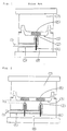
- Fig. 1 shows a longitudinal sectional view of a mold for the press molding of prior art.
- Fig. 2 shows a longitudinal sectional view of a mold for the press molding of the present invention.
- Fig. 2 exemplifies the mold of the present invention, in which the molten resin passage (1) is provided in the lower half, and the tip portion of the nozzle (2) is separated from the mold cavity side surface (3) of the mold by 10-100 mm below (which is indicated by a distance "h" in Fig. 2).
- the same members have the same reference numerals.
- a single nozzle (2) is not necessarily provided per a single passage, and two or more nozzles may be provided per a single passage as desired.
- the nozzle (2) has an opening-closing function for the resin passage and pins (4) are provided in lower portions of the nozzles for the opening and closing operation.
- the pin (4) is raised or lowered by supply or stop of the molten resin by means of a hydraulic apparatus (not shown).
- the pin (4) is lowered when the resin is supplied so that a space is defined between the nozzle (2) and the pin (4) whereby the molten resin passage is in a open position.
- the pin (4) is raised and the tip portion thereof closes an opening of the nozzle (2) so that the molten resin passage is closed.
- the tip portion of the pin (4) should have a shape and a design such that the pin (4) completely closes the opening of the nozzle (2) when the pin (4) is raised and contacts the opening of the nozzle (2).
- the tip portion may be in a semi-spherical form which inscribes or circumscribes the opening of the nozzle, or in a cylindrical form of which diameter is larger than that of the opening of the nozzle.
- the shape and the design may be any suitable ones provided that they achieve their functions.
- a position of the tip portion of the nozzle (2) is located 10-100 mm and preferably 20-80 mm (shown as a distance "h" in Fig. 2) below the cavity side surface (3) of the mold.
- a portion of the resin passage between the nozzle (2) and the cavity side surface may have the same diameter as that of the nozzle, and preferably such a portion of the molten resin passage is so tapered that a diameter of an opening on the cavity side surface is larger a little than the diameter of the nozzle.
- the distance between the tip portion of the nozzle and the cavity side surface is smaller than 10 mm, it is difficult to uniformly keep a temperature on the mold surface and a molded article having a good appearance cannot be produced when a molding cycle is short.
- the distance between the tip portion of the nozzle and the cavity side surface exceeds 100 mm, a thickness of the mold is increased and a weight of the mold is also increased.
- nozzle opening and closing mechanism in place of the mechanism in which the pin (4) for the opening and closing function is provided in the lower portion of the nozzle as described above, various mechanisms may be employed.
- a spring which expands depending on a supply pressure of the resin is provided in the nozzle so that the spring shrinks and the nozzle is in the open position when the resin supplying pressure is applied to the resin in the nozzle by the resin supply, and the spring expands and the nozzle opening is closed when the resin supply is stopped and the resin supplying pressure is not acted.
- mechanism is to be employed. It is preferred to employ a mechanism in which the pin is operated by the hydraulic apparatus from view points that the opening operation and the closing operation are ensured and that when the mold has a plurality of the nozzles, the opening and the closing of each nozzle can be controlled separately.
- the molten resin is supplied at a low pressure to a cavity in the mold which is not completely closed and then or while pressurized so that edge portions of the cavity are filled with the resin and then the shaping is carried out. Therefore, when the mold has a plurality of the nozzles, gate balance greatly affects and thus nozzle arrangement and an amount of the molten resin supplied through each nozzle should be adjusted properly. In addition, when a resin temperature, a mold temperature and its distribution are not proper, a shape of the molded article is adversely affected by them. In order to deal with this problem properly, the opening and the closing of the molten resin passage should be surely carried out in an extremely short period and opening and closing periods of each nozzle should be separately controlled.
- the present mold may comprise a plurality of thin tubes therein through which a heating medium is circulated to keep the mold at a desired temperature.
- the mold may comprise a heater (5) in a periphery of the molten resin passage so as to keep a temperature of the molten resin constant.
- a cavity may be provided around a periphery of the heater in order that heat from the heater does not affect the mold.
- thermoplastic resin in the molten condition is supplied through the resin passage into the space between the upper half and the lower half which is not closed, the nozzle is closed, and the clamping of the mold is carried out so that the molded article having a good appearance is produced.
- the molten resin is supplied during the clearance between the upper half and the lower half is (C+0.1) to 50 mm wherein C is a clearance on final clamping, and during the supply, the clamping is carried out at a rate of not more than 30 mm/sec. or the clamping is temporarily stopped, and then the clamping is re-started at the same time of or just before the completion of the supply of the molten resin.
- the molten resin is supplied during the clearance of the cavity is (C+5) to (C+100) mm in order that the skin material is not damaged by the pressure and the heat.
- thermoplastic material which is used in the present press molding process is any material which is usually used in the injection molding or the extrusion molding.
- a polypropylene, a polyethylene, a polystyrene, an acrylonitrile/butadiene copolymer and a nylon can be used.
- the skin material when used in the present process, it includes a polyvinyl chloride sheet, a thermoplastic elastomer sheet or a leather like sheet thereof of which surface is embossed or a woven fabric, a nonwoven fabric or a fabric of which back side is laminated with an expanded polyethylene sheet, an expanded polypropylene sheet or an expanded polyurethane sheet and so on.
- molding conditions are not specifically limited and the conventional molding conditions are applied.
- the preferred conditions for the production of the molded article having a good appearance include a resin temperature of 200-280 °C and a mold temperature of 50-100 °C and when the skin material is laminated, the preferred conditions include the resin temperature of 170-220 °C and the mold temperature of 20-50 °C
- the mold for the press molding according to the present invention since the mold for the press molding according to the present invention has the nozzle of which tip portion is located the proper distance below the mold surface, the cavity side surface of the mold is hardly affected by the heat from the tip portion of the nozzle. Therefore, when the thermoplastic resin is press molded using the present mold, the molded article having the good appearance can be produced even when the molding cycle is short.
- the lower half (8) as shown in Fig. 2 was used in which the molten resin passage was provided and the tip portions of the two nozzles were separated from the cavity side surface of the mold by a distance of 20 mm.
- a temperature of the upper half was set at 90 °C and a temperature of the lower half was set at 80 °C, respectively.
- a polypropylene available from Sumitomo Chemical Co., Ltd. under a trade name of Sumitomo-Noblen® AX568, having a melt flow index of 65 g/1 0 min.
- the resin was supplied into the lower half and press molded in a following procedure to produce molded articles.
- the molten resin (6) was supplied into the cavity through the molten resin passage by lowering the pin (4) by means of a hydraulic cylinder so that the nozzle (2) was opened, and the pin (4) was raised so that the opening of the nozzle (5) was closed and the resin passage was closed after a desired amount of the resin was supplied whereby the supply of the resin was finished.
- lowering of the upper half (7) was started.
- the lowering of the upper half (7) was temporarily stopped when the cavity clearance became 3 mm, and then the supply of the molten resin (6) was started.
- the lowering of the upper half (7) was restarted so that the molten resin (6) was press-shaped, then the resin was cooled for 40 seconds while the pressure was applied and then the upper half was raised so that the molded article was taken out.
- a thickness of the molded article was 1.8 mm and the molding cycle was 55 seconds. Even when such a molding procedure was repeated 500 times in series, the molded articles were produced which had a good appearance without bulge and defective gloss.
- the upper half is lowered till the cavity clearance between the upper half (7) and the lower half (8) became 50 mm, the lowering rate of the upper half was set at 5 mm/sec. and the molten resin (6) was supplied through two nozzles (2).
- the molten resin was supplied between the skin material and the lower half while it pressed the skin material against the upper half surface.
- the cavity clearance became 20 mm
- the supply of the resin was finished and, at the same time, the pin (4) was raised so that the opening of each nozzle (2) was closed and the resin passage was stopped.
- the upper half (6) was lowered, the molten resin was pressured and the edge portions of the cavity were filled with the fluid resin while the resin pressed the skin material thereon against the upper half.
- the application of the pressure with cooling was kept for 40 seconds and then the upper half was raised so that the intended multi-layer molded article was taken out.
- the cycle of this molding procedure was 65 seconds. Even when such a molding procedure was repeated 100 times in series, the molded multi-layer articles were produced each of which had a good appearance without bulge nor defective gloss.
- Example 1 was repeated except that a mold in which the tip portion of the nozzle (2) was 5 mm below the cavity side surface of the mold was used.
- the articles molded in up to the fifteenth cycle had a good appearance.
- the article molded in the twentieth or more cycle had depressions on portions which were adjacent to the nozzles, and the article molded in the thirtieth or more cycle had remarkable deformations.
- the tip portion of the nozzle is separated from the cavity side surface of the mold by the proper distance in the mold for the press molding according to the present invention, the cavity side surface of the mold is hardly affected by the heat from the nozzle.
- the press molding of the thermoplastic resin is carried out using the mold, the molded article having the good appearance can be produced even when the molding cycle is short.
Landscapes
- Engineering & Computer Science (AREA)
- Mechanical Engineering (AREA)
- Manufacturing & Machinery (AREA)
- Casting Or Compression Moulding Of Plastics Or The Like (AREA)
Applications Claiming Priority (3)
| Application Number | Priority Date | Filing Date | Title |
|---|---|---|---|
| JP94265/91 | 1991-04-24 | ||
| JP9426591 | 1991-04-24 | ||
| PCT/JP1992/000525 WO1992019433A1 (fr) | 1991-04-24 | 1992-04-23 | Matrice et procede de matriçage par pression de resine thermoplastique a l'aide de cette matrice |
Publications (3)
| Publication Number | Publication Date |
|---|---|
| EP0537367A1 true EP0537367A1 (de) | 1993-04-21 |
| EP0537367A4 EP0537367A4 (en) | 1993-09-08 |
| EP0537367B1 EP0537367B1 (de) | 1997-07-09 |
Family
ID=14105453
Family Applications (1)
| Application Number | Title | Priority Date | Filing Date |
|---|---|---|---|
| EP92909479A Expired - Lifetime EP0537367B1 (de) | 1991-04-24 | 1992-04-23 | Pressform und verfahren zum pressformen von thermoplastischen harzen unter verwendung dieser pressform |
Country Status (7)
| Country | Link |
|---|---|
| US (1) | US5336463A (de) |
| EP (1) | EP0537367B1 (de) |
| KR (1) | KR100200026B1 (de) |
| CA (1) | CA2086106C (de) |
| DE (1) | DE69220750T2 (de) |
| ES (1) | ES2104913T3 (de) |
| WO (1) | WO1992019433A1 (de) |
Families Citing this family (10)
| Publication number | Priority date | Publication date | Assignee | Title |
|---|---|---|---|---|
| EP0623435A1 (de) * | 1993-04-30 | 1994-11-09 | Sumitomo Chemical Company, Limited | Verfahren zur Herstellung einer Form für Beton aus thermoplastischem Kunststoff |
| US5437823A (en) * | 1993-06-23 | 1995-08-01 | Hettinga; Siebolt | Method for molding a plastic article of varied density |
| JP3358277B2 (ja) | 1994-03-28 | 2002-12-16 | 住友化学工業株式会社 | 多層成形体の製造方法 |
| JPH08118387A (ja) * | 1994-09-01 | 1996-05-14 | Sumitomo Chem Co Ltd | 熱可塑性樹脂成形体の製造方法 |
| EP0765722A1 (de) * | 1995-09-28 | 1997-04-02 | Siebolt Hettinga | Verfahren zum Kontrollieren der Dicke der Haut eines Kunststoffgegenstandes mit regelter Dichte |
| US6423167B1 (en) | 1998-06-05 | 2002-07-23 | Premark Rwp Holdings | Method for controlling laminate gloss |
| US6632507B2 (en) | 1998-06-05 | 2003-10-14 | Premark Rwp Holdings, Inc. | Holographically enhanced decorative laminate |
| CA2351424A1 (en) * | 1998-11-20 | 2000-06-02 | Krauss-Maffei Kunststofftechnik Gmbh | Method of producing injection-molded parts in an injection-molding machine |
| US7045206B1 (en) | 2000-07-10 | 2006-05-16 | Visteon Global Technologies, Inc. | Molded panels having a soft pad armrest |
| US7281917B2 (en) * | 2004-12-01 | 2007-10-16 | Patwin Plastics, Inc. | Extrusion/reaction injection molding system |
Family Cites Families (8)
| Publication number | Priority date | Publication date | Assignee | Title |
|---|---|---|---|---|
| FR2545033B1 (fr) * | 1983-04-28 | 1985-08-16 | Cibie Projecteurs | Procede et dispositif pour la realisation de pieces en matiere plastique, sur presse a injection |
| JPS6031930A (ja) * | 1983-07-29 | 1985-02-18 | Sumitomo Chem Co Ltd | 熱可塑性樹脂のプレス成形方法 |
| JPH0615183B2 (ja) * | 1984-07-10 | 1994-03-02 | 住友化学工業株式会社 | 熱可塑性樹脂のプレス成形方法 |
| JPH01235613A (ja) * | 1988-03-16 | 1989-09-20 | Sumitomo Chem Co Ltd | 多層成形品の製造方法 |
| JPH0292514A (ja) * | 1988-09-29 | 1990-04-03 | Komatsu Ltd | 射出プレス複合成形機の射出装置の支持装置 |
| KR0145519B1 (ko) * | 1988-10-27 | 1998-07-15 | 가다다 데츠야 | 사출압축성형장치 및 그의 성형방법 |
| JPH069813Y2 (ja) * | 1989-06-14 | 1994-03-16 | 株式会社細川製作所 | 溶融樹脂加圧成型装置における溶融樹脂供給装置 |
| JPH0371816A (ja) * | 1989-08-11 | 1991-03-27 | Komatsu Ltd | 射出プレス複合成形機のノズルタッチ機構 |
-
1992
- 1992-04-23 WO PCT/JP1992/000525 patent/WO1992019433A1/ja not_active Ceased
- 1992-04-23 EP EP92909479A patent/EP0537367B1/de not_active Expired - Lifetime
- 1992-04-23 ES ES92909479T patent/ES2104913T3/es not_active Expired - Lifetime
- 1992-04-23 DE DE69220750T patent/DE69220750T2/de not_active Expired - Lifetime
- 1992-04-23 CA CA002086106A patent/CA2086106C/en not_active Expired - Lifetime
- 1992-12-24 KR KR1019920703342A patent/KR100200026B1/ko not_active Expired - Lifetime
- 1992-12-24 US US07/955,756 patent/US5336463A/en not_active Expired - Lifetime
Also Published As
| Publication number | Publication date |
|---|---|
| DE69220750T2 (de) | 1997-11-06 |
| CA2086106A1 (en) | 1992-10-25 |
| DE69220750D1 (de) | 1997-08-14 |
| WO1992019433A1 (fr) | 1992-11-12 |
| EP0537367B1 (de) | 1997-07-09 |
| CA2086106C (en) | 2002-05-21 |
| EP0537367A4 (en) | 1993-09-08 |
| KR100200026B1 (ko) | 1999-06-15 |
| KR930701279A (ko) | 1993-06-11 |
| US5336463A (en) | 1994-08-09 |
| ES2104913T3 (es) | 1997-10-16 |
Similar Documents
| Publication | Publication Date | Title |
|---|---|---|
| CA1334613C (en) | Process for producing a multilayer molded article | |
| JP2942771B2 (ja) | 深絞りによるプラスチック成形法 | |
| KR100217975B1 (ko) | 다층 성형품의 제조방법 | |
| US5441675A (en) | Forming method and apparatus | |
| KR20030015155A (ko) | 성형된 표면조직으로 부품을 성형하는 방법 및 기구 | |
| US6030573A (en) | Process for manufacturing thermoplastic resin moldings | |
| EP0498444B1 (de) | Verfahren zur Herstellung eines geformten Hohlkörpers | |
| US20030001310A1 (en) | Hybrid injection molding process for enhancing exterior appearance of molded articles by molding fabric thereto | |
| EP0477967A2 (de) | Verfahren zum Pressformen von thermoplastischen Harzen | |
| EP0537367B1 (de) | Pressform und verfahren zum pressformen von thermoplastischen harzen unter verwendung dieser pressform | |
| CN1321796C (zh) | 吹塑成形方法、吹塑成形制品及吹塑成形金属模 | |
| US5795526A (en) | Process for producing multilayer molded article | |
| EP0466181B1 (de) | Verfahren zur Herstellung eines Formkörpers aus thermoplastischem Kunstharz | |
| JPS63249616A (ja) | 樹脂成形方法 | |
| GB2182601A (en) | Moulding expanded resin cups | |
| US6183680B1 (en) | Process for producing multilayer molded article | |
| CN1035753C (zh) | 塑料片材的热成型方法及其装置 | |
| JP2743689B2 (ja) | プレス成形用金型およびこれを用いてなる熱可塑性樹脂のプレス成形方法 | |
| EP0549809A1 (de) | Verfahren zur herstellung laminierter formteile | |
| EP0654336B1 (de) | Formverfahren zum herstellen von mehrschicht-gegenständen | |
| US5207969A (en) | Process of producing blow molded article | |
| JPH07299841A (ja) | 複層成形体の成形方法 | |
| JPH0880532A (ja) | 成形用金型およびそれを用いる多層成形品の製造法 | |
| JP3378333B2 (ja) | 多層成形品の製造方法 | |
| JP2000108131A (ja) | 加飾成形品の製造方法および加飾成形用金型 |
Legal Events
| Date | Code | Title | Description |
|---|---|---|---|
| PUAI | Public reference made under article 153(3) epc to a published international application that has entered the european phase |
Free format text: ORIGINAL CODE: 0009012 |
|
| 17P | Request for examination filed |
Effective date: 19930120 |
|
| AK | Designated contracting states |
Kind code of ref document: A1 Designated state(s): BE DE ES FR GB IT NL |
|
| A4 | Supplementary search report drawn up and despatched |
Effective date: 19930726 |
|
| AK | Designated contracting states |
Kind code of ref document: A4 Designated state(s): BE DE ES FR GB IT NL |
|
| 17Q | First examination report despatched |
Effective date: 19950123 |
|
| GRAG | Despatch of communication of intention to grant |
Free format text: ORIGINAL CODE: EPIDOS AGRA |
|
| GRAH | Despatch of communication of intention to grant a patent |
Free format text: ORIGINAL CODE: EPIDOS IGRA |
|
| GRAH | Despatch of communication of intention to grant a patent |
Free format text: ORIGINAL CODE: EPIDOS IGRA |
|
| GRAA | (expected) grant |
Free format text: ORIGINAL CODE: 0009210 |
|
| AK | Designated contracting states |
Kind code of ref document: B1 Designated state(s): BE DE ES FR GB IT NL |
|
| REF | Corresponds to: |
Ref document number: 69220750 Country of ref document: DE Date of ref document: 19970814 |
|
| REG | Reference to a national code |
Ref country code: ES Ref legal event code: FG2A Ref document number: 2104913 Country of ref document: ES Kind code of ref document: T3 |
|
| ET | Fr: translation filed | ||
| PLBE | No opposition filed within time limit |
Free format text: ORIGINAL CODE: 0009261 |
|
| 26N | No opposition filed | ||
| REG | Reference to a national code |
Ref country code: GB Ref legal event code: IF02 |
|
| PGFP | Annual fee paid to national office [announced via postgrant information from national office to epo] |
Ref country code: FR Payment date: 20110426 Year of fee payment: 20 Ref country code: ES Payment date: 20110518 Year of fee payment: 20 Ref country code: DE Payment date: 20110420 Year of fee payment: 20 |
|
| PGFP | Annual fee paid to national office [announced via postgrant information from national office to epo] |
Ref country code: NL Payment date: 20110420 Year of fee payment: 20 Ref country code: BE Payment date: 20110411 Year of fee payment: 20 Ref country code: GB Payment date: 20110420 Year of fee payment: 20 |
|
| PGFP | Annual fee paid to national office [announced via postgrant information from national office to epo] |
Ref country code: IT Payment date: 20110421 Year of fee payment: 20 |
|
| REG | Reference to a national code |
Ref country code: DE Ref legal event code: R071 Ref document number: 69220750 Country of ref document: DE |
|
| REG | Reference to a national code |
Ref country code: DE Ref legal event code: R071 Ref document number: 69220750 Country of ref document: DE |
|
| BE20 | Be: patent expired |
Owner name: *SUMITOMO CHEMICAL CY LTD Effective date: 20120423 |
|
| REG | Reference to a national code |
Ref country code: NL Ref legal event code: V4 Effective date: 20120423 |
|
| REG | Reference to a national code |
Ref country code: GB Ref legal event code: PE20 Expiry date: 20120422 |
|
| PG25 | Lapsed in a contracting state [announced via postgrant information from national office to epo] |
Ref country code: DE Free format text: LAPSE BECAUSE OF EXPIRATION OF PROTECTION Effective date: 20120424 |
|
| PG25 | Lapsed in a contracting state [announced via postgrant information from national office to epo] |
Ref country code: GB Free format text: LAPSE BECAUSE OF EXPIRATION OF PROTECTION Effective date: 20120422 |
|
| REG | Reference to a national code |
Ref country code: ES Ref legal event code: FD2A Effective date: 20130718 |
|
| PG25 | Lapsed in a contracting state [announced via postgrant information from national office to epo] |
Ref country code: ES Free format text: LAPSE BECAUSE OF EXPIRATION OF PROTECTION Effective date: 20120424 |