EP0537496A1 - Méthode pour cintrer des bouts de barres pour la construction civile avec des cintreuses coupantes, et cintreuses coupantes utilisant la méthode - Google Patents
Méthode pour cintrer des bouts de barres pour la construction civile avec des cintreuses coupantes, et cintreuses coupantes utilisant la méthode Download PDFInfo
- Publication number
- EP0537496A1 EP0537496A1 EP92116005A EP92116005A EP0537496A1 EP 0537496 A1 EP0537496 A1 EP 0537496A1 EP 92116005 A EP92116005 A EP 92116005A EP 92116005 A EP92116005 A EP 92116005A EP 0537496 A1 EP0537496 A1 EP 0537496A1
- Authority
- EP
- European Patent Office
- Prior art keywords
- bending
- bar
- assembly
- bars
- building work
- Prior art date
- Legal status (The legal status is an assumption and is not a legal conclusion. Google has not performed a legal analysis and makes no representation as to the accuracy of the status listed.)
- Withdrawn
Links
Images

Classifications
-
- B—PERFORMING OPERATIONS; TRANSPORTING
- B21—MECHANICAL METAL-WORKING WITHOUT ESSENTIALLY REMOVING MATERIAL; PUNCHING METAL
- B21D—WORKING OR PROCESSING OF SHEET METAL OR METAL TUBES, RODS OR PROFILES WITHOUT ESSENTIALLY REMOVING MATERIAL; PUNCHING METAL
- B21D11/00—Bending not restricted to forms of material mentioned in only one of groups B21D5/00, B21D7/00, B21D9/00; Bending not provided for in groups B21D5/00 - B21D9/00; Twisting
- B21D11/10—Bending specially adapted to produce specific articles, e.g. leaf springs
- B21D11/12—Bending specially adapted to produce specific articles, e.g. leaf springs the articles being reinforcements for concrete
-
- B—PERFORMING OPERATIONS; TRANSPORTING
- B21—MECHANICAL METAL-WORKING WITHOUT ESSENTIALLY REMOVING MATERIAL; PUNCHING METAL
- B21D—WORKING OR PROCESSING OF SHEET METAL OR METAL TUBES, RODS OR PROFILES WITHOUT ESSENTIALLY REMOVING MATERIAL; PUNCHING METAL
- B21D7/00—Bending rods, profiles, or tubes
Definitions
- This invention concerns a method to make bends in the trailing ends of bars for building work in bending-shaping machines and concerns also bending-shaping machines for bars for building work which employ such method, as set forth in the relative main claims.
- the method of this invention to make bends in the trailing ends is applied properly to the field of processing sections for reinforcements in reinforced concrete, the sections being in the form of bars or rolls of a round, square, polygonal or other cross section.
- the bending-shaping machines of the state of the art which are characterized by having one single bending assembly downstream of a shearing assembly and of a straightening-drawing assembly, or a drawing assembly alone, entail the problem of making bends in the trailing end of the bar.
- Document IT-B-1024229 discloses a teaching of making the bend in the trailing end, lowering the bending assembly and bringing the section back to the required length before performing the shearing. This system entails long processing times and lowering and raising mechanisms which by their use involve great consumptions of energy and problems of wear and maintenance.
- Document IT 83349 A/89 discloses a proposal to arrange the shears assembly separately above the bending assembly, but this proposal entails the problem of shearing the trailing end where the trailing end is long.
- Documents IT 83543 A/90 and EP-A-0.379.043 disclose a bending-shaping machine which comprises a retractable drawing assembly located downstream of the bending assembly.
- This retractable drawing assembly enables the section to be clamped and, after the shearing operation, to be drawn downstream by a desired length so that the bend in the trailing end can then be made.
- This teaching is in itself interesting and useful but involves problems of overall bulk and of moving the drawing assembly, with resulting problems of wasted energy, maintenance, wasted materials and a complex structure.
- Document DE-A-1.249.057 teaches a complex system for expanding the abutment roll for as to clamp the bar. This system cannot be applied to bending/shaping machines which produce up to 1500/1600 stirrups an hour because it has a very short life and is complex to handle.
- Document DE-A-1.920.668 teaches the thrusting of a bar with an appropriate jack, but this teaching cannot be applied to bending/shaping machines owing to the high working speed, the need for simplicity and the necessity of not having any contacts during the travel of the bar.
- EP-A-0.371.960 teaches the use of the bending pin of an end-bending assembly to clamp the bar while the other bending assemblies are positioned.
- the invention consists in providing a normal bending-shaping machine for bars for building work and also a method which enables bends to be made in the trailing end of bars for building work, even when the end segment of the bent bar has a length different from the distance between the shearing plane and the axis of the abutment roll of the bending assembly.
- a first formulation of the method to make bends in the trailing end of bars according to the invention provides that, after all the bends have been made except the bend in the trailing end and after shearing to size has taken place and has separated the bent bar from the feeding section, the bar is thrust downstream by the distance required by the feeding action of the feeding section.
- the feeding section When the feeding section has thrust the bent bar downstream by the distance required, the feeding section moves back to its starting position and the bend is made in the trailing end of the bar.
- This first formulation includes clamping means or abutment means or other means suitable for the purpose which are positioned downstream of the bending assembly so as to hold the bar rigidly in position during the aforesaid step of making the bend in the trailing end of the bar.
- clamping means or abutment means or other means suitable for the purpose can be retracted below the working plane so as to enable the preceding bends to be made in the bar.
- a second formulation of the method to make bends in the trailing end of the bar according to the invention provides that the bending assembly can move parallel to the axis of feed of the bar.
- This motion of feed is achieved, for instance, by slider means able to move on suitable guides, the bending assembly being positioned on these slider means.
- the bending assembly is rotated by an amount enough to clamp the bar by bending the same, and the bar will abut against a third retractable point; the bending assembly is then moved forwards downstream until it has displaced the bent bar by the required distance.
- the bending assembly then releases the bent bar, which is clamped by an appropriate retractable assembly and is brought back upstream by a required value, at which the bend in the trailing end of the bar is made.
- Figs.1 show a cycle of making a bend in the trailing end of a bar according to a first formulation of the method of this invention.
- Fig.1a shows a bar 10 coming in this example from a wound roll, the bar 10 having undergone all the bending operations except that of its trailing end; for the sake of simplicity the bends made consist here of one single bend 23, which in this case is a hook in the leading end of the bar 10.
- the displacements of the bar 10 along the working plane are brought about by a drawing assembly 11 located upstream of a bending assembly 12.
- the drawing assembly 11 may comprise also a straightening assembly or may consist of a straightening assembly alone.
- the drawing assembly 11 and bending assembly 12 form part of the state of the art and are therefore unimportant for the purposes of the invention.
- the bending assembly 12 comprises a bending disk 13, a bending pin 14 and an abutment roll 15.
- the rod 10 is sheared to the desired length by a shearing assembly 16 and thus is separated from a feeding section 22.
- the sheared bar 10 is thrust downstream by the feeding section 22, which is drawn forwards by the desired length and cooperates by butting against the bar 10 (Fig.1b).
- the feeding section 22 is moved backwards and the bending assembly 12 makes the bend in the trailing end 24,in this case a lefthand bend (Fig.1c); this bend 24 in the trailing end can be of any type.
- clamping means 17 are positioned downstream of the bending unit 12 and consist, in this case, of two idler rolls 18 capable of a movement orthogonal to the working plane in this example.
- clamping means 17 are retractable so as to enable the preceding bends 23 to be made without the bar 10 coming into contact with the clamping means 17.
- the clamping means 17 may also consist of a vice or, where they consist of rolls, may be capable also of rotary movement.
- Fig.1a the clamping means 17 are located below the working plane, whereas in Fig.1b the clamping means 17 position the bar 10 and let it slide, while in Fig.1c the clamping means 17 grip the bar 10 and keep it in position during the performance of the bend 24 in the trailing end.
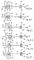
- Figs.2 show a cycle of making a bend in the trailing end according to the second formulation of the method of this invention.
- Fig.2a shows a rod 10 coming, in this case, from a wound roll of a feeding section 22 and having all the bends 23, except bends 24 in the trailing end, already made; these bends 23 already made are summarized in this case with one single hook. With all these bends 23 made, the bar 10 is sheared to the desired length by the shearing assembly 16 (Fig.2a).
- the bending assembly 12 is positioned on a suitable slider 19 which can move on guides 21 parallel to the axis of feed of the bar 10.
- the bending assembly 12 After making the bends 23, but not bends in the trailing end, and after the bar 10 has been sheared to the desired length, the bending assembly 12 is rotated about its axis until the bending pin 14 rests against the bar 10 and compels the bar 10 to rest against a clamping means 117, so that the bar 10 is clamped between the bending pin 14 and the abutment roll 15 (Fig.2b).
- clamping means 117 are retractable and consist of two idler rolls 20 capable, in this example, of a movement orthogonal to the working plane.
- the bending assembly 12 (Fig.2c) is moved downstream by the desired distance and takes the bar 10 with it.
- the bending assembly 12 retreats to its bending position (Fig.2e), where it makes the bend 24 in the trailing end with the desired bending angle (Fig.2f).
- the bending assembly 12 may be of any type and may carry out any other known auxiliary movement.
Landscapes
- Engineering & Computer Science (AREA)
- Mechanical Engineering (AREA)
- Bending Of Plates, Rods, And Pipes (AREA)
- Wire Processing (AREA)
Applications Claiming Priority (2)
| Application Number | Priority Date | Filing Date | Title |
|---|---|---|---|
| ITUD910169 | 1991-10-15 | ||
| ITUD910169A IT1252962B (it) | 1991-10-15 | 1991-10-15 | Procedimento per l'esecuzione delle pieghe di coda nei ferri per l'edilizia in macchine piegatrici/ sagomatrici e macchine piegatrici/ sagomatrici per ferri per l'edilizia adottanti tale procedimento |
Publications (1)
| Publication Number | Publication Date |
|---|---|
| EP0537496A1 true EP0537496A1 (fr) | 1993-04-21 |
Family
ID=11420927
Family Applications (1)
| Application Number | Title | Priority Date | Filing Date |
|---|---|---|---|
| EP92116005A Withdrawn EP0537496A1 (fr) | 1991-10-15 | 1992-09-18 | Méthode pour cintrer des bouts de barres pour la construction civile avec des cintreuses coupantes, et cintreuses coupantes utilisant la méthode |
Country Status (4)
| Country | Link |
|---|---|
| EP (1) | EP0537496A1 (fr) |
| KR (1) | KR930007531A (fr) |
| CA (1) | CA2080032A1 (fr) |
| IT (1) | IT1252962B (fr) |
Cited By (10)
| Publication number | Priority date | Publication date | Assignee | Title |
|---|---|---|---|---|
| EP0875309A1 (fr) * | 1997-04-29 | 1998-11-04 | M.E.P. Macchine Elettroniche Piegatrici S.p.A. | Système de pliage preferentiel pour machine à plier |
| WO2003024640A1 (fr) * | 2001-09-14 | 2003-03-27 | M.E.P. Macchine Elettroniche Piegatrici Spa | Cintreuse pour profiles, tels que des pieces rondes de renforcement ou similaires |
| WO2003045603A1 (fr) * | 2001-11-30 | 2003-06-05 | M.E.P. Macchine Elettroniche Piegatrici Spa | Machine a plier conçue pour des profiles tels que des pieces circulaires de renfort ou des pieces analogues |
| EP1247594A3 (fr) * | 2001-04-06 | 2003-07-16 | Schnell S.p.A. | Procédé de pliage de barres profilées et dispositif pour la réalisation dudit procédé |
| EP1247595A3 (fr) * | 2001-04-06 | 2003-07-16 | Schnell S.p.A. | Procédé de pliage de barres profilées et dispositif pour la réalisation dudit procédé |
| EP1396296A1 (fr) * | 2002-09-04 | 2004-03-10 | Schnell S.p.A. | Procédé pour couper et éventuellement plier des profilés par une plieuse et une machine de formage, notamment des profilés en forme de barres |
| US7610788B2 (en) | 2005-11-15 | 2009-11-03 | Antonios Anagnostopoulos | Machine and method for preventing torsion of wire, material of prismatic cross-section, and rod material |
| CN105013986A (zh) * | 2015-05-27 | 2015-11-04 | 德清铭泰户外用品有限公司 | 一种钢丝自动弯折裁剪设备 |
| CN105195651A (zh) * | 2015-10-29 | 2015-12-30 | 胡满航 | 地脚螺栓的新型成型方法 |
| CN105414400A (zh) * | 2015-10-29 | 2016-03-23 | 胡满航 | 一种地脚螺栓生产线 |
Citations (5)
| Publication number | Priority date | Publication date | Assignee | Title |
|---|---|---|---|---|
| DE1249057B (de) * | 1967-08-31 | Fa Paul Ferd Peddmghaus Gevelsberg (Westf) | Mitnehmer fur Formstucke fur Betonstahlbiegemaschinen | |
| DE1920668A1 (de) * | 1968-04-23 | 1969-11-13 | Pines Engineering Co Inc | Numerisch gesteuerte Rohrbiegemaschine |
| FR2290969A1 (fr) * | 1974-11-15 | 1976-06-11 | Fabro Remigio Del | Machine automatique pour fabriquer des etriers |
| EP0371960A2 (fr) * | 1986-03-14 | 1990-06-06 | Ruhl, Heinz | Procédé pour cintrer des matériaux en forme de barre |
| EP0379043A1 (fr) * | 1989-01-18 | 1990-07-25 | M.E.P. Macchine Elettroniche Piegatrici S.p.A. | Dispositif de traînage monté en aval d'une cintreuse et procédé pour cintrer les bouts arrières de barres |
-
1991
- 1991-10-15 IT ITUD910169A patent/IT1252962B/it active IP Right Grant
-
1992
- 1992-09-18 EP EP92116005A patent/EP0537496A1/fr not_active Withdrawn
- 1992-10-07 CA CA002080032A patent/CA2080032A1/fr not_active Abandoned
- 1992-10-08 KR KR1019920018446A patent/KR930007531A/ko not_active Withdrawn
Patent Citations (5)
| Publication number | Priority date | Publication date | Assignee | Title |
|---|---|---|---|---|
| DE1249057B (de) * | 1967-08-31 | Fa Paul Ferd Peddmghaus Gevelsberg (Westf) | Mitnehmer fur Formstucke fur Betonstahlbiegemaschinen | |
| DE1920668A1 (de) * | 1968-04-23 | 1969-11-13 | Pines Engineering Co Inc | Numerisch gesteuerte Rohrbiegemaschine |
| FR2290969A1 (fr) * | 1974-11-15 | 1976-06-11 | Fabro Remigio Del | Machine automatique pour fabriquer des etriers |
| EP0371960A2 (fr) * | 1986-03-14 | 1990-06-06 | Ruhl, Heinz | Procédé pour cintrer des matériaux en forme de barre |
| EP0379043A1 (fr) * | 1989-01-18 | 1990-07-25 | M.E.P. Macchine Elettroniche Piegatrici S.p.A. | Dispositif de traînage monté en aval d'une cintreuse et procédé pour cintrer les bouts arrières de barres |
Cited By (13)
| Publication number | Priority date | Publication date | Assignee | Title |
|---|---|---|---|---|
| US5966979A (en) * | 1997-04-29 | 1999-10-19 | M.E.P. Macchine Elettroniche Piegatrici Spa | Bending machine and method having positionable drawing rolls and limiting mechanism defining a transit and containing space for the workpiece |
| EP0875309A1 (fr) * | 1997-04-29 | 1998-11-04 | M.E.P. Macchine Elettroniche Piegatrici S.p.A. | Système de pliage preferentiel pour machine à plier |
| EP1247594A3 (fr) * | 2001-04-06 | 2003-07-16 | Schnell S.p.A. | Procédé de pliage de barres profilées et dispositif pour la réalisation dudit procédé |
| EP1247595A3 (fr) * | 2001-04-06 | 2003-07-16 | Schnell S.p.A. | Procédé de pliage de barres profilées et dispositif pour la réalisation dudit procédé |
| WO2003024640A1 (fr) * | 2001-09-14 | 2003-03-27 | M.E.P. Macchine Elettroniche Piegatrici Spa | Cintreuse pour profiles, tels que des pieces rondes de renforcement ou similaires |
| US7004003B2 (en) | 2001-09-14 | 2006-02-28 | M.E.P. Macchine Elettroniche Piegatrici Spa | Bending machine for profiles |
| US7104102B2 (en) | 2001-11-30 | 2006-09-12 | M.E.P. Macchine Elettroniche Piegatrici Spa | Bending machine for profiles such as reinforcement round pieces or similar |
| WO2003045603A1 (fr) * | 2001-11-30 | 2003-06-05 | M.E.P. Macchine Elettroniche Piegatrici Spa | Machine a plier conçue pour des profiles tels que des pieces circulaires de renfort ou des pieces analogues |
| EP1396296A1 (fr) * | 2002-09-04 | 2004-03-10 | Schnell S.p.A. | Procédé pour couper et éventuellement plier des profilés par une plieuse et une machine de formage, notamment des profilés en forme de barres |
| US7610788B2 (en) | 2005-11-15 | 2009-11-03 | Antonios Anagnostopoulos | Machine and method for preventing torsion of wire, material of prismatic cross-section, and rod material |
| CN105013986A (zh) * | 2015-05-27 | 2015-11-04 | 德清铭泰户外用品有限公司 | 一种钢丝自动弯折裁剪设备 |
| CN105195651A (zh) * | 2015-10-29 | 2015-12-30 | 胡满航 | 地脚螺栓的新型成型方法 |
| CN105414400A (zh) * | 2015-10-29 | 2016-03-23 | 胡满航 | 一种地脚螺栓生产线 |
Also Published As
| Publication number | Publication date |
|---|---|
| CA2080032A1 (fr) | 1993-04-16 |
| ITUD910169A0 (it) | 1991-10-15 |
| IT1252962B (it) | 1995-07-07 |
| ITUD910169A1 (it) | 1993-04-15 |
| KR930007531A (ko) | 1993-05-20 |
Similar Documents
| Publication | Publication Date | Title |
|---|---|---|
| EP0379043B1 (fr) | Dispositif de traînage monté en aval d'une cintreuse et procédé pour cintrer les bouts arrières de barres | |
| CA2007985C (fr) | Methode de pliage de l'extremite des barres longitudinales et cisailles mobiles en amont de la plieuse | |
| EP0491195A1 (fr) | Machine de formage par pliage de barres et procédé pour réaliser des courbes aux bouts arrières de barres | |
| US3706331A (en) | Metallic cage structure and apparatus for manufacturing same | |
| US5285671A (en) | Bending-shaping machine having multiple working levels | |
| JP3345436B2 (ja) | 建築作業用の鉄筋を選び、曲げるためのプラント | |
| CN108580739B (zh) | 一种钢筋调直箍筋机 | |
| DE2553152B2 (de) | Biegemaschine fuer stabfoermiges material, insbesondere fuer betonbewehrungsstaebe | |
| CA2080032A1 (fr) | Methode de cintrage de barres utilisees en construction et cintreuses utilisees a ces fins | |
| US5099669A (en) | Bending assembly with satellite | |
| DE10359465B4 (de) | Biegeverarbeitungsvorrichtung für Rohre | |
| CN104259341B (zh) | 一种用于钢筋加工的定向调直裁断弯曲多用机 | |
| KR20200063138A (ko) | 바, 로드, 섹션 바 또는 그러한 것과 같은 바람직하게는 금속인 길쭉한 요소들을 구부리기 위한 기계 및 방법 | |
| US4020669A (en) | Machine for bending bar or rod material | |
| US7260969B2 (en) | Bending machine for profiles and relative bending method | |
| CN205324555U (zh) | 一种线材自动分段剪弯成型机 | |
| EP1711285B1 (fr) | Procede et outil pour le cintrage de materiau en barre | |
| EP0297312A1 (fr) | Machine de forgeage universelle | |
| EP0536167B1 (fr) | Machines a plier | |
| EP0509232A1 (fr) | Unité d'alignement et d'étirage en aval d'une bobine | |
| JPH0241371B2 (fr) | ||
| SU1722670A1 (ru) | Стан поперечно-клиновой прокатки | |
| EP1407839B1 (fr) | Installation pour couper des barres métalliques | |
| EP0427038A1 (fr) | Dispositif de pliage de barres avec butée pour positionner longitudinalement les barres | |
| JPS645971B2 (fr) |
Legal Events
| Date | Code | Title | Description |
|---|---|---|---|
| PUAI | Public reference made under article 153(3) epc to a published international application that has entered the european phase |
Free format text: ORIGINAL CODE: 0009012 |
|
| AK | Designated contracting states |
Kind code of ref document: A1 Designated state(s): AT BE CH DE DK ES FR GB GR IE IT LI LU MC NL PT SE |
|
| 18D | Application deemed to be withdrawn |
Effective date: 19931022 |