EP0875309A1 - Système de pliage preferentiel pour machine à plier - Google Patents
Système de pliage preferentiel pour machine à plier Download PDFInfo
- Publication number
- EP0875309A1 EP0875309A1 EP98106221A EP98106221A EP0875309A1 EP 0875309 A1 EP0875309 A1 EP 0875309A1 EP 98106221 A EP98106221 A EP 98106221A EP 98106221 A EP98106221 A EP 98106221A EP 0875309 A1 EP0875309 A1 EP 0875309A1
- Authority
- EP
- European Patent Office
- Prior art keywords
- bending
- round piece
- limiting element
- working plane
- assembly
- Prior art date
- Legal status (The legal status is an assumption and is not a legal conclusion. Google has not performed a legal analysis and makes no representation as to the accuracy of the status listed.)
- Granted
Links
Images
Classifications
-
- B—PERFORMING OPERATIONS; TRANSPORTING
- B21—MECHANICAL METAL-WORKING WITHOUT ESSENTIALLY REMOVING MATERIAL; PUNCHING METAL
- B21D—WORKING OR PROCESSING OF SHEET METAL OR METAL TUBES, RODS OR PROFILES WITHOUT ESSENTIALLY REMOVING MATERIAL; PUNCHING METAL
- B21D11/00—Bending not restricted to forms of material mentioned in only one of groups B21D5/00, B21D7/00, B21D9/00; Bending not provided for in groups B21D5/00 - B21D9/00; Twisting
- B21D11/10—Bending specially adapted to produce specific articles, e.g. leaf springs
- B21D11/12—Bending specially adapted to produce specific articles, e.g. leaf springs the articles being reinforcements for concrete
Definitions
- This invention concerns a perfected bending system for bending machines as set forth in the main claim.
- the system is applied in machines used for the bending and shaping of metal shapes, particularly, but not only, of round pieces used for reinforcement purposes in constructions of reinforced concrete.
- the invention is applied in bending and/or shaping machines with a horizontal or substantially horizontal working plane.
- section of the metal bar may be of various types, such as three-lobed, square, hexagonal, oval, etc.
- the state of the art covers bending machines for round pieces for reinforcement purposes comprising at least a drawing assembly associated with at least a bending assembly and with a shearing assembly used to make brackets and/or bars shaped according to pre-defined angular or polygonal geometries.
- the drawing assembly normally comprises at least a drawing device consisting of one or more pairs of counter rotating rolls aligned on a perpendicular axis with respect to the longitudinal axis of the round piece in transit.
- the drawing assembly normally also comprises straightening means placed upstream, downstream or both upstream and downstream of the drawing device.
- the round piece In such bending machines, the round piece is often subject to rotations and lengthwise torsions along its axis which may cause considerable problems in the subsequent bending step.
- This tendency to rotate and/or twist on its on axis derives from many factors such as rolling, winding, unwinding, pressure of the drawing rolls, etc.
- the bends already made tend to become detached and rise up with respect to the working plane of the machine as the round piece, as it is fed forwards in order to make the subsequent bends, gradually tends to twist and rotate on its axis.
- the state of the art includes CH-A-336349 which describes a device to form stirrups for reinforcement purposes; the device comprises in sequence a straightening device consisting of two series of rollers orthogonal to each other, a drawing device including rollers which feeds step-by step the wire which is to be bent, a shears, two bending assemblies and a device to discharge the stirrups when they are formed.
- the drawing device is located upstream of the bending assemblies and is associated with a cam mechanism. Therefore, during the feed step, the rollers press on the wire to be drawn with great pressure (Fig. 3) whereas, during the bending step, they are only in contact with the wire (Fig. 5).
- the drawing device is upstream of both the bending assemblies, and since the rollers are arranged in contact with the wire during the bending step, the wire itself is not able to rotate and fall on the working plane if an angular modification of its position occurs as the bending operations proceed.
- the purpose of the invention is to provide a perfected bending system, to be applied to bending machines for round pieces, advantageously but not only round pieces for reinforcement purposes, and to other types of bending machines, which will allow the twisting movements made by the round piece to be recovered and so that all the bends lie substantially on the same plane.
- a further purpose of the invention is to provide a system which will allow shaped brackets and bars of high quality to be made, characterised by great planarity, without modifying substantially the basic structure of the bending machine.
- the bending system according to the invention uses a bending machine of a substantially conventional type comprising a drawing device, consisting of one or more pairs of rolls, cooperating with at least a bending assembly and a mating shearing assembly.
- the drawing device is arranged at an intermediate position between the two bending assemblies.
- the bending machine downstream of the bending assembly and substantially on the same axis as the axis of feed of the round piece, has an element to limit the lift of the front part of the round piece which has already been bent.
- the limiting element is arranged above the plane on which the round piece lies as it passes, and defines between itself and the working plane of the machine a vertical transit space which is little more than the size of the section of the round piece.
- the transit space defined by the limiting element can also have a height coherent with two round pieces or more, according to the applications and the number of round pieces bent at the same time.
- the limiting element consists of a metallic body, flat or shaped, and extending for a certain lengthwise section above the working plane of the machine, or the bending plane of the round piece which is to be shaped.
- the limiting element is associated with actuating means which can lift it to different heights with respect to the bending plane of the round piece, and can possibly discharge it from the transit seating of the round piece.
- This solution is particularly advantageous because it is possible thereby to adapt the arrangement of the limiting element to the number of round pieces which are to be bent simultaneously. This solution moreover makes it possible to extract the shaped round piece more easily when bending is concluded, and to carry out maintenance operations on the bending machine with greater facility.
- the round piece When the round piece is fed, it is at least partly contrasted, in its tendency to rotate and twist on its axis, due to the interference which the limiting element arranged above the working plane of the machine and at a defined height therefrom, exerts on the bend or bends already made.
- the rolls of the drawing device, and possibly the other gripping and/or contrasting elements acting on the round piece are opened and removed from the round piece, thus stopping, at least for a moment, the clamping action and lateral contrast on the round piece.
- the drawing device may open and close on the round piece before each bend, or for some of them, according to the type of round piece being worked and/or the type of product to be obtained.
- the system according to the invention makes it possible to obtain shaped brackets and/or bars with a high level of planarity by using simple equipment without modifying the general structure of the machine and without reducing productivity.
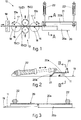
- the reference number 10 in the figures denotes generally the bending machine for round pieces 11 for reinforcement purposes using the perfected bending system according to the invention.
- the bending machine 10 is equipped with a drawing device 12 comprising a pair of rolls 15 arranged aligned substantially perpendicular to the round piece 11 in transit.
- the drawing device 12 cooperates with two bending assemblies, the first 13a and the second 13b, arranged respectively upstream and downstream thereof, and with a shearing assembly 14 arranged upstream of the first bending assembly 13a.
- the bending assemblies 13a, 13b shown are of the type with a rotary plate 18 and include a contrasting pin 16 and a bending pin 17.
- the bending machine 10 comprises, in this case, a limiting element 20 which extends lengthwise, substantially on an axis with the round piece 11 which is to be bent, and for a defined section, downstream of the second bending assembly 13b.
- the limiting element 20 lies on a plane at a desired height above the working plane 19 of the machine 10, or the bending plane of the round piece 11.
- the limiting element 20 consists of a metal shape of an open section comprising an upper face 20a and a side face 20b.
- the limiting element 20 has a transverse section which may be arched, rectangular or of another desired shape.
- the limiting element 20, in this case, pivots horizontally with respect to the working plane 19, in correspondence with its side face 20b, by means of a hinge 21.
- the movement of the limiting element 20 is obtained by means of two actuators 22 hinged at one end to the upper face 20a of the limiting element 20 and at the other end to the working plane 19.
- the rolls 15 of the drawing device 12 cause the round piece 11 to advance until it reaches the positions programmed for the first bends to be made.
- the axial twists and rotation cause the bends which have already been made to rise up, downstream of the drawing device 12.
- the lifting of the bends which have already been made is contained by the limiting element 20 as the upper face 20a of the limiting element 20 comes into contact with the section of round piece 11 which has already been bent.
- the position of the limiting element 20 is adjustable, it is possible to adapt the position thereof to the step and/or the type of bending to be carried out, or also to the bulk of the bends already made; it also allows the limiting element 20 to be discharged from the line of transit of the round piece 11 so that the final product obtained may be extracted more easily or for maintenance operations to be carried out.
- the rolls 15 of the drawing device 12 are taken from the position "I", where they are closed over the round piece 11, to a partially open position "II” (shown by a line of dashes) wherein they are taken to a position of non-contact and therefore release the round piece 11.
- Any contrasting and/or gripping means placed upstream or downstream of the drawing device 12 also open so as to completely release the round piece 11 from lateral contact.
- This lateral release causes the section of round piece 11 which has already been bent to fall due to its own weight, downstream of the drawing device 12, which is therefore returned to a resting position on the working plane 19 of the machine 10.
- the rolls 15 are repositioned in the closed position "I" so as to clamp the round piece 11, thus acting as a contrast to the bending, and then, once bending has been completed, so as to draw it into the position corresponding to the next bending.
- This procedure, of opening and then closing the rolls 15 on the round piece 11, can be carried out before all the bends, or only before some of them, according to the type of round piece 11, the type of feed (from a reel, in bars, etc.), the uniformity of the section of the round piece 11, its provenance, the type of final product which is to be obtained, etc.
Landscapes
- Engineering & Computer Science (AREA)
- Mechanical Engineering (AREA)
- Bending Of Plates, Rods, And Pipes (AREA)
- Wire Processing (AREA)
- Shaping Of Tube Ends By Bending Or Straightening (AREA)
Applications Claiming Priority (2)
| Application Number | Priority Date | Filing Date | Title |
|---|---|---|---|
| ITUD970082 | 1997-04-29 | ||
| IT97UD000082A IT1295107B1 (it) | 1997-04-29 | 1997-04-29 | Sistema di piegatura perfezionato per macchine piegatrici |
Publications (4)
| Publication Number | Publication Date |
|---|---|
| EP0875309A1 true EP0875309A1 (fr) | 1998-11-04 |
| EP0875309B1 EP0875309B1 (fr) | 2003-06-25 |
| EP0875309B2 EP0875309B2 (fr) | 2007-11-21 |
| EP0875309B9 EP0875309B9 (fr) | 2008-05-28 |
Family
ID=11422383
Family Applications (1)
| Application Number | Title | Priority Date | Filing Date |
|---|---|---|---|
| EP98106221A Expired - Lifetime EP0875309B9 (fr) | 1997-04-29 | 1998-04-06 | Système de pliage amélioré et machine à plier pour son exécution |
Country Status (9)
| Country | Link |
|---|---|
| US (1) | US5966979A (fr) |
| EP (1) | EP0875309B9 (fr) |
| JP (1) | JPH1128522A (fr) |
| AT (1) | ATE243574T1 (fr) |
| AU (1) | AU6190198A (fr) |
| DE (1) | DE69815749T3 (fr) |
| DK (1) | DK0875309T4 (fr) |
| ES (1) | ES2202677T5 (fr) |
| IT (1) | IT1295107B1 (fr) |
Cited By (4)
| Publication number | Priority date | Publication date | Assignee | Title |
|---|---|---|---|---|
| WO2003045603A1 (fr) * | 2001-11-30 | 2003-06-05 | M.E.P. Macchine Elettroniche Piegatrici Spa | Machine a plier conçue pour des profiles tels que des pieces circulaires de renfort ou des pieces analogues |
| ITBO20100488A1 (it) * | 2010-07-30 | 2012-01-31 | Schnell Spa | Dispositivo per la realizzazione di staffe tridimensionali |
| CN102615215A (zh) * | 2012-03-23 | 2012-08-01 | 冯广建 | 行梁式钢筋自动成型机 |
| CN107876658A (zh) * | 2017-11-06 | 2018-04-06 | 王庆香 | 一种工程建设用的钢筋折弯装置 |
Families Citing this family (5)
| Publication number | Priority date | Publication date | Assignee | Title |
|---|---|---|---|---|
| US8509926B2 (en) * | 2005-12-05 | 2013-08-13 | Fisher-Rosemount Systems, Inc. | Self-diagnostic process control loop for a process plant |
| KR101051122B1 (ko) | 2011-03-09 | 2011-07-21 | 태연기계주식회사 | 철근 자동 가공장치 |
| CN104043755B (zh) * | 2014-06-09 | 2016-02-10 | 建科机械(天津)股份有限公司 | 钢筋自动弯箍机的矫正箍筋扭转装置 |
| BG67466B1 (bg) * | 2019-10-10 | 2022-10-17 | Тодоров Киров Валентин | Автоматична машина и метод за производство на арматурни заготовки |
| CN114310346B (zh) * | 2022-03-11 | 2022-06-14 | 新乡职业技术学院 | 一种全自动管道折弯机 |
Citations (4)
| Publication number | Priority date | Publication date | Assignee | Title |
|---|---|---|---|---|
| CH336349A (fr) * | 1955-10-25 | 1959-02-28 | Soc D Anciens Etablissements J | Machine pour former les étriers destinés à une armature métallique de béton armé |
| EP0374465A1 (fr) * | 1988-11-23 | 1990-06-27 | M.E.P. Macchine Elettroniche Piegatrici S.p.A. | Installation ou appareil utilisant une machine de dressage et de pliage universelle |
| EP0537496A1 (fr) * | 1991-10-15 | 1993-04-21 | M.E.P. Macchine Elettroniche Piegatrici S.p.A. | Méthode pour cintrer des bouts de barres pour la construction civile avec des cintreuses coupantes, et cintreuses coupantes utilisant la méthode |
| EP0538595A1 (fr) * | 1991-10-21 | 1993-04-28 | M.E.P. Macchine Elettroniche Piegatrici S.p.A. | Cintreuse-formeuse avec plusieurs niveaux de travail |
Family Cites Families (9)
| Publication number | Priority date | Publication date | Assignee | Title |
|---|---|---|---|---|
| US3263471A (en) * | 1963-05-28 | 1966-08-02 | Western Electric Co | Heading apparatus |
| US3584660A (en) * | 1968-12-16 | 1971-06-15 | Nasa | Forming tool for ribbon or wire |
| JPS55126321A (en) * | 1979-03-20 | 1980-09-30 | Mitsui Eng & Shipbuild Co Ltd | Bending machine for metallic material |
| AT365484B (de) † | 1979-10-02 | 1982-01-25 | Evg Entwicklung Verwert Ges | Einrichtung zum automatischen zufuehren von stabmaterial zu einer biegemaschine fuer betonbewehrungsbuegel |
| IT1175134B (it) † | 1983-10-12 | 1987-07-01 | Piegatrici Macch Elettr | Metodo e mezzi per la realizzazione di sagomati con macchine piegatrici di tondo o filo particolarmente laminato a caldo di basso costo per migliorare la qualita' del prodotto finito |
| US4590779A (en) * | 1984-09-18 | 1986-05-27 | Tools For Bending, Inc. | Program-controlled frame bending method and apparatus |
| IT1242690B (it) † | 1990-12-17 | 1994-05-17 | Piegatrici Macch Elettr | Macchina piegatrice sagomatrice per profilati e procedimento di piegatura in coda di profilati. |
| EP0592798B1 (fr) * | 1992-09-15 | 1997-06-11 | M.E.P. Macchine Elettroniche Piegatrici S.p.A. | Méthode de cintrage et appareil relatifs à cette méthode |
| US5511402A (en) * | 1994-12-16 | 1996-04-30 | Kauffman; Kenneth A. | Optimizing controller |
-
1997
- 1997-04-29 IT IT97UD000082A patent/IT1295107B1/it active IP Right Grant
-
1998
- 1998-04-06 ES ES98106221T patent/ES2202677T5/es not_active Expired - Lifetime
- 1998-04-06 DK DK98106221T patent/DK0875309T4/da active
- 1998-04-06 AT AT98106221T patent/ATE243574T1/de active
- 1998-04-06 DE DE69815749T patent/DE69815749T3/de not_active Expired - Lifetime
- 1998-04-06 EP EP98106221A patent/EP0875309B9/fr not_active Expired - Lifetime
- 1998-04-09 AU AU61901/98A patent/AU6190198A/en not_active Abandoned
- 1998-04-24 US US09/065,455 patent/US5966979A/en not_active Expired - Lifetime
- 1998-04-30 JP JP10121192A patent/JPH1128522A/ja active Pending
Patent Citations (4)
| Publication number | Priority date | Publication date | Assignee | Title |
|---|---|---|---|---|
| CH336349A (fr) * | 1955-10-25 | 1959-02-28 | Soc D Anciens Etablissements J | Machine pour former les étriers destinés à une armature métallique de béton armé |
| EP0374465A1 (fr) * | 1988-11-23 | 1990-06-27 | M.E.P. Macchine Elettroniche Piegatrici S.p.A. | Installation ou appareil utilisant une machine de dressage et de pliage universelle |
| EP0537496A1 (fr) * | 1991-10-15 | 1993-04-21 | M.E.P. Macchine Elettroniche Piegatrici S.p.A. | Méthode pour cintrer des bouts de barres pour la construction civile avec des cintreuses coupantes, et cintreuses coupantes utilisant la méthode |
| EP0538595A1 (fr) * | 1991-10-21 | 1993-04-28 | M.E.P. Macchine Elettroniche Piegatrici S.p.A. | Cintreuse-formeuse avec plusieurs niveaux de travail |
Cited By (6)
| Publication number | Priority date | Publication date | Assignee | Title |
|---|---|---|---|---|
| WO2003045603A1 (fr) * | 2001-11-30 | 2003-06-05 | M.E.P. Macchine Elettroniche Piegatrici Spa | Machine a plier conçue pour des profiles tels que des pieces circulaires de renfort ou des pieces analogues |
| US7104102B2 (en) | 2001-11-30 | 2006-09-12 | M.E.P. Macchine Elettroniche Piegatrici Spa | Bending machine for profiles such as reinforcement round pieces or similar |
| ITBO20100488A1 (it) * | 2010-07-30 | 2012-01-31 | Schnell Spa | Dispositivo per la realizzazione di staffe tridimensionali |
| CN102615215A (zh) * | 2012-03-23 | 2012-08-01 | 冯广建 | 行梁式钢筋自动成型机 |
| CN102615215B (zh) * | 2012-03-23 | 2014-02-05 | 冯广建 | 行梁式钢筋自动成型机 |
| CN107876658A (zh) * | 2017-11-06 | 2018-04-06 | 王庆香 | 一种工程建设用的钢筋折弯装置 |
Also Published As
| Publication number | Publication date |
|---|---|
| EP0875309B9 (fr) | 2008-05-28 |
| ITUD970082A1 (it) | 1998-10-29 |
| ATE243574T1 (de) | 2003-07-15 |
| ES2202677T5 (es) | 2008-05-01 |
| ES2202677T3 (es) | 2004-04-01 |
| DE69815749T3 (de) | 2008-07-03 |
| IT1295107B1 (it) | 1999-04-30 |
| DE69815749D1 (de) | 2003-07-31 |
| EP0875309B2 (fr) | 2007-11-21 |
| JPH1128522A (ja) | 1999-02-02 |
| DE69815749T2 (de) | 2004-04-29 |
| DK0875309T4 (da) | 2008-05-13 |
| EP0875309B1 (fr) | 2003-06-25 |
| US5966979A (en) | 1999-10-19 |
| ITUD970082A0 (fr) | 1997-04-29 |
| AU6190198A (en) | 1998-11-05 |
| DK0875309T3 (da) | 2003-10-20 |
Similar Documents
| Publication | Publication Date | Title |
|---|---|---|
| US4993253A (en) | Drawing unit downstream of a bending assembly and method to bend the trailing end of bars | |
| EP0875309B1 (fr) | Système de pliage amélioré et machine à plier pour son exécution | |
| DE102012220273B4 (de) | Kettenbiegemaschine | |
| EP3921097B1 (fr) | Machine pour le travail de barres et procédé de travail correspondant | |
| EP0194478B1 (fr) | Dispositif pour dresser des barres en évitant une rotation relative des éléments successives autour de l'axe longitudinal | |
| DE2716917C2 (fr) | ||
| WO2005016574A1 (fr) | Procede de cintrage de pieces d'usinage | |
| US7004003B2 (en) | Bending machine for profiles | |
| EP2299831B1 (fr) | Procédé et dispositif pour former des bretzels | |
| DE69408510T2 (de) | Verfahren und Vorrichtung zur Formung von rechteckigen gekrümmten Nadeln | |
| DE102005047078B3 (de) | Biegemaschine, insbesondere Seilbiegemaschine | |
| DE3902450C2 (fr) | ||
| EP0882529A1 (fr) | Procédé de pliage avec une unité de pliage mobile et machine de façonnage | |
| US20040187540A1 (en) | Bending machine for profiles and relative bending method | |
| DE2920280C3 (de) | Vorrichtung zum Transportieren von Külbeln in einer IS-Glasformmaschine | |
| DE60114045T2 (de) | Vorrichtung zur vervollständigung von verstärkungskäfigen und entsprechendes verfahren | |
| EP0286587B1 (fr) | Procédé de profilage d'objets annulaires et dispositif pour la mise en oeuvre dudit procédé | |
| CN213968476U (zh) | 一种高强钢辊压成型在线三维弯曲成型装置 | |
| CN209077661U (zh) | 一种金属丝的拉伸剪切折弯一体机 | |
| WO2012055608A1 (fr) | Dispositif et procédé pour l'introduction d'une bande métallique dans une installation de traitement de bande métallique | |
| EP0509232A1 (fr) | Unité d'alignement et d'étirage en aval d'une bobine | |
| US6449999B1 (en) | Device for feeding the front end of a wire coil into a drawing installation | |
| AT394958B (de) | Vorrichtung zum biegen von stahlstaeben zu betonbewehrungselementen | |
| EP1689542A2 (fr) | Procede de forge et d'estampage, et dispositif d'estampage pour la mise en oeuvre de ce procede | |
| CN216606739U (zh) | 在线矫直导卫 |
Legal Events
| Date | Code | Title | Description |
|---|---|---|---|
| PUAI | Public reference made under article 153(3) epc to a published international application that has entered the european phase |
Free format text: ORIGINAL CODE: 0009012 |
|
| AK | Designated contracting states |
Kind code of ref document: A1 Designated state(s): AT BE CH DE DK ES FR GB GR IE IT LI NL PT SE |
|
| AX | Request for extension of the european patent |
Free format text: AL;LT;LV;MK;RO;SI |
|
| 17P | Request for examination filed |
Effective date: 19990421 |
|
| AKX | Designation fees paid |
Free format text: AT BE CH DE DK ES FR GB GR IE IT LI NL PT SE |
|
| 17Q | First examination report despatched |
Effective date: 20020304 |
|
| GRAH | Despatch of communication of intention to grant a patent |
Free format text: ORIGINAL CODE: EPIDOS IGRA |
|
| RTI1 | Title (correction) |
Free format text: PERFECTED BENDING SYSTEM AND RELATIVE BENDING MACHINE |
|
| GRAH | Despatch of communication of intention to grant a patent |
Free format text: ORIGINAL CODE: EPIDOS IGRA |
|
| GRAA | (expected) grant |
Free format text: ORIGINAL CODE: 0009210 |
|
| RTI1 | Title (correction) |
Free format text: PERFECTED BENDING METHOD FOR BENDING MACHINES AND RELATIVE BENDING MACHINE |
|
| AK | Designated contracting states |
Designated state(s): AT BE CH DE DK ES FR GB GR IE IT LI NL PT SE |
|
| REG | Reference to a national code |
Ref country code: GB Ref legal event code: FG4D |
|
| REG | Reference to a national code |
Ref country code: CH Ref legal event code: EP |
|
| REG | Reference to a national code |
Ref country code: SE Ref legal event code: TRGR |
|
| REG | Reference to a national code |
Ref country code: IE Ref legal event code: FG4D |
|
| REF | Corresponds to: |
Ref document number: 69815749 Country of ref document: DE Date of ref document: 20030731 Kind code of ref document: P |
|
| PG25 | Lapsed in a contracting state [announced via postgrant information from national office to epo] |
Ref country code: PT Free format text: LAPSE BECAUSE OF FAILURE TO SUBMIT A TRANSLATION OF THE DESCRIPTION OR TO PAY THE FEE WITHIN THE PRESCRIBED TIME-LIMIT Effective date: 20030925 |
|
| REG | Reference to a national code |
Ref country code: CH Ref legal event code: NV Representative=s name: PATMED AG |
|
| REG | Reference to a national code |
Ref country code: GR Ref legal event code: EP Ref document number: 20030403842 Country of ref document: GR |
|
| ET | Fr: translation filed | ||
| PLBQ | Unpublished change to opponent data |
Free format text: ORIGINAL CODE: EPIDOS OPPO |
|
| PLBI | Opposition filed |
Free format text: ORIGINAL CODE: 0009260 |
|
| PG25 | Lapsed in a contracting state [announced via postgrant information from national office to epo] |
Ref country code: IE Free format text: LAPSE BECAUSE OF NON-PAYMENT OF DUE FEES Effective date: 20040406 |
|
| PLAX | Notice of opposition and request to file observation + time limit sent |
Free format text: ORIGINAL CODE: EPIDOSNOBS2 |
|
| 26 | Opposition filed |
Opponent name: SCHNELL S.P.A Effective date: 20040325 |
|
| PLBB | Reply of patent proprietor to notice(s) of opposition received |
Free format text: ORIGINAL CODE: EPIDOSNOBS3 |
|
| NLR1 | Nl: opposition has been filed with the epo |
Opponent name: SCHNELL S.P.A |
|
| REG | Reference to a national code |
Ref country code: IE Ref legal event code: MM4A |
|
| PLAY | Examination report in opposition despatched + time limit |
Free format text: ORIGINAL CODE: EPIDOSNORE2 |
|
| PG25 | Lapsed in a contracting state [announced via postgrant information from national office to epo] |
Ref country code: IT Free format text: LAPSE BECAUSE OF NON-PAYMENT OF DUE FEES Effective date: 20050406 |
|
| PLAY | Examination report in opposition despatched + time limit |
Free format text: ORIGINAL CODE: EPIDOSNORE2 |
|
| PLBC | Reply to examination report in opposition received |
Free format text: ORIGINAL CODE: EPIDOSNORE3 |
|
| PLCK | Communication despatched that opposition was rejected |
Free format text: ORIGINAL CODE: EPIDOSNREJ1 |
|
| APBP | Date of receipt of notice of appeal recorded |
Free format text: ORIGINAL CODE: EPIDOSNNOA2O |
|
| APAH | Appeal reference modified |
Free format text: ORIGINAL CODE: EPIDOSCREFNO |
|
| APBQ | Date of receipt of statement of grounds of appeal recorded |
Free format text: ORIGINAL CODE: EPIDOSNNOA3O |
|
| APAH | Appeal reference modified |
Free format text: ORIGINAL CODE: EPIDOSCREFNO |
|
| APBU | Appeal procedure closed |
Free format text: ORIGINAL CODE: EPIDOSNNOA9O |
|
| PUAH | Patent maintained in amended form |
Free format text: ORIGINAL CODE: 0009272 |
|
| STAA | Information on the status of an ep patent application or granted ep patent |
Free format text: STATUS: PATENT MAINTAINED AS AMENDED |
|
| 27A | Patent maintained in amended form |
Effective date: 20071121 |
|
| AK | Designated contracting states |
Kind code of ref document: B2 Designated state(s): AT BE CH DE DK ES FR GB GR IE IT LI NL PT SE |
|
| REG | Reference to a national code |
Ref country code: CH Ref legal event code: AEN Free format text: AUFRECHTERHALTUNG DES PATENTES IN GEAENDERTER FORM |
|
| NLR2 | Nl: decision of opposition |
Effective date: 20071121 |
|
| REG | Reference to a national code |
Ref country code: SE Ref legal event code: RPEO |
|
| REG | Reference to a national code |
Ref country code: GR Ref legal event code: EP Ref document number: 20080400476 Country of ref document: GR |
|
| NLR3 | Nl: receipt of modified translations in the netherlands language after an opposition procedure | ||
| REG | Reference to a national code |
Ref country code: ES Ref legal event code: DC2A Date of ref document: 20080220 Kind code of ref document: T5 |
|
| REG | Reference to a national code |
Ref country code: DK Ref legal event code: T4 |
|
| NLR4 | Nl: receipt of corrected translation in the netherlands language at the initiative of the proprietor of the patent | ||
| ET3 | Fr: translation filed ** decision concerning opposition | ||
| REG | Reference to a national code |
Ref country code: SE Ref legal event code: RPOT |
|
| PGRI | Patent reinstated in contracting state [announced from national office to epo] |
Ref country code: IT Effective date: 20091201 |
|
| REG | Reference to a national code |
Ref country code: FR Ref legal event code: PLFP Year of fee payment: 19 |
|
| REG | Reference to a national code |
Ref country code: FR Ref legal event code: PLFP Year of fee payment: 20 |
|
| PGFP | Annual fee paid to national office [announced via postgrant information from national office to epo] |
Ref country code: NL Payment date: 20170419 Year of fee payment: 20 |
|
| PGFP | Annual fee paid to national office [announced via postgrant information from national office to epo] |
Ref country code: GB Payment date: 20170426 Year of fee payment: 20 Ref country code: CH Payment date: 20170419 Year of fee payment: 20 Ref country code: DE Payment date: 20170419 Year of fee payment: 20 Ref country code: FR Payment date: 20170419 Year of fee payment: 20 Ref country code: GR Payment date: 20170425 Year of fee payment: 20 Ref country code: DK Payment date: 20170419 Year of fee payment: 20 |
|
| PGFP | Annual fee paid to national office [announced via postgrant information from national office to epo] |
Ref country code: IT Payment date: 20170413 Year of fee payment: 20 Ref country code: ES Payment date: 20170517 Year of fee payment: 20 Ref country code: AT Payment date: 20170420 Year of fee payment: 20 Ref country code: BE Payment date: 20170419 Year of fee payment: 20 Ref country code: SE Payment date: 20170419 Year of fee payment: 20 |
|
| REG | Reference to a national code |
Ref country code: DE Ref legal event code: R071 Ref document number: 69815749 Country of ref document: DE |
|
| REG | Reference to a national code |
Ref country code: DK Ref legal event code: EUP Effective date: 20180406 |
|
| REG | Reference to a national code |
Ref country code: NL Ref legal event code: MK Effective date: 20180405 |
|
| REG | Reference to a national code |
Ref country code: CH Ref legal event code: PL |
|
| REG | Reference to a national code |
Ref country code: GB Ref legal event code: PE20 Expiry date: 20180405 Ref country code: BE Ref legal event code: MK Effective date: 20180406 |
|
| REG | Reference to a national code |
Ref country code: AT Ref legal event code: MK07 Ref document number: 243574 Country of ref document: AT Kind code of ref document: T Effective date: 20180406 |
|
| REG | Reference to a national code |
Ref country code: SE Ref legal event code: EUG |
|
| PG25 | Lapsed in a contracting state [announced via postgrant information from national office to epo] |
Ref country code: GB Free format text: LAPSE BECAUSE OF EXPIRATION OF PROTECTION Effective date: 20180405 |
|
| REG | Reference to a national code |
Ref country code: ES Ref legal event code: FD2A Effective date: 20210111 |
|
| PG25 | Lapsed in a contracting state [announced via postgrant information from national office to epo] |
Ref country code: ES Free format text: LAPSE BECAUSE OF EXPIRATION OF PROTECTION Effective date: 20180407 |