EP0537618A1 - Procédé et dispositif pour tréfilage - Google Patents
Procédé et dispositif pour tréfilage Download PDFInfo
- Publication number
- EP0537618A1 EP0537618A1 EP92117155A EP92117155A EP0537618A1 EP 0537618 A1 EP0537618 A1 EP 0537618A1 EP 92117155 A EP92117155 A EP 92117155A EP 92117155 A EP92117155 A EP 92117155A EP 0537618 A1 EP0537618 A1 EP 0537618A1
- Authority
- EP
- European Patent Office
- Prior art keywords
- wire
- reduction
- die
- dies
- cross
- Prior art date
- Legal status (The legal status is an assumption and is not a legal conclusion. Google has not performed a legal analysis and makes no representation as to the accuracy of the status listed.)
- Granted
Links
Images


Classifications
-
- B—PERFORMING OPERATIONS; TRANSPORTING
- B21—MECHANICAL METAL-WORKING WITHOUT ESSENTIALLY REMOVING MATERIAL; PUNCHING METAL
- B21C—MANUFACTURE OF METAL SHEETS, WIRE, RODS, TUBES, PROFILES OR LIKE SEMI-MANUFACTURED PRODUCTS OTHERWISE THAN BY ROLLING; AUXILIARY OPERATIONS USED IN CONNECTION WITH METAL-WORKING WITHOUT ESSENTIALLY REMOVING MATERIAL
- B21C1/00—Manufacture of metal sheets, wire, rods, tubes or like semi-manufactured products by drawing
-
- B—PERFORMING OPERATIONS; TRANSPORTING
- B21—MECHANICAL METAL-WORKING WITHOUT ESSENTIALLY REMOVING MATERIAL; PUNCHING METAL
- B21C—MANUFACTURE OF METAL SHEETS, WIRE, RODS, TUBES, PROFILES OR LIKE SEMI-MANUFACTURED PRODUCTS OTHERWISE THAN BY ROLLING; AUXILIARY OPERATIONS USED IN CONNECTION WITH METAL-WORKING WITHOUT ESSENTIALLY REMOVING MATERIAL
- B21C1/00—Manufacture of metal sheets, wire, rods, tubes or like semi-manufactured products by drawing
- B21C1/02—Drawing metal wire or like flexible metallic material by drawing machines or apparatus in which the drawing action is effected by drums
- B21C1/04—Drawing metal wire or like flexible metallic material by drawing machines or apparatus in which the drawing action is effected by drums with two or more dies operating in series
- B21C1/06—Drawing metal wire or like flexible metallic material by drawing machines or apparatus in which the drawing action is effected by drums with two or more dies operating in series in which the material slips on the drums
-
- B—PERFORMING OPERATIONS; TRANSPORTING
- B21—MECHANICAL METAL-WORKING WITHOUT ESSENTIALLY REMOVING MATERIAL; PUNCHING METAL
- B21C—MANUFACTURE OF METAL SHEETS, WIRE, RODS, TUBES, PROFILES OR LIKE SEMI-MANUFACTURED PRODUCTS OTHERWISE THAN BY ROLLING; AUXILIARY OPERATIONS USED IN CONNECTION WITH METAL-WORKING WITHOUT ESSENTIALLY REMOVING MATERIAL
- B21C1/00—Manufacture of metal sheets, wire, rods, tubes or like semi-manufactured products by drawing
- B21C1/02—Drawing metal wire or like flexible metallic material by drawing machines or apparatus in which the drawing action is effected by drums
- B21C1/04—Drawing metal wire or like flexible metallic material by drawing machines or apparatus in which the drawing action is effected by drums with two or more dies operating in series
Definitions
- wire is drawn through a plurality of dies in a wire drawing machine whereby the cross section of the wire is reduced by a constant reduction at each die.
- the total reduction at the final two dies is equal to the constant reduction.
- the wire is reduced by about 10 ⁇ % to about 90 ⁇ % of the typical reduction at the next to last die and the remainder of the reduction at the final die.
- the hardness of drawn steel wire results from the plastic deformation associated with the drawing process.
- the wire increases in hardness as it proceeds through the wire drawing machine. If the wire becomes too hard or brittle, breakage occurs during the drawing process or when the wire is subjected to torsion or bending.
- the central burst effect can be prevented by controlling the process geometries. That is, the die angle and the percent reduction in area are selected to avoid the "Central Bursting Zone" illustrated in Figure 3 of the present drawings.
- the central bursting zone defines die geometries for which non-uniform deformation through the cross section of the wire is expected. Die geometries defining the central bursting zone do not always result in central bursting. These geometries will, however, always induce the tensile, longitudinal stresses in the wire center and the compressive, longitudinal stresses at the wire surface that can cause voids and fracture during subsequent drawing steps or when the drawn wire is subjected to torsional loading.
- Strain introduced into the wire by the drawing process increases the tensile strength of the wire.
- this increase is held constant at every die of the draft in a wire drawing machine. Analyses of the formation of central bursts show that bursting is more likely to occur if the increase in tensile strength remains low. Therefore, the wire is drawn through a draft of many dies each having a geometry to avoid the central burst zone. Reducing the number of dies in the draft results in a higher reduction of area at each die. This in turn results in an increase in both the heat generated and die wear. To obviate these problems, the wire drawing industry is continually trying to improve the quality of wire drawn products. An ongoing search, therefore, continues for improvements in processing and/or equipment design to economically manufacture wire, such as high tensile strength wire.
- Wire drawing machines are typically designed to draw wire through a draft of nineteen to twenty-one dies.
- the article by Zimmerman, et al. evaluates data of a 1.1 millimeters (mm.) diameter wire drawn to a .22 mm. diameter through nineteen dies each having 12 degree included angles.
- the reduction at each step was about 16%. This reduction was just below the curve in the central bursting zone, as illustrated in the graph of Figure 3 herein.
- increasing the reduction in area of wire at a die increases the speed of manufacture and reduces the number of dies needed to draw the wire to a desired size.
- the increase in reduction is particularly advantageous because it reduces the central bursting zone effect.
- Ductility of high strength, steel wire is particularly important when the wire is subjected to plastic deformation during manufacture, such as from twisting a plurality of wires into a multi-wire strand.
- Torsion testing indicating the minimum number of twists to failure, is a common method of testing wire ductility. Maximum ductility occurs when there is uniform twisting along a gauge length and the final fracture is straight and transverse to the wire axis. Strain localization and delamination (longitudinal splitting) are qualitative indications of a decrease in ductility, ie., fewer number of twists to failure.
- the cross section of the wire is typically reduced by a reduction of about 15% to about 18% at all but the final two dies.
- the cross section of the wire at the final two dies is reduced by a total amount substantially equal to the reduction at a single standard die.
- the reduction at the next to final die is about 10 ⁇ % to about 90 ⁇ % of the typical reduction at a standard die with the remainder at the final die.
- the wire is reduced at each of the plurality of standard dies by a typical reduction of about 15.5%.
- Both the standard dies and the final two dies have a die angle of about 12 degrees.
- an apparatus for drawing steel wire to produce high tensile strength, steel wire with increased torsional ductility comprises a plurality of dies arranged in a wire drawing device; each of said plurality of dies reduces the cross section of the wire by a constant reduction of about 15% to about 18%; and a next to last die and a final die in said wire drawing device reducing the cross section of the wire by a total reduction substantially equal to the constant reduction, said next to last die reducing the cross section of the wire by a reduction of about 10 ⁇ % to about 90 ⁇ % of the constant reduction and the remainder of the cross section being reduced at said final die.
- a high tensile strength, steel wire with increased torsional ductility formed by the method of drawing steel wire comprising the steps of: drawing wire through a plurality of dies arranged in a wire drawing device; reducing the cross section of the wire by a constant reduction of about 15% to about 18% at each of the plurality of dies; and reducing the cross section of the wire at a next to last die and at a final die in said wire drawing device by a total reduction substantially equal to the constant reduction, said next to last die reducing the cross section of the wire by about 10 ⁇ % to about 90 ⁇ % of the constant reduction and the remainder of the cross section being reduced at said final die.
- the cross section of the wire is typically reduced by a reduction of about 15% to about 18% at all but the final die.
- the wire reduction at the last die is between about 10 ⁇ % to about 90 ⁇ % of the typical reduction.
- the reduction at the final die is about 30 ⁇ % to about 70 ⁇ % of the typical reduction and most preferably, the reduction at the final die is about 55% of the typical reduction.
- a method of drawing steel wire to produce high tensile strength, steel wire with increased torsional ductility comprises the steps of: drawing wire through a plurality of dies arranged in a wire drawing device; reducing the cross section of the wire by a constant reduction of about 15% to about 18% at each of the of the dies; and reducing the cross section of the wire at a final die by a reduction of about 10 ⁇ % to about 90 ⁇ % of the constant reduction.
- the tensile strength of carbon steel can be increased by small additions of alloying elements, usually less than 1.0 ⁇ %. These are called “micro-alloyed steels.” High tensile strength steels having a high level of ductility and outstanding fatigue resistance are described in U.S. Patent No. 4,960 ⁇ ,473, which is incorporated herein by reference. Brass is an alloy of copper and zinc which can contain other metals in varying lesser amounts. The ternary alloys employed as coatings in this invention are iron-brass alloys since they contain 0 ⁇ .1 to 10 ⁇ percent iron.
- the wire 12 passes directly from each standard die 14 to its drawing capstan 16 and then to the next die.
- the wire is drawn over capstans 16 with each succeeding capstan running faster than the preceding one to compensate for wire elongation.
- the reduction in the cross sectional area of the wire between the capstans on this machine with a straight draft, is a substantially fixed or standard value. This insures a lower velocity of the wire being drawn than the peripheral velocity of the drawing capstans.
- the resulting positive slip insures that all portions of the wire are taut and that there is adequate frictional force exerted on the wire by the capstan to pull the wire through the dies. Without this force, the loads and subsequent positions in the wire drawing machine are excessive and wire breakage occurs.
- the first embodiment reduces steel wire by a constant reduction of about 15% to about 18% at each standard die 14.
- the cross section of the wire is reduced at each die 14 by a constant reduction of about 15.5%.
- the final two dies 18 and 19 are disposed between the last two capstans.
- An important aspect of the invention is that the total reduction of the cross section of the wire at the final two dies 18 and 19 is substantially equal to the reduction at one of the preceding, standard dies.
- the reduction in the next to last die 18 is about 10 ⁇ % to about 90 ⁇ % of the constant reduction at the preceding, standard dies 14 and the remaining reduction is at the final die 19.
- FIG. 2 illustrates a standard die 14 having a die angle a, a bearing surface b, a back relief angle c and an inlet opening diameter d.
- Each standard die 14 has a die angle of about 8 to about 16 degrees.
- each die 14 has a die angle of about 12 degrees.
- the drawn wire was subjected to torsional testing. That is, a length of drawn wire was secured at either end. One end of the wire was turned relative to the other end, ie., twisted twenty-four, 360 ⁇ degree turns.
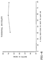
- the graph of Figure 5 illustrates the average results of subjecting the wire formed by the new process and apparatus to the same test as the prior art processed wire was subjected.
- the torque increased sharply for six, 360 ⁇ degree turns.
- the torque then gradually increased until fracture at or about seventy six turns.
- the filament can withstand almost seventy, 360 ⁇ degree twists until normal torsion fracture.
- the graph of Figure 6 illustrates that when wire is subjected to a yet higher final reduction at the next to last die, ie. about 80 ⁇ % (compared with the reduction at a standard die), the number of twists before normal tension fracture begins to decrease. Therefore, a reduction of about 90 ⁇ % of the constant reduction at the next to last die is thought to be an approximate limit before the torsional ductility is approximately equal to that resulting from the prior art processing.
- a second embodiment, incorporating the apparatus and method of operating the apparatus as illustrated in Figure 7, is thought to be effective for producing high tensile strength, steel wire with increased torsional ductility.
- the second embodiment is similar to the first embodiment except that all of the dies in the draft are standard dies with a constant reduction with the exception of the last die 20 ⁇ .
- the reduction of the wire at the final die 20 ⁇ is between about 10 ⁇ % to about 90 ⁇ % of the constant reduction.
- Preferably, about 30 ⁇ % to about 70 ⁇ % of the constant reduction is taken at final die 20 ⁇ .
- Most preferably, about 55% of the constant reduction is taken at the final die.
- steel wire processed with the apparatus of the second embodiment provides the high tensile strength and increased torsional ductility of the steel wire produced in accordance with the first embodiment.
- the reduction at each of the standard dies is slightly more than the reduction of the standard dies in the first embodiment. Then, the same number of standard dies can be used as in the first embodiment to achieve the same total reduction in the cros sectional area of the wire.
- the present invention is directed to a wire drawing machine incorporating a straight draft
- the advantage of a tapered draft is that the cross sectional area of the wire is reduced in a fewer number of dies. With a tapered draft, the amount of reduction in cross section of the wire would be larger at the first dies than with the dies in the constant draft. The amount of reduction at each draft would then become increasingly less until the last few dies. As previously discussed, the process geometries, such as the amount of reduction in each die and the die angle would still be carefully controlled to avoid falling within the central bursting zone of Figure 3.
Landscapes
- Engineering & Computer Science (AREA)
- Mechanical Engineering (AREA)
- Metal Extraction Processes (AREA)
Applications Claiming Priority (2)
| Application Number | Priority Date | Filing Date | Title |
|---|---|---|---|
| US776948 | 1991-10-15 | ||
| US07/776,948 US5189897A (en) | 1991-10-15 | 1991-10-15 | Method and apparatus for wire drawing |
Publications (2)
| Publication Number | Publication Date |
|---|---|
| EP0537618A1 true EP0537618A1 (fr) | 1993-04-21 |
| EP0537618B1 EP0537618B1 (fr) | 1996-04-17 |
Family
ID=25108829
Family Applications (1)
| Application Number | Title | Priority Date | Filing Date |
|---|---|---|---|
| EP92117155A Expired - Lifetime EP0537618B1 (fr) | 1991-10-15 | 1992-10-08 | Procédé et dispositif pour tréfilage |
Country Status (8)
| Country | Link |
|---|---|
| US (1) | US5189897A (fr) |
| EP (1) | EP0537618B1 (fr) |
| JP (1) | JP3274504B2 (fr) |
| KR (1) | KR100245937B1 (fr) |
| AU (1) | AU655326B2 (fr) |
| BR (1) | BR9203927A (fr) |
| CA (1) | CA2058909A1 (fr) |
| ES (1) | ES2087393T3 (fr) |
Cited By (4)
| Publication number | Priority date | Publication date | Assignee | Title |
|---|---|---|---|---|
| WO2000006316A1 (fr) * | 1998-07-27 | 2000-02-10 | I.Fi.Co.M. S.R.L., Immobiliare Finanziaria Costruzioni Milano | Procede ameliore d'etirage de fil metallique et outil de mise en application du procede |
| US6049042A (en) * | 1997-05-02 | 2000-04-11 | Avellanet; Francisco J. | Electrical cables and methods of making same |
| EP1013819A4 (fr) * | 1997-05-21 | 2004-04-28 | Bridgestone Corp | Cable acier et son procede de production |
| CN103874552A (zh) * | 2011-10-09 | 2014-06-18 | 贝卡尔特公司 | 锯丝 |
Families Citing this family (17)
| Publication number | Priority date | Publication date | Assignee | Title |
|---|---|---|---|---|
| JP2500786B2 (ja) * | 1992-11-16 | 1996-05-29 | 株式会社神戸製鋼所 | 熱間圧延鋼線材、極細鋼線および撚鋼線、並びに極細鋼線の製造法 |
| JP3340233B2 (ja) | 1993-04-06 | 2002-11-05 | 新日本製鐵株式会社 | 捻回特性の優れた高強度鋼線およびその製造方法 |
| KR960011666B1 (ko) * | 1994-08-25 | 1996-08-29 | 유의수 | 주석도금선의 인장강도 조절방법 |
| US5535612A (en) * | 1994-10-21 | 1996-07-16 | The Goodyear Tire & Rubber Company | Method and apparatus for drawing wire through a plurality of standard dies at the die positions |
| US6449834B1 (en) | 1997-05-02 | 2002-09-17 | Scilogy Corp. | Electrical conductor coils and methods of making same |
| US6399886B1 (en) | 1997-05-02 | 2002-06-04 | General Science & Technology Corp. | Multifilament drawn radiopaque high elastic cables and methods of making the same |
| JP4521741B2 (ja) | 1999-06-25 | 2010-08-11 | 大日本印刷株式会社 | カラーフィルタの欠陥修正方法 |
| US7188503B2 (en) * | 2004-10-29 | 2007-03-13 | The Goodyear Tire + Rubber Company | Fine wire drawing machine |
| US7617713B2 (en) * | 2004-12-14 | 2009-11-17 | The Goodyear Tire + Rubber Company, Inc. | Final die for wire drawing machines |
| KR100657052B1 (ko) * | 2006-01-05 | 2006-12-14 | 고려강선주식회사 | 스틸 코드용 선재의 습식 신선 방법 |
| JP2008069409A (ja) * | 2006-09-14 | 2008-03-27 | Bridgestone Corp | 高強度高炭素鋼線およびその製造方法 |
| US20080173063A1 (en) * | 2007-01-23 | 2008-07-24 | Thomas Wilson Tyl | Torsional wire treatment drawing system |
| CN101952060B (zh) * | 2008-01-25 | 2012-12-12 | 株式会社普利司通 | 镀铜钢丝的制造方法和镀铜钢丝的拉丝装置 |
| ES2529299T3 (es) | 2008-10-30 | 2015-02-18 | Bridgestone Corporation | Alambre de acero al carbono con alta resistencia y excelente ductilidad y resistencia a fatiga, proceso de producción del mismo y método de evaluación |
| US8256085B2 (en) * | 2008-11-17 | 2012-09-04 | Lincoln Global, Inc. | System and method for classifying wire |
| CN106501108A (zh) * | 2016-09-09 | 2017-03-15 | 中国电力科学研究院 | 一种 opgw 单线扭转疲劳试验方法及装置 |
| CN109500114A (zh) * | 2018-11-04 | 2019-03-22 | 江苏兴达钢帘线股份有限公司 | 一种可抑制分层的特高强度单丝拉拔方法及装置 |
Citations (1)
| Publication number | Priority date | Publication date | Assignee | Title |
|---|---|---|---|---|
| FR1181963A (fr) * | 1957-09-03 | 1959-06-19 | Norton Co Ltd Sir James Farmer | Perfectionnements aux machines de tréfilerie et aux bancs à tréfiler |
Family Cites Families (7)
| Publication number | Priority date | Publication date | Assignee | Title |
|---|---|---|---|---|
| US2715959A (en) * | 1951-02-17 | 1955-08-23 | John A Roebling S Sons Corp | Multiblock wire-drawing apparatus and method |
| US3299687A (en) * | 1964-09-15 | 1967-01-24 | Nat Res Corp | Metallurgy |
| US3486361A (en) * | 1967-07-20 | 1969-12-30 | Babcock & Wilcox Co | Strengthening of elongated metal sections |
| DE1946221A1 (de) * | 1969-09-12 | 1971-04-15 | Henrich Kommanditgesellschaft | Drahtziehmaschine |
| US3955390A (en) * | 1973-02-21 | 1976-05-11 | Brunswick Corporation | Twist drawn wire, process and apparatus for making same |
| JPS5954416A (ja) * | 1982-09-24 | 1984-03-29 | Toshiba Corp | タングステン線の製造方法 |
| US4960473A (en) * | 1989-10-02 | 1990-10-02 | The Goodyear Tire & Rubber Company | Process for manufacturing steel filament |
-
1991
- 1991-10-15 US US07/776,948 patent/US5189897A/en not_active Expired - Lifetime
-
1992
- 1992-01-07 CA CA002058909A patent/CA2058909A1/fr not_active Abandoned
- 1992-10-08 BR BR929203927A patent/BR9203927A/pt not_active IP Right Cessation
- 1992-10-08 EP EP92117155A patent/EP0537618B1/fr not_active Expired - Lifetime
- 1992-10-08 ES ES92117155T patent/ES2087393T3/es not_active Expired - Lifetime
- 1992-10-08 JP JP27037392A patent/JP3274504B2/ja not_active Expired - Fee Related
- 1992-10-14 AU AU27012/92A patent/AU655326B2/en not_active Ceased
- 1992-10-14 KR KR1019920018910A patent/KR100245937B1/ko not_active Expired - Fee Related
Patent Citations (1)
| Publication number | Priority date | Publication date | Assignee | Title |
|---|---|---|---|---|
| FR1181963A (fr) * | 1957-09-03 | 1959-06-19 | Norton Co Ltd Sir James Farmer | Perfectionnements aux machines de tréfilerie et aux bancs à tréfiler |
Non-Patent Citations (2)
| Title |
|---|
| PATENT ABSTRACTS OF JAPAN vol. 7, no. 63 (M-200)(1208) 16 March 1983 & JP-A-57 206 515 ( FUJI DENKI SEIZO KK ) 17 December 1982 * |
| PATENT ABSTRACTS OF JAPAN vol. 8, no. 158 (M-311)(1595) 21 July 1984 & JP-A-59 54 416 ( TOKYO SHIBAURA DENKI KK ) 29 March 1984 * |
Cited By (7)
| Publication number | Priority date | Publication date | Assignee | Title |
|---|---|---|---|---|
| US6049042A (en) * | 1997-05-02 | 2000-04-11 | Avellanet; Francisco J. | Electrical cables and methods of making same |
| EP1013819A4 (fr) * | 1997-05-21 | 2004-04-28 | Bridgestone Corp | Cable acier et son procede de production |
| US6823706B1 (en) | 1997-05-21 | 2004-11-30 | Bridgestone Corporation | Steel wire and method of manufacturing the same |
| WO2000006316A1 (fr) * | 1998-07-27 | 2000-02-10 | I.Fi.Co.M. S.R.L., Immobiliare Finanziaria Costruzioni Milano | Procede ameliore d'etirage de fil metallique et outil de mise en application du procede |
| US6449997B1 (en) | 1998-07-27 | 2002-09-17 | I.F.I.Co.M. S.R.L. Immobiliare Finanziaria | Process for metal wire drawing and a tool for actuating the process |
| CN103874552A (zh) * | 2011-10-09 | 2014-06-18 | 贝卡尔特公司 | 锯丝 |
| CN103874552B (zh) * | 2011-10-09 | 2016-05-04 | 贝卡尔特公司 | 锯丝 |
Also Published As
| Publication number | Publication date |
|---|---|
| CA2058909A1 (fr) | 1993-04-16 |
| ES2087393T3 (es) | 1996-07-16 |
| AU655326B2 (en) | 1994-12-15 |
| JP3274504B2 (ja) | 2002-04-15 |
| EP0537618B1 (fr) | 1996-04-17 |
| JPH05200428A (ja) | 1993-08-10 |
| KR100245937B1 (ko) | 2000-04-01 |
| KR930007527A (ko) | 1993-05-20 |
| BR9203927A (pt) | 1993-04-27 |
| AU2701292A (en) | 1993-04-22 |
| US5189897A (en) | 1993-03-02 |
Similar Documents
| Publication | Publication Date | Title |
|---|---|---|
| EP0537618B1 (fr) | Procédé et dispositif pour tréfilage | |
| US5535612A (en) | Method and apparatus for drawing wire through a plurality of standard dies at the die positions | |
| US4854032A (en) | Method of manufacturing a steel wire with high tensile strength | |
| JPH08311788A (ja) | ゴム補強用超高強度スチールワイヤおよびスチールコード | |
| US7617713B2 (en) | Final die for wire drawing machines | |
| CN110785510B (zh) | 具有钢芯和金属合金涂层的丝 | |
| JP3844267B2 (ja) | 鋼線の製造方法 | |
| JPH08325964A (ja) | ゴム補強用スチールワイヤおよびスチールコード | |
| JP2920474B2 (ja) | ゴム補強用超高強度スチールワイヤおよびスチールコード | |
| JP2906025B2 (ja) | ゴム製品補強用高強度スチールワイヤおよびスチールコード並びに高強度スチールの製造方法 | |
| JP4392868B2 (ja) | 多段スリップ型湿式伸線方法 | |
| JPH0523729A (ja) | 極細鋼線の高速伸線方法 | |
| JP2001001033A (ja) | スチールワイヤの製造方法 | |
| JPH1133617A (ja) | ゴム補強用強靱スチールワイヤの製造法および強靱スチールコード | |
| JP3005743B2 (ja) | ゴム補強用極超高強度スチールワイヤおよびスチールコード | |
| JPH08226085A (ja) | 超高強度スチールコード及びこれを用いたラジアルタイヤ | |
| JPH08284081A (ja) | ゴム補強用スチールコード及びラジアルタイヤ | |
| JP4297392B2 (ja) | スチールワイヤの製造方法 | |
| JP3182984B2 (ja) | 高強度極細鋼線の製法 | |
| KR101215778B1 (ko) | 초고강도 스틸코드용 강선의 제조방법 | |
| JPS61165219A (ja) | 捻回特性の優れた高張力鋼線の製造方法 | |
| JP2992809B2 (ja) | ゴム補強用スチールコードおよびラジアルタイヤ | |
| JPH05293532A (ja) | 疲労特性に優れた鋼線の伸線方法 | |
| JPH08284082A (ja) | ゴム補強用スチールコード及びラジアルタイヤ | |
| WO1996029464A1 (fr) | Corps filamentaire en acier a resistance elevee, destine a renforcer un produit en caoutchouc |
Legal Events
| Date | Code | Title | Description |
|---|---|---|---|
| PUAI | Public reference made under article 153(3) epc to a published international application that has entered the european phase |
Free format text: ORIGINAL CODE: 0009012 |
|
| 17P | Request for examination filed |
Effective date: 19921008 |
|
| AK | Designated contracting states |
Kind code of ref document: A1 Designated state(s): BE ES FR IT |
|
| 17Q | First examination report despatched |
Effective date: 19950125 |
|
| GRAH | Despatch of communication of intention to grant a patent |
Free format text: ORIGINAL CODE: EPIDOS IGRA |
|
| GRAA | (expected) grant |
Free format text: ORIGINAL CODE: 0009210 |
|
| AK | Designated contracting states |
Kind code of ref document: B1 Designated state(s): BE ES FR IT |
|
| ET | Fr: translation filed | ||
| REG | Reference to a national code |
Ref country code: ES Ref legal event code: BA2A Ref document number: 2087393 Country of ref document: ES Kind code of ref document: T3 |
|
| ITF | It: translation for a ep patent filed | ||
| REG | Reference to a national code |
Ref country code: ES Ref legal event code: FG2A Ref document number: 2087393 Country of ref document: ES Kind code of ref document: T3 |
|
| PLBE | No opposition filed within time limit |
Free format text: ORIGINAL CODE: 0009261 |
|
| 26N | No opposition filed | ||
| PGFP | Annual fee paid to national office [announced via postgrant information from national office to epo] |
Ref country code: FR Payment date: 20021003 Year of fee payment: 11 |
|
| PGFP | Annual fee paid to national office [announced via postgrant information from national office to epo] |
Ref country code: ES Payment date: 20021016 Year of fee payment: 11 |
|
| PGFP | Annual fee paid to national office [announced via postgrant information from national office to epo] |
Ref country code: BE Payment date: 20021125 Year of fee payment: 11 |
|
| PG25 | Lapsed in a contracting state [announced via postgrant information from national office to epo] |
Ref country code: ES Free format text: LAPSE BECAUSE OF NON-PAYMENT OF DUE FEES Effective date: 20031009 |
|
| PG25 | Lapsed in a contracting state [announced via postgrant information from national office to epo] |
Ref country code: BE Free format text: LAPSE BECAUSE OF NON-PAYMENT OF DUE FEES Effective date: 20031031 |
|
| BERE | Be: lapsed |
Owner name: THE *GOODYEAR TIRE & RUBBER CY Effective date: 20031031 |
|
| PG25 | Lapsed in a contracting state [announced via postgrant information from national office to epo] |
Ref country code: FR Free format text: LAPSE BECAUSE OF NON-PAYMENT OF DUE FEES Effective date: 20040630 |
|
| REG | Reference to a national code |
Ref country code: FR Ref legal event code: ST |
|
| REG | Reference to a national code |
Ref country code: ES Ref legal event code: FD2A Effective date: 20031009 |
|
| PG25 | Lapsed in a contracting state [announced via postgrant information from national office to epo] |
Ref country code: IT Free format text: LAPSE BECAUSE OF NON-PAYMENT OF DUE FEES;WARNING: LAPSES OF ITALIAN PATENTS WITH EFFECTIVE DATE BEFORE 2007 MAY HAVE OCCURRED AT ANY TIME BEFORE 2007. THE CORRECT EFFECTIVE DATE MAY BE DIFFERENT FROM THE ONE RECORDED. Effective date: 20051008 |