EP0537651A2 - Steuerungs- und Überwachungseinrichtung für eine Notleuchte - Google Patents
Steuerungs- und Überwachungseinrichtung für eine Notleuchte Download PDFInfo
- Publication number
- EP0537651A2 EP0537651A2 EP92117351A EP92117351A EP0537651A2 EP 0537651 A2 EP0537651 A2 EP 0537651A2 EP 92117351 A EP92117351 A EP 92117351A EP 92117351 A EP92117351 A EP 92117351A EP 0537651 A2 EP0537651 A2 EP 0537651A2
- Authority
- EP
- European Patent Office
- Prior art keywords
- control
- monitoring device
- emergency light
- application
- monitoring
- Prior art date
- Legal status (The legal status is an assumption and is not a legal conclusion. Google has not performed a legal analysis and makes no representation as to the accuracy of the status listed.)
- Granted
Links
Images
Classifications
-
- H—ELECTRICITY
- H02—GENERATION; CONVERSION OR DISTRIBUTION OF ELECTRIC POWER
- H02J—ELECTRIC POWER NETWORKS; CIRCUIT ARRANGEMENTS OR SYSTEMS FOR SUPPLYING OR DISTRIBUTING ELECTRIC POWER; SYSTEMS FOR STORING ELECTRIC ENERGY
- H02J9/00—Circuit arrangements for emergency or stand-by power supply, e.g. for emergency lighting
- H02J9/02—Circuit arrangements for emergency or stand-by power supply, e.g. for emergency lighting in which an auxiliary distribution system and its associated lamps are brought into service
-
- H—ELECTRICITY
- H02—GENERATION; CONVERSION OR DISTRIBUTION OF ELECTRIC POWER
- H02J—ELECTRIC POWER NETWORKS; CIRCUIT ARRANGEMENTS OR SYSTEMS FOR SUPPLYING OR DISTRIBUTING ELECTRIC POWER; SYSTEMS FOR STORING ELECTRIC ENERGY
- H02J13/00—Circuit arrangements for providing remote monitoring or remote control of equipment in a power distribution network
- H02J13/13—Circuit arrangements for providing remote monitoring or remote control of equipment in a power distribution network characterised by the transmission of data to equipment in the power network
- H02J13/1321—Circuit arrangements for providing remote monitoring or remote control of equipment in a power distribution network characterised by the transmission of data to equipment in the power network using a wired telecommunication network or a data transmission bus
-
- H—ELECTRICITY
- H02—GENERATION; CONVERSION OR DISTRIBUTION OF ELECTRIC POWER
- H02J—ELECTRIC POWER NETWORKS; CIRCUIT ARRANGEMENTS OR SYSTEMS FOR SUPPLYING OR DISTRIBUTING ELECTRIC POWER; SYSTEMS FOR STORING ELECTRIC ENERGY
- H02J13/00—Circuit arrangements for providing remote monitoring or remote control of equipment in a power distribution network
- H02J13/18—Circuit arrangements for providing remote monitoring or remote control of equipment in a power distribution network characterised by the remotely-controlled equipment, e.g. converters or transformers
- H02J13/333—Circuit arrangements for providing remote monitoring or remote control of equipment in a power distribution network characterised by the remotely-controlled equipment, e.g. converters or transformers the equipment forming part of substations
-
- H—ELECTRICITY
- H05—ELECTRIC TECHNIQUES NOT OTHERWISE PROVIDED FOR
- H05B—ELECTRIC HEATING; ELECTRIC LIGHT SOURCES NOT OTHERWISE PROVIDED FOR; CIRCUIT ARRANGEMENTS FOR ELECTRIC LIGHT SOURCES, IN GENERAL
- H05B47/00—Circuit arrangements for operating light sources in general, i.e. where the type of light source is not relevant
- H05B47/20—Responsive to malfunctions or to light source life; for protection
- H05B47/21—Responsive to malfunctions or to light source life; for protection of two or more light sources connected in parallel
- H05B47/22—Responsive to malfunctions or to light source life; for protection of two or more light sources connected in parallel with communication between the lamps and a central unit
-
- Y—GENERAL TAGGING OF NEW TECHNOLOGICAL DEVELOPMENTS; GENERAL TAGGING OF CROSS-SECTIONAL TECHNOLOGIES SPANNING OVER SEVERAL SECTIONS OF THE IPC; TECHNICAL SUBJECTS COVERED BY FORMER USPC CROSS-REFERENCE ART COLLECTIONS [XRACs] AND DIGESTS
- Y02—TECHNOLOGIES OR APPLICATIONS FOR MITIGATION OR ADAPTATION AGAINST CLIMATE CHANGE
- Y02B—CLIMATE CHANGE MITIGATION TECHNOLOGIES RELATED TO BUILDINGS, e.g. HOUSING, HOUSE APPLIANCES OR RELATED END-USER APPLICATIONS
- Y02B90/00—Enabling technologies or technologies with a potential or indirect contribution to GHG emissions mitigation
- Y02B90/20—Smart grids as enabling technology in buildings sector
-
- Y—GENERAL TAGGING OF NEW TECHNOLOGICAL DEVELOPMENTS; GENERAL TAGGING OF CROSS-SECTIONAL TECHNOLOGIES SPANNING OVER SEVERAL SECTIONS OF THE IPC; TECHNICAL SUBJECTS COVERED BY FORMER USPC CROSS-REFERENCE ART COLLECTIONS [XRACs] AND DIGESTS
- Y04—INFORMATION OR COMMUNICATION TECHNOLOGIES HAVING AN IMPACT ON OTHER TECHNOLOGY AREAS
- Y04S—SYSTEMS INTEGRATING TECHNOLOGIES RELATED TO POWER NETWORK OPERATION, COMMUNICATION OR INFORMATION TECHNOLOGIES FOR IMPROVING THE ELECTRICAL POWER GENERATION, TRANSMISSION, DISTRIBUTION, MANAGEMENT OR USAGE, i.e. SMART GRIDS
- Y04S40/00—Systems for electrical power generation, transmission, distribution or end-user application management characterised by the use of communication or information technologies, or communication or information technology specific aspects supporting them
- Y04S40/12—Systems for electrical power generation, transmission, distribution or end-user application management characterised by the use of communication or information technologies, or communication or information technology specific aspects supporting them characterised by data transport means between the monitoring, controlling or managing units and monitored, controlled or operated electrical equipment
- Y04S40/124—Systems for electrical power generation, transmission, distribution or end-user application management characterised by the use of communication or information technologies, or communication or information technology specific aspects supporting them characterised by data transport means between the monitoring, controlling or managing units and monitored, controlled or operated electrical equipment using wired telecommunication networks or data transmission busses
Definitions
- the invention relates to a control and monitoring device for an emergency light, which can be operated as an autonomous battery emergency light or in an emergency light system in connection with a substation or central station.
- An emergency lighting system is known from the publication ABB CEAG catalog single battery systems according to VDE 0108 from 10/89, which contains so-called single battery emergency lights that can work independently or in connection with a substation.
- the well-known emergency or safety light is referred to as a single battery light because it contains its own battery for emergency operation, that is, it is not fed from a collecting battery.
- the invention since the invention relates generally to the control device of an emergency light, it is not restricted to a specific type of power supply for the light.
- the known single-battery emergency light contains a control and monitoring device, with the help of which e.g. the weekly function test and annual duration test, as well as the monitoring of the charging device and the illuminant, can be carried out under program control. These functions are controlled by a mask-programmed microprocessor.
- the control and monitoring device also includes an interface with the aid of which the microprocessor can exchange information with a central monitoring station via a data line. This makes it possible to display the operating states of the individual lights connected to the monitoring station at a central location. A function or duration test can also be triggered at this location and the test result can be displayed.
- the object of the invention is to specify a control device for emergency lights which has improved adaptability and can be changed subsequently.
- the division of the overall function of the control and monitoring device of an emergency light into an application-specific circuit, a microprocessor, a read-only memory and an erasable and programmable memory proposed by the invention has the advantage that a number of basic and additional functions can be divided into an application-specific one Circuit can be realized inexpensively. These functions can be activated controlled by a microprocessor, with standard control functions stored in a ROM. The desirable adaptability and changeability is achieved by the additional erasable and programmable memory, eg an EEPROM.
- the erasable and programmable memory does not necessarily have to be programmed on delivery, so that a so-called low-cost version is possible, which nevertheless contains the option to implement additional functions at a later time or activate.
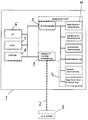
- the drawing shows the block diagram of a control and monitoring device 1 for an emergency light, which is connected to a substation 3 via a data line 2.
- the control and monitoring device 1 contains an application-specific circuit 4, that is to say a so-called ASIC, which is connected via a microprocessor interface 5 to a microprocessor 6, a permanent memory 7 and an erasable and programmable memory 8.
- the application-specific circuit 4 has an interface circuit 9 for connecting the control and monitoring device 1 to the data line 2.
- the interface circuit 9 can also contain devices for addressing luminaires.
- the application-specific circuit 4 can contain several functional units, such as a mains emergency light switchover, a control device for an inverter, a lamp monitor, a charger control, a battery monitor and clock generator and watchdog devices.
- a ROM is preferably used as the permanent memory 7 and an EEPROM as the erasable and programmable memory 8. It is also possible to use an OTP (One Time Programmable ROM) instead of a ROM. An OTP can also be used instead of an EEPROM as the memory 8, but only a one-time programming process is possible, that is to say the advantages sought with the invention cannot be fully achieved.
- OTP One Time Programmable ROM
Landscapes
- Engineering & Computer Science (AREA)
- Power Engineering (AREA)
- Business, Economics & Management (AREA)
- Emergency Management (AREA)
- Circuit Arrangement For Electric Light Sources In General (AREA)
- Non-Portable Lighting Devices Or Systems Thereof (AREA)
- Alarm Systems (AREA)
Abstract
Description
- Die Erfindung bezieht sich auf eine Steuerungs- und Überwachungseinrichtung für eine Notleuchte, die als autarke Batterie-Notleuchte oder in einem Notlichtsystem in Verbindung mit einer Unter- oder Zentralstation betrieben werden kann.
- Aus der Druckschrift ABB CEAG Katalog Einzelbatterie-Systeme gemäß VDE 0108 von 10/89 ist ein Notlichtsystem bekannt, das sogenannte Einzelbatterie-Notleuchten enthält, die autark oder in Verbindung mit einer Unterstation arbeiten können. Die bekannte Not- oder Sicherheitsleuchte wird als Einzelbatterieleuchte bezeichnet, weil sie eine eigene Batterie für den Notbetrieb enthält, also nicht aus einer Sammelbatterie gespeist wird. Da sich die Erfindung allgemein auf die Steuerungseinrichtung einer Notleuchte bezieht, ist sie jedoch nicht auf eine bestimmte Art der Stromversorgung der Leuchte beschränkt.
- Die bekannte Einzelbatterie-Notleuchte enthält eine Steuerungs- und Überwachungseinrichtung, mit deren Hilfe z.B. die nach VDE 0108 vorgesehenen wöchentlichen Funktionstest und jährlichen Betriebsdauertests, sowie eine Überwachung der Ladeeinrichtung und des Leuchtmittels programmgesteuert durchgeführt werden können. Diese Funktionen werden von einem maskenprogrammierten Mikroprozessor gesteuert. Zur Steuerungs- und Überwachungseinrichtung gehört auch ein Interface, mit dessen Hilfe der Mikroprozessor über eine Datenleitung Informationen mit einer zentralen Überwachungsstation austauschen kann. Es besteht dadurch die Möglichkeit, Betriebszustände der einzelnen an die Überwachungsstation angeschlossenen Leuchten an einem zentralen Ort anzuzeigen. An diesem Ort läßt sich auch ein Funktions- oder Betriebsdauertest auslösen und das Testergebnis anzeigen.
- Alle Funktionen, die die Notleuchte autark oder in Verbindung mit einer Zentral- oder Unterstation ausführen können soll, müssen in der Entwicklungsphase des Systems festgelegt werden. Software-Änderungen, die aufgrund kundenspezifischer Vorgaben zu irgendeinem späteren Zeitpunkt erforderlich werden, können nur insoweit berücksichtigt werden, als sie sich auf die Unterstation, die mit einem EPROM als Programmspeicher ausgerüstet ist, beziehen. Eine Änderung der Funktion der Steuerungseinrichtung der Leuchte ist praktisch aus Kosten- und Zeitgründen nicht möglich, da sie einen neuen maskenprogrammierten Mikroprozessor erforderlich machen würde.
- Davon ausgehend liegt der Erfindung die Aufgabe zugrunde, eine Steuerungseinrichtung für Notleuchten anzugeben, die eine verbesserte Anpassungsfähigkeit und nachträgliche Änderbarkeit aufweist.
- Diese Aufgabe wird gelöst durch eine Steuerungs- und Überwachungseinrichtung für eine Notleuchte, die als autarke Batterie-Notleuchte oder in einem Notlichtsystem in Verbindung mit einer Unter- oder Zentralstation betrieben werden kann, wobei die Steuerungs und Überwachungseinrichtung eine Kombination nachstehender Komponenten enthält:
- a) einen anwendungsspezifischen Schaltkreis mit für die Notleuchtensteuerung geeigneten Funktionseinheiten, wie z.B. Treiberstufen, A/D-Wandler, Umschalteinrichtungen, Taktgeber, Modulatoren und Schnittstelleneinrichtungen,
- b) einen Mikroprozessor zur programmgesteuerten Durchführung von Steuerungs- und Überwachungsfunktionen,
- c) einen Festspeicher mit wahlfreiem Zugriff, z.B. ein PROM oder OTP, in dem Dienstprogramme, z.B. Ladeprogramme für zusätzliche optionale Steuerungsfunktionen, sowie Mindest- oder Standardfunktionen zur Notleuchtensteuerung und Überwachung gespeichert sind, und
- d) einen nichtflüchtigen, lösch- und programmierbaren Speicher, insbesondere ein EEPROM, in dem zusätzliche, im speziellen Anwendungsfall benötigte Steuerungs- und Überwachungsfunktionen gespeichert sind, die zu einem beliebigen Zeitpunkt ergänzt oder geändert werden können.
- Die mit der Erfindung vorgeschlagene Aufteilung der Gesamtfunktion der Steuerungs- und Überwachungseinrichtung einer Notleuchte in einen anwendungsspezifischen Schaltkreis, einen Mikroprozessor, einen Festspeicher und einen lösch- und programmierbaren Speicher hat den Vorteil, daß eine Reihe von Grund- und Zusatzfunktionen in einen anwendungsspezifischen Schaltkreis kostengünstig realisiert werden können. Diese Funktionen können durch einen Mikroprozessor gesteuert aktiviert werden, wobei Standard-Steuerfunktionen in einem ROM gespeichert sind. Die wünschenswerte Anpassungs- und Änderungsfähigkeit wird durch den zusätzlichen lösch- und programmierbaren Speicher, z.B. ein EEPROM erreicht. Da Standard-Funktionen im Festspeicher gespeichert sind, muß der lösch- und programmierbare Speicher bei der Auslieferung nicht unbedingt programmiert sein, so daß eine sogenannte Low Cost Version möglich ist, die trotzdem die Option enthält, zu einem späteren Zeitpunkt zusätzliche Funktionen zu implementieren, parametrisieren oder zu aktivieren.
- Weitere Vorteile und Ausgestaltungsmöglichkeiten ergeben sich aus der nachstehenden Beschreibung eines Ausführungsbeispiels, das anhand der Zeichnung erläutert wird.
- In der Zeichnung ist das Blockschema einer Steuerungs- und Überwachungseinrichtung 1 für eine Notleuchte dargestellt, die über eine Datenleitung 2 mit einer Unterstation 3 verbunden ist. Die Steuerungs- und Überwachungseinrichtung 1 enthält einen anwendungsspezifischen Schaltkreis 4, also einen sogenannten ASIC, der über eine Mikroprozessor-Schnittstelle 5 mit einem Mikroprozessor 6, einem Festspeicher 7 und einem lösch- und programmierbaren Speicher 8 verbunden ist.
- Im dargestellten Beispiel ist mit gestrichelten Linien angedeutet, daß die Komponenten 6 bis 8 in einem Halbleiterbaustein integriert sein können. Es kann sich jedoch auch um einzelne Bausteine handeln. Die Komponenten 6 bis 8 können auch im anwendungsspezifischen Schaltkreis enthalten sein. Der anwendungsspezifische Schaltkreis 4 verfügt über eine Interface-Schaltung 9 zur Verbindung der Steuer- und Überwachungseinrichtung 1 mit der Datenleitung 2. Die Interface-Schaltung 9 kann auch Einrichtungen zur Leuchtenadressierung enthalten. Der anwendungsspezifische Schaltkreis 4 kann mehrere Funktionseinheiten enthalten, wie z.B. eine Netz-Notlicht-Umschaltung, eine Steuereinrichtung für einen Wechselrichter, eine Leuchtmittel-Überwachung, eine Ladeteilsteuerung, eine Batterieüberwachung und Taktgeber sowie Watch-dog-Einrichtungen.
- Als Festspeicher 7 wird vorzugsweise ein ROM und als lösch- und programmierbarer Speicher 8 ein EEPROM verwendet. Es ist auch möglich, ein OTP (One Time Programmable ROM) anstelle eines ROM's einzusetzen. Ein OTP kann zwar auch anstelle eines EEPROMs als Speicher 8 verwendet werden, wobei jedoch nur ein einmaliger Programmiervorgang möglich ist, also die mit der Erfindung angestrebten Vorteile nicht im vollen Umfang erreicht werden.
Claims (4)
- Steuerungs- und Überwachungseinrichtung für eine Notleuchte, die als autarke Batterie-Notleuchte oder in einem Notlichtsystem in Verbindung mit einer Unter- oder Zentralstation betrieben werden kann, dadurch gekennzeichnet, daß die Steuerungs- und Überwachungseinrichtung eine Kombination nachstehender Komponenten enthält:a) einen anwendungsspezifischen Schaltkreis (4) mit für die Notleuchtensteuerung geeigneten Funktionseinheiten, wie z.B. Treiberstufen, A/D-Wandler, Umschalteinrichtungen, Taktgeber, Modulatoren und Schnittstelleneinrichtungen,b) einen Mikroprozessor (6) zur programmgesteuerten Durchführung von Steuerungs- und Überwachungsfunktionen,c) einen Festspeicher mit wahlfreiem Zugriff (7), z.B. ein PROM oder OTP, in dem Dienstprogramme, z.B. Ladeprogramme für zusätzliche Steuerungsfunktionen, sowie Mindest- oder Standardfunktionen zur Notleuchtensteuerung und Überwachung gespeichert sind, undd) einen nichtflüchtigen, lösch- und programmierbaren Speicher (8), insbesondere ein EEPROM, in dem zusätzliche, im speziellen Anwendungsfall benötigte Steuerungs- und Überwachungsfunktionen gespeichert sind, die zu einem beliebigen Zeitpunkt ergänzt oder geändert werden können.
- Steuerungs- und Überwachungseinrichtung nach Anspruch 1, dadurch gekennzeichnet, daß der Mikroprozessor (6) ein Teil des anwendungsspezifischen Schaltkreises (4) ist.
- Steuerungs- und Überwachungseinrichtung nach Anspruch 1 oder 2, dadurch gekennzeichnet, daß der Festspeicher (7) ein Teil des Mikroprozessors (6) oder des anwendungsspezifischen Schaltkreises (4) ist.
- Steuerungs- und Überwachungseinrichtung nach einem der vorstehenden Ansprüche, dadurch gekennzeichnet, daß der lösch- und programmierbare Speicher (8) im anwendungsspezifischen Schaltkreis (4) integriert ist.
Applications Claiming Priority (2)
| Application Number | Priority Date | Filing Date | Title |
|---|---|---|---|
| DE4134298A DE4134298A1 (de) | 1991-10-17 | 1991-10-17 | Steuerungs- und ueberwachungseinrichtung fuer eine notleuchte |
| DE4134298 | 1991-10-17 |
Publications (3)
| Publication Number | Publication Date |
|---|---|
| EP0537651A2 true EP0537651A2 (de) | 1993-04-21 |
| EP0537651A3 EP0537651A3 (en) | 1993-05-19 |
| EP0537651B1 EP0537651B1 (de) | 1996-04-24 |
Family
ID=6442836
Family Applications (1)
| Application Number | Title | Priority Date | Filing Date |
|---|---|---|---|
| EP92117351A Expired - Lifetime EP0537651B1 (de) | 1991-10-17 | 1992-10-10 | Steuerungs- und Überwachungseinrichtung für eine Notleuchte |
Country Status (3)
| Country | Link |
|---|---|
| EP (1) | EP0537651B1 (de) |
| AT (1) | ATE137381T1 (de) |
| DE (2) | DE4134298A1 (de) |
Cited By (8)
| Publication number | Priority date | Publication date | Assignee | Title |
|---|---|---|---|---|
| WO1999060826A1 (en) * | 1998-05-15 | 1999-11-25 | Noontek Limited | Lamp fault detection |
| WO2000049700A1 (de) * | 1999-02-18 | 2000-08-24 | Ceag Sicherheitstechnik Gmbh | Notlichtsystem |
| EP1035628A1 (de) * | 1999-02-27 | 2000-09-13 | Emergi-lite safety Systems Ltd | Verbesserungen die Notbeleuchtungen und die Installationen betreffen |
| EP2280493A2 (de) | 2009-06-18 | 2011-02-02 | RP-Technik e. K. | Sicherheitsbezogenes Kommunikationsverfahren auf Energieversorgungsleitungen und ein dazugehöriges Netz |
| AT13873U1 (de) * | 2013-04-30 | 2014-10-15 | Tridonic Gmbh & Co Kg | Verfahren zur Ansteuerung von Leuchtmittelbetriebsgeräten |
| AT14562U1 (de) * | 2014-03-26 | 2016-01-15 | Tridonic Gmbh & Co Kg | Vorrichtungen, Systeme und Verfahren für einen Notlichtbetrieb |
| WO2017089051A1 (de) * | 2015-11-27 | 2017-06-01 | Eaton Protection Systems Ip Gmbh & Co. Kg | Zyklustestverfahren |
| US10122206B2 (en) | 2014-03-26 | 2018-11-06 | Tridonic Gmbh & Co Kg | Devices, systems and methods for emergency light operation |
Families Citing this family (6)
| Publication number | Priority date | Publication date | Assignee | Title |
|---|---|---|---|---|
| DE4318364A1 (de) * | 1993-05-28 | 1994-12-01 | Siemens Ag | Verfahren und Schaltungsanordnung zur Funktionsüberwachung von Beleuchtungseinrichtungen |
| DE19501582A1 (de) * | 1995-01-20 | 1996-07-25 | Aeg Ews Stromversorgungen Soer | Schaltungsanordnung zum Überwachen und Steuern einer Sicherheitsbeleuchtungsanlage |
| DE19807844C5 (de) * | 1998-02-25 | 2006-08-03 | Inotec Sicherheitstechnik Gmbh | Einrichtung zur zentralen Notlichtversorgung |
| ITMI981110A1 (it) * | 1998-05-20 | 1999-11-20 | Beghelli Spa | Sistema elettronico di controllo del funzionamento di lampade per l'illuminazione di emergenza |
| DE10212064B4 (de) | 2002-03-19 | 2008-08-21 | Robert Bosch Gmbh | Betriebssteuerung für eine Handwerkzeugmaschine |
| DE20205234U1 (de) * | 2002-04-04 | 2003-08-14 | CEAG Sicherheitstechnik GmbH, 59494 Soest | Leuchte |
Family Cites Families (3)
| Publication number | Priority date | Publication date | Assignee | Title |
|---|---|---|---|---|
| IT1213713B (it) * | 1987-10-29 | 1989-12-29 | Monteveglio Bo A | Sistema di illuminazione autonoma di emergenza con autodiagnosi di funzionamento programmata,visualizzata ed eventualmente centralizzata unitamente alla alimentazione di carica elettrica |
| US4977353A (en) * | 1989-08-31 | 1990-12-11 | Minitronics Pty Limited | Communication system for single point emergency lighting |
| DE4002485C1 (en) * | 1990-01-29 | 1991-08-01 | Mathias Dipl.-Ing. 8000 Muenchen De Hoermann | Protecting LV lighting systems independently of load - using comparator, timer, max. power adjuster and recorder for amt. of dimming |
-
1991
- 1991-10-17 DE DE4134298A patent/DE4134298A1/de not_active Ceased
-
1992
- 1992-10-10 AT AT92117351T patent/ATE137381T1/de active
- 1992-10-10 DE DE59206105T patent/DE59206105D1/de not_active Expired - Lifetime
- 1992-10-10 EP EP92117351A patent/EP0537651B1/de not_active Expired - Lifetime
Cited By (10)
| Publication number | Priority date | Publication date | Assignee | Title |
|---|---|---|---|---|
| WO1999060826A1 (en) * | 1998-05-15 | 1999-11-25 | Noontek Limited | Lamp fault detection |
| US6396216B1 (en) | 1998-05-15 | 2002-05-28 | Noontek Limited | Lamp fault detection |
| WO2000049700A1 (de) * | 1999-02-18 | 2000-08-24 | Ceag Sicherheitstechnik Gmbh | Notlichtsystem |
| EP1035628A1 (de) * | 1999-02-27 | 2000-09-13 | Emergi-lite safety Systems Ltd | Verbesserungen die Notbeleuchtungen und die Installationen betreffen |
| EP2280493A2 (de) | 2009-06-18 | 2011-02-02 | RP-Technik e. K. | Sicherheitsbezogenes Kommunikationsverfahren auf Energieversorgungsleitungen und ein dazugehöriges Netz |
| AT13873U1 (de) * | 2013-04-30 | 2014-10-15 | Tridonic Gmbh & Co Kg | Verfahren zur Ansteuerung von Leuchtmittelbetriebsgeräten |
| AT14562U1 (de) * | 2014-03-26 | 2016-01-15 | Tridonic Gmbh & Co Kg | Vorrichtungen, Systeme und Verfahren für einen Notlichtbetrieb |
| US10122206B2 (en) | 2014-03-26 | 2018-11-06 | Tridonic Gmbh & Co Kg | Devices, systems and methods for emergency light operation |
| WO2017089051A1 (de) * | 2015-11-27 | 2017-06-01 | Eaton Protection Systems Ip Gmbh & Co. Kg | Zyklustestverfahren |
| US10983169B2 (en) | 2015-11-27 | 2021-04-20 | Eaton Intelligent Power Limited | Cycle test method |
Also Published As
| Publication number | Publication date |
|---|---|
| EP0537651B1 (de) | 1996-04-24 |
| EP0537651A3 (en) | 1993-05-19 |
| DE4134298A1 (de) | 1993-04-22 |
| DE59206105D1 (de) | 1996-05-30 |
| ATE137381T1 (de) | 1996-05-15 |
Similar Documents
| Publication | Publication Date | Title |
|---|---|---|
| EP0537651B1 (de) | Steuerungs- und Überwachungseinrichtung für eine Notleuchte | |
| DE69508964T2 (de) | Benutzerdefinierte schnittstelle und protokollschema für eine speicherprogrammierbare steuerung | |
| DE3836644C2 (de) | Unabhängiges Notbeleuchtungs-System mit Selbstdiagnose | |
| US6104971A (en) | Controller, in particular motor vehicle controller | |
| DE3017299A1 (de) | Nichtzentrales rechnersteuerungssystem | |
| DE68915792T2 (de) | Schutzvorrichtung für Regler mit Mikro-Rechner. | |
| EP1174781A2 (de) | Einrichtung zur Signalübertragung | |
| DE4440127A1 (de) | Steuergerät | |
| DE69419861T2 (de) | Elektronisches steuergerät | |
| DE3018275C2 (de) | ||
| DE3787226T2 (de) | Festspeichersteuerung. | |
| EP1513376A1 (de) | Beleuchtungssystem | |
| EP0950935B1 (de) | Vorrichtung zur Steuerung einer Mehrzahl von Beleuchtungselementen | |
| DE102012107216B4 (de) | Elektrischer/elektronischer Aktor | |
| EP0376983B1 (de) | Universalsteuergerät für regeleinrichtungen | |
| DE102010033039A1 (de) | Verfahren zum Bereitstellen von Sicherheitsfunktionen | |
| WO1999006895A1 (de) | Schaltungsanordnung und verfahren zur speicherplatzverwaltung und zur abarbeitung von anwenderprogrammen in kleinsteuerungen | |
| DE102006035889A1 (de) | System und Verfahren zur automatischen Installation und Wartung von Hard- und Software in einem verteilten Computersystem | |
| DE19645626A1 (de) | Ein/Ausgabeverfahren und -einrichtung für ein Bussystem der Gebäudesystemtechnik | |
| DE69616120T2 (de) | Empfangs-Verwaltungssystem für von elektronischen Vorrichtungen stammende digitale Signale, die fähig sind, die Melderkonfiguration zu lernen, insbesondere für Alarmsysteme | |
| DE19838469B4 (de) | Prozeßsteuer- und Regelsystem mit verteilter Verarbeitung | |
| EP0642090B1 (de) | Elektronische Baugruppe mit wenigstens einer dezentralen Prozessoreinrichtung eines mehrprozessorgesteuerten Systems | |
| EP0669027B1 (de) | Anordnung zur adressierung von peripheren einheiten | |
| DE19710286C1 (de) | Steuereinheit für Kabinensysteme von Luftfahrzeugen | |
| DE19935235C1 (de) | Extern programmierbares elektronisches Regel- und Steuergerät |
Legal Events
| Date | Code | Title | Description |
|---|---|---|---|
| PUAI | Public reference made under article 153(3) epc to a published international application that has entered the european phase |
Free format text: ORIGINAL CODE: 0009012 |
|
| PUAL | Search report despatched |
Free format text: ORIGINAL CODE: 0009013 |
|
| AK | Designated contracting states |
Kind code of ref document: A2 Designated state(s): AT BE DE FR GB IT NL |
|
| AK | Designated contracting states |
Kind code of ref document: A3 Designated state(s): AT BE DE FR GB IT NL |
|
| 17P | Request for examination filed |
Effective date: 19930617 |
|
| 17Q | First examination report despatched |
Effective date: 19950222 |
|
| GRAH | Despatch of communication of intention to grant a patent |
Free format text: ORIGINAL CODE: EPIDOS IGRA |
|
| GRAA | (expected) grant |
Free format text: ORIGINAL CODE: 0009210 |
|
| ITPR | It: changes in ownership of a european patent |
Owner name: C.NE EPO REG. 20;CEAG SICHERHEITSTECHNIK GMBH |
|
| AK | Designated contracting states |
Kind code of ref document: B1 Designated state(s): AT BE DE FR GB IT NL |
|
| REF | Corresponds to: |
Ref document number: 137381 Country of ref document: AT Date of ref document: 19960515 Kind code of ref document: T |
|
| REF | Corresponds to: |
Ref document number: 59206105 Country of ref document: DE Date of ref document: 19960530 |
|
| ET | Fr: translation filed | ||
| RAP2 | Party data changed (patent owner data changed or rights of a patent transferred) |
Owner name: CEAG SICHERHEITSTECHNIK GMBH |
|
| GBT | Gb: translation of ep patent filed (gb section 77(6)(a)/1977) |
Effective date: 19960531 |
|
| ITF | It: translation for a ep patent filed | ||
| NLT2 | Nl: modifications (of names), taken from the european patent patent bulletin |
Owner name: CEAG SICHERHEITSTECHNIK GMBH |
|
| NLXE | Nl: other communications concerning ep-patents (part 3 heading xe) |
Free format text: PAT.BUL.08/96 PAGE 1100: CORR.: CEAG SICHERHEITSTECHNIK GMBH. |
|
| PLBE | No opposition filed within time limit |
Free format text: ORIGINAL CODE: 0009261 |
|
| 26N | No opposition filed | ||
| REG | Reference to a national code |
Ref country code: GB Ref legal event code: IF02 |
|
| NLS | Nl: assignments of ep-patents |
Owner name: CEAG SICHERHEITSTECHNIK GMBH |
|
| REG | Reference to a national code |
Ref country code: GB Ref legal event code: 732E |
|
| BECH | Be: change of holder |
Owner name: *CEAG NOTLICHTSYSTEME G.M.B.H. Effective date: 20040702 |
|
| NLT1 | Nl: modifications of names registered in virtue of documents presented to the patent office pursuant to art. 16 a, paragraph 1 |
Owner name: COOPER CROUSE-HINDS GMBH |
|
| REG | Reference to a national code |
Ref country code: FR Ref legal event code: TP |
|
| PGFP | Annual fee paid to national office [announced via postgrant information from national office to epo] |
Ref country code: NL Payment date: 20091009 Year of fee payment: 18 |
|
| PGFP | Annual fee paid to national office [announced via postgrant information from national office to epo] |
Ref country code: IT Payment date: 20091013 Year of fee payment: 18 Ref country code: FR Payment date: 20091020 Year of fee payment: 18 |
|
| PGFP | Annual fee paid to national office [announced via postgrant information from national office to epo] |
Ref country code: BE Payment date: 20091118 Year of fee payment: 18 |
|
| PGFP | Annual fee paid to national office [announced via postgrant information from national office to epo] |
Ref country code: AT Payment date: 20100923 Year of fee payment: 19 |
|
| PGFP | Annual fee paid to national office [announced via postgrant information from national office to epo] |
Ref country code: DE Payment date: 20101029 Year of fee payment: 19 |
|
| BERE | Be: lapsed |
Owner name: *CEAG NOTLICHTSYSTEME G.M.B.H. Effective date: 20101031 |
|
| REG | Reference to a national code |
Ref country code: NL Ref legal event code: V1 Effective date: 20110501 |
|
| PG25 | Lapsed in a contracting state [announced via postgrant information from national office to epo] |
Ref country code: FR Free format text: LAPSE BECAUSE OF NON-PAYMENT OF DUE FEES Effective date: 20101102 |
|
| REG | Reference to a national code |
Ref country code: FR Ref legal event code: ST Effective date: 20110630 |
|
| PG25 | Lapsed in a contracting state [announced via postgrant information from national office to epo] |
Ref country code: BE Free format text: LAPSE BECAUSE OF NON-PAYMENT OF DUE FEES Effective date: 20101031 Ref country code: NL Free format text: LAPSE BECAUSE OF NON-PAYMENT OF DUE FEES Effective date: 20110501 |
|
| PGFP | Annual fee paid to national office [announced via postgrant information from national office to epo] |
Ref country code: GB Payment date: 20110930 Year of fee payment: 20 |
|
| PG25 | Lapsed in a contracting state [announced via postgrant information from national office to epo] |
Ref country code: IT Free format text: LAPSE BECAUSE OF NON-PAYMENT OF DUE FEES Effective date: 20101010 |
|
| REG | Reference to a national code |
Ref country code: DE Ref legal event code: R071 Ref document number: 59206105 Country of ref document: DE |
|
| REG | Reference to a national code |
Ref country code: DE Ref legal event code: R071 Ref document number: 59206105 Country of ref document: DE |
|
| REG | Reference to a national code |
Ref country code: GB Ref legal event code: PE20 Expiry date: 20121009 |
|
| REG | Reference to a national code |
Ref country code: AT Ref legal event code: MK07 Ref document number: 137381 Country of ref document: AT Kind code of ref document: T Effective date: 20121010 |
|
| PG25 | Lapsed in a contracting state [announced via postgrant information from national office to epo] |
Ref country code: GB Free format text: LAPSE BECAUSE OF EXPIRATION OF PROTECTION Effective date: 20121009 |