EP0537679A2 - Antriebsmechanismus für Drucker - Google Patents
Antriebsmechanismus für Drucker Download PDFInfo
- Publication number
- EP0537679A2 EP0537679A2 EP92117459A EP92117459A EP0537679A2 EP 0537679 A2 EP0537679 A2 EP 0537679A2 EP 92117459 A EP92117459 A EP 92117459A EP 92117459 A EP92117459 A EP 92117459A EP 0537679 A2 EP0537679 A2 EP 0537679A2
- Authority
- EP
- European Patent Office
- Prior art keywords
- cam
- motor
- paper feed
- printer
- print head
- Prior art date
- Legal status (The legal status is an assumption and is not a legal conclusion. Google has not performed a legal analysis and makes no representation as to the accuracy of the status listed.)
- Granted
Links
Images


Classifications
-
- B—PERFORMING OPERATIONS; TRANSPORTING
- B41—PRINTING; LINING MACHINES; TYPEWRITERS; STAMPS
- B41J—TYPEWRITERS; SELECTIVE PRINTING MECHANISMS, i.e. MECHANISMS PRINTING OTHERWISE THAN FROM A FORME; CORRECTION OF TYPOGRAPHICAL ERRORS
- B41J23/00—Power drives for actions or mechanisms
- B41J23/02—Mechanical power drives
- B41J23/025—Mechanical power drives using a single or common power source for two or more functions
Definitions
- the present invention relates to serial printers that print characters and graphics while moving a print head in a line direction across a recording paper. More particularly, the invention relates to a paper feed mechanism for feeding recording paper in such printers and to the control of the paper feed mechanism.
- a prior art serial printer known as two-motor printer employs a first motor as the drive source for reciprocating a carriage on which the print head is mounted, and an independent second motor as the drive source for feeding the recording paper. Since with such two-motor printer the two motors are controlled separately, the stroke of the carriage can be freely selected depending on the length of the lines to be printed, and the paper feed can be performed without being affected by the operation of the carriage. On the other hand, controlling of the two motors must be made in a synchronized manner. This requires complicated control means resulting in increased manufacturing costs and a difficulty to make the printer compact and lightweight.
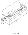
- the document JP-A-50715/1991 discloses a prior art serial printer that uses a single motor for both, as drive source for the print head and drive source for feeding the recording paper. This known printer will be explained in more detail with reference to Figs. 14 and 15.
- the printer 1 has a thermal type print head 4 slidably supported on a main guide shaft 7 and driven by means of a cam shaft 3 having a helical cam profile 2 formed thereon.
- a cam shaft 3 having a helical cam profile 2 formed thereon.
- cam profile 2 formed thereon.
- cam profile 2 formed thereon.
- Groove-shaped cam profiles 5 and 6 (referred to as cam grooves in the following) that form part of a paper feed mechanism are provided in the main guide shaft 7.
- a pin mounted on the print head 4 and serving as a cam follower engages the cam groove 5 or 6, thus causing the main guide shaft 7 to rotate.
- This rotation is transmitted to a paper feed shaft (not shown) by means of a gear 7a fixed to guide shaft 7, a sector gear 8a freely rotatable on the paper feed shaft, and a one-way clutch connecting the sector gear 8a and the paper feed shaft.
- the one way clutch comprises a ratchet portion on the outward facing end face of sector gear 8a as the drive part and a clutch wheel 8 as the driven part.
- the clutch wheel 8 is fixed to the paper feed shaft and has a ratchet portion to engage that of the sector gear 8a.
- Sector gear 8a is movable along the paper feed shaft and urged by spring means (not shown) into engagement with clutch wheel 8.
- the ratchet portions of sector gear 8a and clutch wheel 8 are such as to transfer a rotation of the sector gear 8a in one direction to the clutch wheel and thus the paper feed shaft but to slide upon each other with no transfer of rotation when the sector gear 8a rotates in a direction opposite to said one direction.
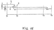
- Fig. 15 is a diagram showing cam grooves 5 and 6 in developed form as lines 5 and 6.
- the abscissa corresponds to the axial direction of main guide shaft 7 and the ordinate to the circumferential direction.
- the two cam grooves 5 and 6 have different angles of rotation ⁇ 1 and ⁇ 2, respectively. They are connected by a connection groove 9 between Q1 and Q2 and merge to a common groove portion at a junction between Q3 and Q4.
- the print head reciprocates in the range from the left end Q1 to the position Q3 on the right side.
- the print head 4 reciprocates in the range from the left end Q1 to the right end Q4.
- the one-way clutch ensures that a rotation of the main guide shaft 7 in only one of the two opposite directions results in paper being actually fed.
- a rotation of the main guide shaft caused by the print head moving from the left side in Fig. 15 to the right side will not be transmitted by the one-way clutch while a rotation in the opposite direction will be transmitted.
- the cam follower engages either cam groove 5 or 6 depending on the printing mode that was selected when the print head returned to its home position. If it is cam groove 5, the main guide shaft will be turned as the print head moves to Q2 but this rotation will not be transmitted by the one-way clutch.
- the print head starts at Q1 with its cam follower engaging cam groove 6, as the print head moves to Q2 the cam follower will change to cam groove 5 via the shallow connection groove 9.
- the print head moves up to position Q3 and then returns so that the cam follower will stay in cam groove 5.
- the print head moves from Q2 to Q1 on its way back the main guide shaft 7 is rotated by the angle ⁇ 1 and the paper is fed by a corresponding amount.
- the print head moves up to position Q4 before it returns.
- this prior art printer uses the same single motor as the power source for both, moving the print head 4 and feeding paper, it can be realized as a compact, lightweight printer.
- the accuracy of paper feed is low.
- External forces due to fluctuations in friction between the cam follower pin and the cam grooves are transmitted directly to the print head and affect the speed of the print head, thus degrading print quality.
- the necessity of machining a cam groove in the long, cylindrical main guide shaft requires more time for machining parts and makes it difficult to lower manufacturing costs.
- the one-way clutch uses a drive ratchet member and a driven ratchet member continuously pressed against each other by means of a spring.
- Such clutch generates a disturbing noise when the drive member is rotated in a direction in which ratchet teeth of the drive member and the driven member, respectively, slide upon each other and no torque is being transmitted. Furthermore, in the one-way clutch the spring force urging the drive member against the driven member is very critical. If it is too weak rotation may be not or not sufficiently transmitted. If it is too strong, sometimes a rotation in a direction in which the clutch should be disengaged may be transmitted. Thus, the accuracy of paper feed and by that the printing quality in this prior art is not very high.
- the invention is intended to solve these problems and its purpose is to provide a lightweight, compact, highly reliable printer that is capable of performing high quality printing.
- the accuracy of the paper feed can be substantially improved since whether or not torque is transmitted does no longer depend on the friction between two clutch members as in the prior art.
- the generation of disturbing noise that unavoidably occurs in the prior art can be easily prevented.
- a belt drive mechanism for driving the carriage is useful to prevent interaction between the carriage and the paper feed mechanism and, thereby to further improve the print quality, when the linkage between the rotary member and the motor is arranged not to include the carriage.
- the elasticity and flexibility of a belt absorbs any vibration that might be caused by the paper feed mechanism. Such vibration is, therefore, not transmitted to the carriage. Also, when the carriage is not used to drive a cam as in the prior art mentioned above, it can smoothly slide along its guide shaft unaffected by the paper feed function.
- the drive force for the rotary member can be advantageously derived from a second cam mechanism and gear means connecting a cam means of said second cam mechanism directly to the motor. If the cam means of such second cam mechanism has two or more cam profile portions that can be selectively traced by a corresponding cam follower the paper feed amount or line spacing of the printer can be easily controlled. Selection between the cam profile portions may for instance be achieved by controlling the stroke of the reciprocating movement of the cam means or the stroke of the reciprocating movement of the carriage if it is synchronous with that of the cam means.
- the prior art printer explained above has a structure of cam grooves that allow the amount of paper feed, i.e. the line spacing to be switched between two different values for the character mode and the graphics mode, respectively. Further, this structure provides a fast paper feed function by having the print head 4 reciprocating between positions Q1 and Q2. Apart from increased manufacturing costs involved in machining the main guide shaft of this prior art printer, switching among various paper feed modes is possible at the expense of a degraded print quality only. As will be better understood from the following detailed description of embodiments of the invention the first cam mechanism according to the invention allows to realize such switching between several paper feed modes in a way that does not only require less manufacturing costs but also ensures a high quality of printing.
- the printer structure according to the present invention is especially suitable for small sized compact printers as they are commonly used as built-in units of table-top or hand-held devices and which have a base area of for instance 12 x 9 cm and a height of for instance 5 cm.
- the printer has a base 30, a print head 11 and a platen 21.
- the print head 11 is mounted on a carriage 12 slidably supported by a main guide shaft 13.
- the main guide shaft 13 is fixed to the base 30.
- Recording paper 20 is inserted between the print head 11 and the platen 21 to be printed by the print head 11.
- the print head 11 may be a dot matrix print head, for instance an ink jet print head that prints in response to signals input via a printed wiring 14, and is capable of both, a character mode for printing characters and a graphics mode for printing graphics.
- the printer of this embodiment utilizes a belt drive system for driving the carriage 12 and the print head 11 along the main guide shaft 13 in parallel to the platen 21 and the recording paper 20, i.e. to the left and right directions of the base 30 as indicated by an arrow in Fig. 1.
- the belt drive system comprises a timing belt 22 having formed gear teeth on its inner surface and being secured to the carriage 12. A portion of the timing belt 22 is guided by means of two pulleys 23a and 23b to extend in parallel to the main guide shaft 13.
- the timing belt 22 engages a belt gear 22 which in turn meshes with a belt drive gear 25 provided on the shaft of a motor not shown.
- the belt gear 24 and the belt drive gear 25 are disposed on the base 30 at one corner thereof opposite to the main guide shaft 13.
- the belt drive gear 25 is positioned adjacent to the platen 21.
- a connector 31 for supplying signals to the motor which serves as the drive source for the belt drive gear 25 is provided in the same area of the base 30.
- the platen 21 is part of a platen cover 28 detachably provided on a paper guide unit 26 which is fixed to or integral part of the base 30.
- Figs. 2 and 3 show the printer with the platen cover 28 removed from the paper guide unit 26 so that a paper feed shaft 90 and a paper feed roller 29 supported by the paper guide unit 26 are visible.
- the paper feed shaft 90 which drives the paper feed roller 29, is supported in shaft holes 27a and 27b formed in side walls 26a and 26b of paper guide unit 26.
- the paper feed shaft 90 is driven via a clutch 50, a paper feed lever 60, a paper feed control member 40 and the belt drive gear 25 by means of the same motor that is used to drive the carriage 12 as will be described in more detail later.
- a home position sensor 32 is mounted on the base 30 at the right front corner thereof. Sensor 32 cooperates with a protrusion 12a on the carriage 12 to detect the home or reference position of the print head 11 or a reference position of the motor, whenever the protrusion 12a enters the home position sensor 32.
- the paper feed control member 40 has a cylindrical or disc shape and is rotatably supported on a shaft 48 fixed on a base plate 49 as shown in Figs. 3, 4 and 5.
- the base plate 49 is mounted to the side wall 26a of the paper guide unit 26 facing the belt drive gear 25.
- the paper feed control member 40 On its end face opposite to the base plate 49 the paper feed control member 40 has formed a bevel gear 41 meshing with a bevel gear 25a integrally formed on the upward facing end face of the belt drive gear 25. That is, the rotational axes of the belt drive gear 25 and the paper feed control member 40 are arranged perpendicular to each other.
- a cam groove 70 is formed in the cylindrical outer circumferential face 42 of the paper feed control member 40 and a cam groove 80 is formed in the rear end face 43 of the paper feed control member 40 facing base plate 49.
- cam groove 80 is part of a second cam mechanism and is used to impart a rotation to the paper feed shaft 90 by means of the paper feed lever 60 and in response to a rotation of the paper feed control member 40.
- the clutch 50 is provided to make or break a torque transmitting connection between paper feed lever 60 and paper feed shaft 90 and engagement and disengagement of clutch 50 are controlled by means of cam groove 70 via a clutch lever 53.
- Cam groove 70 is part of a first cam mechanism.
- the paper feed control member 40 has, thus, combined in it two cam mechanisms which, in addition to the fact of using a single motor for driving the print head and feeding the paper, facilitates to make the printer compact.
- Fig. 4 shows the paper feed mechanism in detail
- Fig. 5 shows it in an exploded view illustrating how the individual components are assembled.
- the paper feed lever 60 used to drive the paper feed shaft 90 via clutch 50 comprises as an integral unit a disc-shaped portion 64 and a lever portion 63.
- a cam follower pin 61 for engagement with cam groove 80 is mounted to the end of lever portion 63.
- a leaf spring 62 is used to elastically urge cam follower pin 61 to the bottom surface of cam groove 80 so that the cam follower pin 61 can accurately trace the cam groove 80 which has a varying depth.
- Clutch 50 comprises a drive clutch member or ratchet wheel 56 and a driven clutch member or ratchet wheel 58, the latter being mounted on or integral with paper feed shaft 90.
- Portion 64 of paper feed lever 60 has a recess 65 for accommodating ratchet wheel 56, and a shaft 66 is provided in the center of the recess 65 to serve as a support shaft for the paper feed lever 60.
- Shaft 66 is rotatably inserted into a corresponding bore in the end face of paper feed shaft 90.
- Ratchet wheel 56 is rotatably and slidably supported on an end portion of paper feed shaft 90 extending beyond ratchet wheel 58 (Fig. 4).
- the paper feed lever 60 is turned around an axis which is coaxial with the axis of paper feed shaft 90.
- the drive ratchet wheel 56 is positively engaged with the portion 64 of paper feed lever 60. Therefore, the drive ratchet wheel 56 rotates together with paper feed lever 60 in both directions.
- the clutch lever 53 controls the position of the drive ratchet wheel 56 on shaft 90 in its axial direction such as to engage ratchet wheels 56 and 58 with each other or separate them from each other.
- Each of the opposing end faces of the ratchet wheels 56 and 58 has a ring of ratchet teeth formed thereon.
- the ratchet teeth have a saw-tooth like shape and those of one ratchet wheel are inclined in a direction opposite to those of the other ratchet wheel.
- a spring 54 is disposed between the drive ratchet wheel 56 and the paper feed lever 60 to urge the drive ratchet wheel 56 against the driven ratchet wheel 58.
- An arc shaped protrusion 55 extends axially from the peripheral edge of the end face of drive ratchet wheel 56 opposite to the ratchet teeth.
- the protrusion 55 fits into a cutout formed in the wall of portion 64 of paper feed lever 60 that surrounds the recess 65, as best shown in Fig. 5.
- Another protrusion (not shown) extending radially from the periphery of the ratchet wheel 56 fits into a groove formed in the wall that surrounds the recess 65.
- This provides for a positive coupling between the paper feed lever 60 and the drive ratchet wheel 56 allowing the ratchet wheel 56 to slide axially within the recess 65 and allowing a drive force from the paper feed lever 60 to be transferred to the drive ratchet wheel 56.
- a hole 57 for inserting a connection member 53a of the clutch lever 53 is formed in this protrusion 55.
- the clutch lever 53 is rotatably supported at one end as indicated at 53b.
- the rotational axis of the clutch lever extends perpendicular to the axis of paper feed shaft 90.
- the clutch lever 53 carries a cam follower pin 51 resiliently urged by a leaf spring 52 into engagement with cam groove 70.
- clutch lever 53 is turned under the control of cam groove 70 as the paper feed control member 40 rotates.
- the spring force of leaf spring 52 keeps the cam follower pin 51 in contact with the bottom of cam groove 70 whose depth varies. Due to the engagement of the connection member 53a of the clutch lever 53 with the hole 57 in protrusion 55, the clutch 50 will be engaged and disengaged in response to a movement of the clutch lever 53 under the control of cam groove 70.
- Use of the clutch lever 53 to engage and disengage the clutch 50 as in the present embodiment avoids generation of noise that would otherwise occur when the drive ratchet wheel 56 and driven ratchet wheel 58 where rotated with respect to each other in the non-torque transmitting direction while being pressed together. Shifting of the ratchet wheel 56 away from the ratchet wheel 58 by an amount sufficient to separate the respective ratchet teeth from each other further contributes to substantially increase the accuracy of paper feed. Without such shifting, even when the drive ratchet wheel rotates in a direction in which the one-way clutch should not transmit a torque, a torque may nevertheless be transmitted if the friction between the ratchet teeth is too strong to allow them to slide upon each other. Since the friction depends on various factors such malfunctioning of the one-way clutch is hard to avoid.
- the clutch need not necessarily be a one-way clutch. Since engagement and disengagement of the clutch is controlled by means of the clutch lever 53 in this embodiment, the engaging faces of the driven ratchet wheel and the drive ratchet wheel could also be formed in a shape to allow torque transmission in both directions of rotation. Whether or not a torque actually is transmitted is controlled by means of the first cam mechanism comprising cam groove 70 and clutch lever 53 with cam follower pin 51.
- cam grooves 70 and 80 will be explained in the following with reference to Fig. 6, 7 and 8. It should be noted, that for reciprocating the carriage 12 and thus the print head 11 across the recording paper 20 the motor driving the belt drive gear 25 is repeatedly reversed, i.e. it rotates in one direction to move the print head from its home or reference position to the opposite end of its shift range, and it is rotated in the opposite direction to return the print head to its home position.
- the transmission from the belt drive gear 25 to the carriage 12 via belt gear 24 and belt 22 in this embodiment is selected such that there is a one-to-one relationship between the rotation of the belt drive gear 25 and the movement of the carriage 12.
- each angular position of the drive belt gear 25 corresponds to a unique position of the print head 11 within its range of movement.
- the paper feed control member 40 e.g. each angular position of the paper feed control member 40 within an angle of no more than 360° corresponds to a respective unique position of the print head 11.
- Fig. 6 is a plan view of the rear end surface 43 of paper feed control member 40 having the cam groove 80 formed therein.
- Fig. 7 shows cam groove 70 in a developed form
- Fig. 8 shows the positional relationship between cam grooves 70 and 80 and print head 11 as well as the varying depths of cam grooves 70 and 80.
- cam groove 80 starts at a radially inner end 81 near to the rotational axis of paper feed control member 40 and has a first portion 80a substantially concentric to said rotational axis. Cam groove 80 then extends at a relatively steep slope, i.e., nearly radially towards the outer circumference of the paper feed control member 40. At a first junction 85 the cam groove 80 separates into two cam groove portions 83 and 84 extending substantially concentric to the rotational axis of the paper feed control member 40, with cam groove portion 84 being located radially inside of cam groove portion 83.
- the two cam groove portions 83 and 84 recombine to commonly extend along a path substantially concentric to the rotational axis of paper feed control member 40 up to the outer end 82 of cam groove 80.
- the common groove portions of cam groove 80 are relatively deep.
- the depth of cam groove portion 83 at the first junction 85 is the same as the depth of the common groove portions, but beyond junction 85 the depth of cam groove portion 83 gradually decreases and then quickly returns to the initial value at the second junction 86.
- the depth of cam groove portion 84 varies in a way opposite to that of cam groove portion 83, i.e. at the first junction 85 the depth of cam groove portion 84 decreases abruptly and then starts to gradually increase beyond junction 85 to reassume the depth of the common groove portions before the second junction 86.
- cam groove 70 has a common groove portion 70a up to a first junction 75 where it divides into cam groove portions 73 and 74.
- Cam groove portions 73 and 74 extend in parallel to each other with cam groove portion 74 forming an extension of the common groove portion 70a.
- the cam groove portions 73 and 74 recombine to a common groove portion 70b of cam groove 70 up to the opposite cam groove end 72.
- Portion 70b of cam groove 70 forms an extension of cam groove portion 73, i.e., the two common groove portions 70a and 70b are displaced axially with respect to each other by the distance between cam groove portions 73 and 74.
- the cam groove 80 and the print head positions reference is made to Fig. 8.
- the depth of the cam groove portions 73 and 74 varies as indicated in Fig. 8d, i.e. with respect to the depth of the common groove portions 70a, 70b.
- Cam groove portion 73 has a depth gradually decreasing beyond junction 75 and abruptly re-increasing at junction 76, whereas cam groove portion 74 has a depth abruptly decreasing at junction 75 and then gradually re-increasing to reach the initial value at junction 76.
- selection between character mode and graphics mode is done by selecting the stroke of the print head 11.
- the print head 11 In the character mode the print head 11 is reciprocated between positions P1 and P4 shown in Fig. 8e.
- the print head is reciprocated between positions P1 and P5.
- the cam follower pin 51 has entered the deep groove portion 73 at junction 75, whereby the clutch lever 53 has been turned in a clockwise direction (in Fig. 5) to separate drive ratchet wheel 56 from driven ratchet wheel 58 and, thus, to disengage clutch 50.
- the first portion 80a of cam groove 80 immediately following the end 81 is substantially concentric to the rotational axis of paper feed control member 40 and, thus, does not cause a significant turning movement of paper feed lever 60.
- cam follower pin 51 It is only after cam follower pin 51 has entered cam groove portion 73 to disengage clutch 50, that cam follower pin 61 tracing cam groove 80 turns paper feed lever 60 in the counterclockwise direction in Fig. 5. Since clutch 50 is disengaged, no rotation is transmitted to paper feed shaft 90 at this time. At junction 85 cam follower pin 61 enters cam groove portion 83 since it is deeper than cam groove portion 84.
- the print head 11 moves from the position P2 at the right side of the recording paper 20 to the position P4 at the left side.
- the motor is reversed and print head 11 starts moving back to its position P2.
- the cam follower pin 61 does not reach junction 86 of cam groove 80 and, thus, again traces cam groove portion 83 as the print head 11 returns.
- the cam follower pin 51 enters cam groove portion 74 at junction 76, since at this point the depth of the cam groove portion 74 is larger then that of the cam groove portion 73.
- the print head 11 reciprocates between positions P1 and P5.
- the operation during the forward stroke of the print head from P1 to P4 is the same as with the character mode and, thus, need not be explained again.
- the cam follower pin 61 passes junction 86 of cam groove 80.
- the cam follower pin 61 runs into cam groove portion 84 at junction 86 since at this point the cam groove portion 84 is deeper then the cam groove portion 83.
- the cam follower pin 61 traces the cam groove portion 84 until it enters the common groove portion at junction 85.
- Fig. 9 shows a piece of recording paper 20 with a sample print-out.
- the print head 11 has a dot pattern with twelve dots arranged in a vertical row.
- the line spacing between two successive lines is achieved by feeding the recording paper 20 by twenty dots (5.2 mm) at a time under the control of cam groove portion 83.
- the paper feed amount corresponds to twelve dots (3.2 mm) so that the distance between the lowest dot of a previous line and the uppermost dot of the current line is just the same as the distance between two adjacent dots of the print head's dot pattern. In this way, two successive lines in the graphics mode are contiguous to each other without any extra space there between.
- the printer according to the present embodiment of the invention provides a fast paper feed mode which is a mode in which paper is fed but no printing performed.
- the fast paper feed mode is accomplished by reciprocating the print head 11 between the home position P1 and the fast feed position P3.
- the operation of the individual elements as the print head 11 moves from P1 to P3 is the same as in the character mode so that explanation is omitted here.
- the fast feed position P3 is past the junction 76 between cam groove portions 73 and 74 so that on return from P3 to P1, the cam follower pin 51 traces cam groove portion 74 to keep clutch 50 engaged.
- the stroke of the reciprocating print head in the fast paper feed mode is shorter and, thus, paper feed faster then in the character mode and in the graphics mode. All that has to be done for changing operation between character mode, graphics mode and fast paper feed mode is to change the stroke of the print head, i.e. the distance the print head moves from its home position to its return position, or the angle by which the motor is rotated from a reference position until it is reversed.
- the embodiment of the present invention explained so far combines the advantage of providing a character mode, a graphics mode and a fast paper feed mode with the advantage of requiring only one single motor for driving the carriage and the paper feed mechanism.
- This allows to build a multifunction printer with a compact and lightweight structure. Switching between the different modes of operation is done simply by changing the stroke of the print head which can be easily performed under software control.
- the direct transfer of power from the power source to the paper feed mechanism without the intermediate of the carriage as in the prior art avoids fluctuations in the movement of the print head and contributes to a better printing quality.
- the cam groove of the prior art was formed by machining a groove in the main guide shaft, which was made from a metal rod material to ensure sufficient strength, on a lathe, ect..
- the generally disc-shaped paper feed control member of the above described embodiment can be easily formed by injection molding, ect., and since it does not need to have the same strength as a main guide shaft, plastics or other lightweight materials can be used for the paper feed control member. Further, since the paper feed mechanism is separated from the printing mechanism, the paper feed mechanism can be easily built into the printer body in a way to facilitate prevention of noise and exposure to dust. Last but not least, as explained in detail before, use of a clutch lever controlled by the paper feed control member to engage and disengage the one-way clutch prevents noise unavoidably generated by the clutch of the prior art printer, in addition to substantially improving the accuracy of paper feed or line spacing.
- the above embodiment of the invention has been explained as being capable of two types of paper feed, namely a character mode and a graphics mode, in addition to a fast paper feed mode. It will be appreciated, that by increasing the number of cam groove portions it will be easily possible to realize three or more different paper feed modes (each mode with a different amount of paper feed or line spacing). Also, the paper feed control member need not be disc-shaped but rather may have any shape allowing the required cam grooves to be formed. The cam grooves, the paper feed lever and the clutch lever may be of any size or shape suitable to achieve the required amount of paper feed, to handle the forces required for the paper feed and to fit into the space available for the paper feed mechanism.
- paper feed control members of various shapes adapted to specific applications, size, ect. of the printer can be easily employed without being affected by the shape of the carriage on which the print head is mounted as in prior art printers.
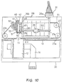
- Fig. 10 shows a view corresponding to that of Fig. 3 of a second embodiment of the present invention.
- the second embodiment of the invention differs from the first embodiment with respect to the location of the paper feed control member 40.
- the paper feed control member 40 is disposed on the side of the paper guide unit 26 opposite to the belt drive gear 91, i.e. on the left side in Fig. 10.
- the paper feed mechanism and the belt drive gear are arranged on opposite sides of the paper guide unit 26 and the platen 21 (the latter not being shown in Fig. 10).
- the belt 22 directly engages belt drive gear 91 as well as a gear 92 mounted on the printer base 30 next to the paper feed control member 40.
- Gear 92 comprises a spur gear portion meshing with belt 22 and a bevel gear portion meshing with the bevel gear 41 of the paper feed control member 40. Since the paper feed control member 40 and the other elements of the paper feed mechanism can be disposed separated from the belt drive gear 91, all of which require space, the surface area of the printer base 30 can be used more efficiently, thereby further facilitating to make the printer compact. Since the belt drive gear 91 and the paper feed control member 40 are separated in this embodiment, the paper feed control member 40 is driven by means of gear 92, which in turn is driven via the timing belt 22.
- the other component parts of the printer of the second embodiment are the same as those of the first embodiment, and the same reference numerals are used to designate same or identical parts in Figs. 3 and 10. Another explanation of those parts can thus be omitted here. Also, since the operation in the character mode, graphics mode and fast paper feed mode is the same as in the first embodiment, an explanation is omitted here.
- Fig. 11 is a view similar to Figs. 3 and 10 of a third embodiment of the present invention.
- the paper feed control member 40 and the elements controlled by it are disposed separate from the belt drive gear 25 driven by the motor (not shown). Therefore, like with the second embodiment, there is a more efficient use of the surface area of the printer base 30 allowing to make the printer even more compact.
- the third embodiment differs from the first embodiment in that in the latter case the bevel gear 41 forms an integral part of the paper feed control member 40 whereas in the former case the bevel gear 94 and the paper feed control member 40' are separated from each other and connected by means of a shaft 93 to transfer a rotation of bevel gear 94 to the paper feed control member 40'.
- the belt drive gear 25, the belt gear 24 and the bevel gear 94 are disposed on the printer base 30 on one side of the paper guide unit 26 (and thus the platen) whereas the paper feed control member 40' and the elements controlled by it are located on the opposite side of the paper guide unit 26 and connected to each other by means of shaft 93.
- the paper feed control member may be driven in a number of ways, i.e. directly by the belt drive gear which in turn is driven by the motor, via the timing belt or via the shaft 93.
- the embodiment of Fig. 11 could be further modified by having timing belt 22 directly meshing with gear 25 instead of gear 24 and by driving gear 25 through engagement with a pinion provided on the motor shaft.
- cam grooves i.e. groove-shaped cam profiles and cam follower pins tracing the cam grooves are employed to achieve and control paper feed.
- the invention is not limited to groove-shaped cam profiles but may employ other cam means, for instance protruding or ridge-shaped cam profiles, suitable to achieve the desired function.
- ratchet wheel 56 engages a corresponding groove of the portion 64 of paper feed lever 60 in order to rotate ratchet wheel 56 as paper feed lever 60 rotates.
- the paper feed lever 60 could have a sector gear portion meshing with a corresponding toothed portion on part of the circumference of ratchet wheel 56.
- the rotational axis of the ratchet wheel 56 would be the same as that of the paper feed shaft 90, but the rotational axis of the paper feed lever 60 would be parallel to but displaced with respect to the axis of the paper feed shaft.
- the spring 54 urging ratchet wheel 56 against ratchet wheel 58 would rest on some part of the frame or on a seat fixed to the respective end of the paper feed shaft.
- Such alternative construction may serve to facilitate assembling work.
- Fig. 12 shows a circuit block diagram of an electronic tabletop calculator equipped with a printer according to the present invention and a drive control device that controls the printer.
- a CPU 201 controls the entire calculator which includes a ROM 202, a RAM 203, a timer 204, a display device 205, a keyboard 206 and the printer unit 220.
- the CPU 201 is connected to the component parts of the printer 220 via an I/O port not shown.
- the print head 211 is connected to the CPU 201 via a head drive circuit 208, the motor 210 is connected via a motor drive circuit 207, and the home position sensor 212 corresponding to home position sensor 32 in Fig. 1 is connected via a detection circuit 209.
- a stepper motor may be used as the motor 210, and the arrangement is preferably such that there is a linear relationship between the angle of rotation of the motor shaft and the position of the print head. Then, by starting from the home position of the print head as detected by the home position sensor 212 as a reference position, the position of the print head can be easily controlled by the number of steps of the stepper motor. By counting the number of steps the CPU exactly knows the current position of the print head. That is, the position of the print head is processed by the CPU 201 which uses RAM 203 to count the number of steps of the stepper motor and compares the count with numbers of steps previously stored in ROM 202.
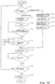
- step C0 After start of the control method it is judged in step C0 which printing mode has been selected. Since the character mode has been selected in this example, the control proceeds to step C1 and the motor is rotated in a forward direction so that the print head 11 is moved from its home position P1 toward its position P2. At this time, it has already been confirmed by means of the home position sensor 212 that the print head 11 actually is in its home position, and wile moving the print head, the CPU 201 counts the distance by which the print head is moved based on the number of steps of the stepper motor 210.
- step C3 it is judged whether or not all printing of the current line has been completed. If it has not been completed steps C2 and C3 are repeated until the printing for the current line has been completed.
- step C4 The printing operation is performed while the print head 11 moves from the printing start position P2 to the farthest position P4.
- judgement is performed in step C4 to determine whether or not the print head is at position P3 or has passed P3, thus to determine whether cam follower pin 51 has passed junction 76 between cam groove portions 73 and 74. If the print head 11 has not yet arrived at or passed position P3, a short motor feed in step C5 and judgement in step C4 are repeated until the print head has moved to P3.
- the print head must have reached position P3 before the motor is reversed to ensure that cam follower pin 51 has passed junction 76 to be able to trace cam groove portion 74 to enable paper feed wile the print head is being returned.
- step C6 the processing proceeds to step C6 where the motor is reversed to move print head 11 back to its home position P1.
- step C7 The return movement of the print head 11 is continued until it is judged in step C7 that the print head has arrived at its home position P1. Wile the print head moves from position P3 to position P1 the paper is fed by an amount corresponding to ⁇ 1 (Fig. 8a) as explained in detail before.
- step C8 judgement is performed in step C8 to determine whether or not a further line is to be printed. If printing is to be continued the processing returns to step C0 to be repeated. Otherwise the motor is stopped in step C9 and one operation cycle is terminated.
- step C0 If in step C0 it is decided that graphics mode has been selected, the processing proceeds to step G1 and the motor is rotated in a forward direction to move the print head to the position P2. Then, printing is started in step G2 and continued until the prescribed number of dots have been printed (step G3) after which the motor is rotated forward for a prescribed amount (step G4) until the print head passes position P4 and arrives at position P5, where the processing proceeds to step C6 to reverse the motor and return the print head. During the return movement of the print head the paper is fed by an amount corresponding to ⁇ 2 (Fig. 8a) as explained in detail before.
- the motor 210 is controlled to repeatedly move the print head from its home position P1 to the position P3 and from the position P3 back to the position P1. This cycle is repeated for a number of times corresponding to the desired amount of paper to be fed without any printing being performed.
- the print mode depends on the stroke of the reciprocating movement of the paper feed control member, this stroke being controlled by controlling the angle of rotation of the motor from its reference position up to the position where it is reversed.
- This stroke of the paper feed control member does not necessarily have to be in a linear relationship with the stroke of the carriage.
Landscapes
- Common Mechanisms (AREA)
- Character Spaces And Line Spaces In Printers (AREA)
Applications Claiming Priority (4)
| Application Number | Priority Date | Filing Date | Title |
|---|---|---|---|
| JP264308/91 | 1991-10-14 | ||
| JP26430891 | 1991-10-14 | ||
| JP79951/92 | 1992-04-01 | ||
| JP7995192 | 1992-04-01 |
Publications (3)
| Publication Number | Publication Date |
|---|---|
| EP0537679A2 true EP0537679A2 (de) | 1993-04-21 |
| EP0537679A3 EP0537679A3 (en) | 1993-12-22 |
| EP0537679B1 EP0537679B1 (de) | 1996-06-26 |
Family
ID=26420930
Family Applications (1)
| Application Number | Title | Priority Date | Filing Date |
|---|---|---|---|
| EP92117459A Expired - Lifetime EP0537679B1 (de) | 1991-10-14 | 1992-10-13 | Antriebsmechanismus für Drucker |
Country Status (4)
| Country | Link |
|---|---|
| US (1) | US5354136A (de) |
| EP (1) | EP0537679B1 (de) |
| JP (1) | JP3334185B2 (de) |
| DE (1) | DE69211804T2 (de) |
Cited By (4)
| Publication number | Priority date | Publication date | Assignee | Title |
|---|---|---|---|---|
| EP0659568A3 (de) * | 1993-12-27 | 1997-07-09 | Seiko Epson Corp | Tintenstrahldrucker. |
| EP1249352A1 (de) * | 2001-04-11 | 2002-10-16 | Agilent Technologies, Inc. (a Delaware corporation) | Tintenstrahldrucksystem unter Verwendung eines einzigen Motors für Aufzeichnungsträgertransport und Wagenbewegung |
| US7058834B2 (en) | 2001-04-26 | 2006-06-06 | Paul Richard Woods | Scan-based state save and restore method and system for inactive state power reduction |
| ITMO20130255A1 (it) * | 2013-09-18 | 2015-03-19 | Custom Engineering S P A | Meccanismo di stampa |
Families Citing this family (9)
| Publication number | Priority date | Publication date | Assignee | Title |
|---|---|---|---|---|
| JPH0766949A (ja) * | 1993-08-24 | 1995-03-10 | Canon Inc | ファクシミリ装置 |
| US6089773A (en) * | 1997-12-12 | 2000-07-18 | Lexmark International, Inc. | Print media feed system for an ink jet printer |
| ITTO20020304A1 (it) * | 2002-04-08 | 2003-10-08 | Olivetti Tecnost | Dispositivo di tracinamento carta per stampanti a punti,ad esempio stampanti fotografiche a getto d'inchiostro. |
| JP3809421B2 (ja) * | 2003-01-31 | 2006-08-16 | キヤノン株式会社 | 記録装置 |
| JP4613678B2 (ja) * | 2005-04-19 | 2011-01-19 | 船井電機株式会社 | 画像形成装置 |
| CN100526082C (zh) * | 2006-04-28 | 2009-08-12 | 光宝科技股份有限公司 | 用于驱动打印头维护装置的驱动模块 |
| WO2007149573A2 (en) * | 2006-06-22 | 2007-12-27 | Futurelogic, Inc. | Linear cam for positioning control in a printer |
| WO2007149572A2 (en) * | 2006-06-22 | 2007-12-27 | Futurelogic, Inc. | Rotary cam for positioning control in a printer |
| JP4877020B2 (ja) * | 2007-04-03 | 2012-02-15 | セイコーエプソン株式会社 | プリンタの送り駆動装置およびプリンタ |
Family Cites Families (19)
| Publication number | Priority date | Publication date | Assignee | Title |
|---|---|---|---|---|
| FR562222A (de) * | 1922-04-06 | 1923-11-07 | ||
| US4030588A (en) * | 1972-06-19 | 1977-06-21 | Canon Kabushiki Kaisha | Printer |
| US3986594A (en) * | 1974-11-27 | 1976-10-19 | Lrc, Inc. | Serial impact calculator printer |
| JPS54100808A (en) * | 1978-01-25 | 1979-08-08 | Suwa Seikosha Kk | Printer |
| FR2498524B1 (fr) * | 1981-01-27 | 1986-07-25 | Thomson Csf | Dispositif electromecanique d'impression pour imprimante du type serie-parallele et telecopieur comportant un tel dispositif |
| US4444521A (en) * | 1982-08-02 | 1984-04-24 | United Systems Corporation | Print medium advancing mechanism including print head retraction |
| JPS5952669A (ja) * | 1982-09-17 | 1984-03-27 | Seiko Epson Corp | サ−マルプリンタ |
| GB2126952B (en) * | 1982-09-17 | 1985-11-06 | Epson Corp | Serial printer |
| JPS63122572A (ja) * | 1986-11-13 | 1988-05-26 | Brother Ind Ltd | 印字装置 |
| EP0274266B1 (de) * | 1986-12-27 | 1993-07-28 | Canon Kabushiki Kaisha | Übertragungsvorrichtung für Motorantriebe für eine Aufzeichnungsvorrichtung |
| JPS63201750U (de) * | 1987-06-16 | 1988-12-26 | ||
| DE3729307C1 (de) * | 1987-09-02 | 1989-01-26 | Triumph Adler Ag | Schreib- oder aehnliche Maschine |
| JPS6487380A (en) * | 1987-09-30 | 1989-03-31 | Brother Ind Ltd | Thermal printer |
| JP2633883B2 (ja) * | 1988-01-30 | 1997-07-23 | キヤノン株式会社 | 記録装置 |
| US5136308A (en) * | 1988-08-18 | 1992-08-04 | Canon Kabushiki Kaisha | Recording apparatus |
| US5140344A (en) * | 1989-02-14 | 1992-08-18 | Canon Kabushiki Kaisha | Recording apparatus |
| JPH0350715A (ja) * | 1989-07-18 | 1991-03-05 | Nec Corp | パターン露光装置 |
| US5106216A (en) * | 1989-11-22 | 1992-04-21 | Samsung Electronics Co., Ltd. | Device for driving a platen and carriage of a printing machine |
| US5226743A (en) * | 1991-04-16 | 1993-07-13 | Hewlett-Packard Company | Method and apparatus for paper control in a printer |
-
1992
- 1992-10-12 JP JP27314492A patent/JP3334185B2/ja not_active Expired - Fee Related
- 1992-10-13 EP EP92117459A patent/EP0537679B1/de not_active Expired - Lifetime
- 1992-10-13 DE DE69211804T patent/DE69211804T2/de not_active Expired - Fee Related
- 1992-10-14 US US07/961,553 patent/US5354136A/en not_active Expired - Lifetime
Cited By (9)
| Publication number | Priority date | Publication date | Assignee | Title |
|---|---|---|---|---|
| EP0659568A3 (de) * | 1993-12-27 | 1997-07-09 | Seiko Epson Corp | Tintenstrahldrucker. |
| EP1249352A1 (de) * | 2001-04-11 | 2002-10-16 | Agilent Technologies, Inc. (a Delaware corporation) | Tintenstrahldrucksystem unter Verwendung eines einzigen Motors für Aufzeichnungsträgertransport und Wagenbewegung |
| US6533387B2 (en) | 2001-04-11 | 2003-03-18 | Agilent Technologies, Inc. | Inkjet printing system using single motor for print media advance and carriage motion |
| US7058834B2 (en) | 2001-04-26 | 2006-06-06 | Paul Richard Woods | Scan-based state save and restore method and system for inactive state power reduction |
| ITMO20130255A1 (it) * | 2013-09-18 | 2015-03-19 | Custom Engineering S P A | Meccanismo di stampa |
| WO2015040545A1 (en) * | 2013-09-18 | 2015-03-26 | Custom S.P.A. | Printing mechanism |
| CN105745082A (zh) * | 2013-09-18 | 2016-07-06 | 柯斯特姆股份公司 | 打印机构 |
| US9573394B2 (en) | 2013-09-18 | 2017-02-21 | Custom S.P.A. | Printing mechanism |
| RU2661809C2 (ru) * | 2013-09-18 | 2018-07-19 | Кастом С.П.А. | Печатающий механизм |
Also Published As
| Publication number | Publication date |
|---|---|
| JP3334185B2 (ja) | 2002-10-15 |
| US5354136A (en) | 1994-10-11 |
| DE69211804D1 (de) | 1996-08-01 |
| EP0537679A3 (en) | 1993-12-22 |
| HK1007991A1 (en) | 1999-04-30 |
| JPH05330182A (ja) | 1993-12-14 |
| DE69211804T2 (de) | 1996-11-28 |
| EP0537679B1 (de) | 1996-06-26 |
Similar Documents
| Publication | Publication Date | Title |
|---|---|---|
| EP0537679B1 (de) | Antriebsmechanismus für Drucker | |
| US5184902A (en) | Recording apparatus having a single drive source for conveying recording means and feeding recording medium | |
| US4920258A (en) | Recording apparatus with carriage-driving/sheet-feeding mechanism | |
| US4565461A (en) | Pitch-changeable, cam-actuated paper feed for serial printer | |
| US5276466A (en) | Recording apparatus | |
| GB2046177A (en) | Printer | |
| US5801744A (en) | Thermal printer | |
| US4707154A (en) | Printer | |
| HK1007991B (en) | Drive mechanism for a printer | |
| US4551033A (en) | Serial electric printer using single unidirectional motor | |
| US5788383A (en) | Recording apparatus having a single drive source for conveying recording means and feeding recording medium | |
| US5071266A (en) | Head engagement mechanism for thermal recording apparatus | |
| JPH0223356B2 (de) | ||
| US4591882A (en) | Printer electromagnetic clutch drive | |
| US4715737A (en) | Printer with paper feed roller disengagement mechanism | |
| US5926193A (en) | Printer having power transmission change-over mechanism for purging mechanism | |
| JPH06227082A (ja) | プリンタ | |
| JP4336948B2 (ja) | 液体噴射間隔切換装置、キャリッジ、液体噴射装置 | |
| JP5216311B2 (ja) | 2色印字転換機能を備えた印字装置 | |
| JP2001001594A (ja) | 送りねじ並びにシリアル型サーマルプリンタおよびその制御方法 | |
| US5482388A (en) | Detent mechanism and gear changeover apparatus in a recording apparatus | |
| US5263784A (en) | Sheet feeder for printer | |
| JPH0223357B2 (de) | ||
| JPH06344620A (ja) | 記録装置 | |
| JPH11286153A (ja) | タイミングベルト係合機構 |
Legal Events
| Date | Code | Title | Description |
|---|---|---|---|
| PUAI | Public reference made under article 153(3) epc to a published international application that has entered the european phase |
Free format text: ORIGINAL CODE: 0009012 |
|
| AK | Designated contracting states |
Kind code of ref document: A2 Designated state(s): DE FR GB IT |
|
| PUAL | Search report despatched |
Free format text: ORIGINAL CODE: 0009013 |
|
| AK | Designated contracting states |
Kind code of ref document: A3 Designated state(s): DE FR GB IT |
|
| 17P | Request for examination filed |
Effective date: 19940615 |
|
| 17Q | First examination report despatched |
Effective date: 19950719 |
|
| GRAH | Despatch of communication of intention to grant a patent |
Free format text: ORIGINAL CODE: EPIDOS IGRA |
|
| GRAA | (expected) grant |
Free format text: ORIGINAL CODE: 0009210 |
|
| AK | Designated contracting states |
Kind code of ref document: B1 Designated state(s): DE FR GB IT |
|
| ITF | It: translation for a ep patent filed | ||
| REF | Corresponds to: |
Ref document number: 69211804 Country of ref document: DE Date of ref document: 19960801 |
|
| ET | Fr: translation filed | ||
| PLBE | No opposition filed within time limit |
Free format text: ORIGINAL CODE: 0009261 |
|
| STAA | Information on the status of an ep patent application or granted ep patent |
Free format text: STATUS: NO OPPOSITION FILED WITHIN TIME LIMIT |
|
| 26N | No opposition filed | ||
| REG | Reference to a national code |
Ref country code: GB Ref legal event code: IF02 |
|
| PGFP | Annual fee paid to national office [announced via postgrant information from national office to epo] |
Ref country code: DE Payment date: 20071011 Year of fee payment: 16 |
|
| PGFP | Annual fee paid to national office [announced via postgrant information from national office to epo] |
Ref country code: IT Payment date: 20071026 Year of fee payment: 16 |
|
| PGFP | Annual fee paid to national office [announced via postgrant information from national office to epo] |
Ref country code: FR Payment date: 20071009 Year of fee payment: 16 Ref country code: GB Payment date: 20071010 Year of fee payment: 16 |
|
| GBPC | Gb: european patent ceased through non-payment of renewal fee |
Effective date: 20081013 |
|
| REG | Reference to a national code |
Ref country code: FR Ref legal event code: ST Effective date: 20090630 |
|
| PG25 | Lapsed in a contracting state [announced via postgrant information from national office to epo] |
Ref country code: DE Free format text: LAPSE BECAUSE OF NON-PAYMENT OF DUE FEES Effective date: 20090501 Ref country code: IT Free format text: LAPSE BECAUSE OF NON-PAYMENT OF DUE FEES Effective date: 20081013 |
|
| PG25 | Lapsed in a contracting state [announced via postgrant information from national office to epo] |
Ref country code: FR Free format text: LAPSE BECAUSE OF NON-PAYMENT OF DUE FEES Effective date: 20081031 |
|
| PG25 | Lapsed in a contracting state [announced via postgrant information from national office to epo] |
Ref country code: GB Free format text: LAPSE BECAUSE OF NON-PAYMENT OF DUE FEES Effective date: 20081013 |