EP0537793A2 - Appareil de transfert d'une image et de séparation d'une feuille - Google Patents
Appareil de transfert d'une image et de séparation d'une feuille Download PDFInfo
- Publication number
- EP0537793A2 EP0537793A2 EP92117845A EP92117845A EP0537793A2 EP 0537793 A2 EP0537793 A2 EP 0537793A2 EP 92117845 A EP92117845 A EP 92117845A EP 92117845 A EP92117845 A EP 92117845A EP 0537793 A2 EP0537793 A2 EP 0537793A2
- Authority
- EP
- European Patent Office
- Prior art keywords
- sheet
- transfer roller
- image
- voltage
- photoconductor drum
- Prior art date
- Legal status (The legal status is an assumption and is not a legal conclusion. Google has not performed a legal analysis and makes no representation as to the accuracy of the status listed.)
- Granted
Links
Images


Classifications
-
- G—PHYSICS
- G03—PHOTOGRAPHY; CINEMATOGRAPHY; ANALOGOUS TECHNIQUES USING WAVES OTHER THAN OPTICAL WAVES; ELECTROGRAPHY; HOLOGRAPHY
- G03G—ELECTROGRAPHY; ELECTROPHOTOGRAPHY; MAGNETOGRAPHY
- G03G15/00—Apparatus for electrographic processes using a charge pattern
- G03G15/65—Apparatus which relate to the handling of copy material
- G03G15/6532—Removing a copy sheet form a xerographic drum, band or plate
- G03G15/6535—Removing a copy sheet form a xerographic drum, band or plate using electrostatic means, e.g. a separating corona
-
- G—PHYSICS
- G03—PHOTOGRAPHY; CINEMATOGRAPHY; ANALOGOUS TECHNIQUES USING WAVES OTHER THAN OPTICAL WAVES; ELECTROGRAPHY; HOLOGRAPHY
- G03G—ELECTROGRAPHY; ELECTROPHOTOGRAPHY; MAGNETOGRAPHY
- G03G15/00—Apparatus for electrographic processes using a charge pattern
- G03G15/14—Apparatus for electrographic processes using a charge pattern for transferring a pattern to a second base
- G03G15/16—Apparatus for electrographic processes using a charge pattern for transferring a pattern to a second base of a toner pattern, e.g. a powder pattern, e.g. magnetic transfer
- G03G15/1665—Apparatus for electrographic processes using a charge pattern for transferring a pattern to a second base of a toner pattern, e.g. a powder pattern, e.g. magnetic transfer by introducing the second base in the nip formed by the recording member and at least one transfer member, e.g. in combination with bias or heat
- G03G15/167—Apparatus for electrographic processes using a charge pattern for transferring a pattern to a second base of a toner pattern, e.g. a powder pattern, e.g. magnetic transfer by introducing the second base in the nip formed by the recording member and at least one transfer member, e.g. in combination with bias or heat at least one of the recording member or the transfer member being rotatable during the transfer
- G03G15/1675—Apparatus for electrographic processes using a charge pattern for transferring a pattern to a second base of a toner pattern, e.g. a powder pattern, e.g. magnetic transfer by introducing the second base in the nip formed by the recording member and at least one transfer member, e.g. in combination with bias or heat at least one of the recording member or the transfer member being rotatable during the transfer with means for controlling the bias applied in the transfer nip
-
- G—PHYSICS
- G03—PHOTOGRAPHY; CINEMATOGRAPHY; ANALOGOUS TECHNIQUES USING WAVES OTHER THAN OPTICAL WAVES; ELECTROGRAPHY; HOLOGRAPHY
- G03G—ELECTROGRAPHY; ELECTROPHOTOGRAPHY; MAGNETOGRAPHY
- G03G15/00—Apparatus for electrographic processes using a charge pattern
- G03G15/65—Apparatus which relate to the handling of copy material
- G03G15/6532—Removing a copy sheet form a xerographic drum, band or plate
Definitions
- the present invention relates to an image-transfer and sheet-separating apparatus; more particularly to an apparatus for transferring onto a copy sheet an image, retained on an image receiver, toner-developed from a positive latent image, and for separating the sheet holding the transferred image from the image receiver.
- An image forming apparatus such as a copying machine will include an image-transfer and sheet-separating apparatus for transferring onto a copy sheet a toner image formed on a photoconductor drum serving as an image receiver.
- Conventional image-transfer and sheet-separating apparatus have an image-transfer charger for supplying a copy sheet with charge of reversed polarity to that carried by the toner, received from a corona charger, and a sheet-separating charger which functions by applying an alternating-current voltage to the copy sheet.
- One undesirable side effect in the conventional apparatus is, however, that environmentally undesirable ozone is generated by the corona charger.
- the apparatus therein adopts a negative development process, by which toner is adhered to discharged (i.e., image-negative) areas of a photoconductor drum through an electric field generated by development electrodes.
- a DC bias voltage of reversed polarity to that of the toner adhered to the photoconductor drum is applied to the transfer roller.
- a copy sheet is then transported between the photoconductor drum and the transfer roller, which presses the sheet against the drum, whereupon the toner-developed image on the photoconductor drum is transferred onto the sheet by agency of the DC bias voltage applied to the transfer roller.
- the sheet holding the transferred image is discharged by a charge-stripping needle provided adjacent the transfer roller.
- adhesion of toner to the photoconductor drum is of sufficiently reduced strength as to enable image transfer at low bias voltages. Additionally, adhesion of the sheet to the photoconductor drum is such that it detaches easily merely by being discharged with the charge-stripping needle.
- An image-transfer and sheet-separating apparatus transfers onto a copy sheet an image retained on an image receiver, toner-developed developed from a positive latent image, and subsequently separates the image-holding sheet from the image receiver.
- AC voltage superimposed on DC voltage is applied to a transfer roller which presses on the image receiver.
- a charge-stripping element which removes charge from the copy sheet, is disposed in a portion of the sheet-transport stream forward of a nipping position of the transfer roller and the image receiver.
- An image-transfer and sheet-separating apparatus transfers toner retained on the image receiver onto a copy sheet, and separates the sheet from the image receiver upon the transfer process.
- the apparatus includes a transfer roller which presses on the image receiver, and to which DC and AC voltages are applied.
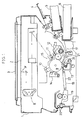
- an original retainer 2 on which an original is retained is disposed in an upper portion of a copying machine body 1, and a raisable original cover 3 is provided over the upper surface of the original retainer 2.
- a bypass tray 4 and detachable paper cassette cases 5 and 6 are attached.
- an optical exposure system 8 for obtaining image information from the original.
- the optical exposure system 8 consists of a light source, mirrors, a lens unit, etc.
- an image-forming section 15 comprising a photoconductor drum 9 on which an electrostatic latent image is formed and, surrounding the photoconductor drum 9, a main charger 10 for electrically charging the photoconductor drum 9 to a predetermined level; a blanking lamp 11 for discharging portions of latent image on the photoconductor drum 9 designated blank; a developing unit 12 for developing the electrostatic latent image on the photoconductor drum 9 with toner; an image-transfer and sheet-separating apparatus 13 for transferring the toner image from the photoconductor drum 9 onto a sheet, and for separating the sheet therefrom; and a cleaning unit 14 for removing excess toner from the photoconductor drum 9.
- paper supply paths 17 are provided between each of the bypass tray 4, the paper cassette case 5, and the paper cassette case 6, respectively, and the image forming section 15.
- a sheet-discharging path 18 is provided in a portion of the sheet transport stream forward of the image forming section 15.
- registration rollers 21 are provided, which regulate the start-timing for the transport of a copy sheet to between the photoconductor drum 9 and the image-transfer and sheet-separating apparatus 13.
- the sheet-discharging path 18 consists chiefly of a feed conveyer 22.
- a fixing unit 19 for fixing a transferred toner image onto a transported sheet, and rollers 20 for discharging the sheet from the fixing unit 19, are also provided in a portion of the sheet transport stream forward of the path 18.
- the image-transfer and sheet-separating apparatus 13 includes a case 30 pivotal along the direction indicated by arrow X about an axis O1.
- a transfer roller 31 is rotatably supported about an axis O2.
- the transfer roller 31 is formed from a pliable material, for example, polyurethane rubber, the resistivity of which is 107 ohm centimeters and the hardness of which is 17 Shore A.
- An upper portion of the transfer roller 31 presses on the lower surface of the photoconductor drum 9, and the transfer roller 31 is connected to a bias power supply unit 36.
- the bias power supply unit 36 has an AC power supply 37 and a DC power supply 38 for applying AC and DC voltages respectively, and AC voltage superimposed on DC voltage is thereby applied to the transfer roller 31.
- a fibrous-brush cleaning roller 32 is disposed under and pressed against the lower surface of the transfer roller 31.
- the brush roller 32 is rotated by a not-indicated driving mechanism, and cleans the surface of the transfer roller.
- the tip of a blade 33 fixed to an inner wall of the case 30 extends. The blade 33 scrapes toner from the brush roller 32.
- a eccentric wheel 34 rotatable about an axis O3 is disposed. Rotation of the eccentric wheel 34 about the axis O3 shifts the image-transfer and sheet-separating apparatus 13 along the direction X in Fig. 2.
- the turning angle of the eccentric wheel 34 is given to correspond to the thickness of a copy sheet.
- the axes O1, O2 and O3 lie in parallel.
- a charge-stripping brush 35 for removing charge from the reverse surface of the copy sheet is disposed.
- the charge-stripping brush 35 is of approximately the same length as the axial dimension of the transfer roller 31, and along the adjacent edge are conductive fibers of, for example, carbon. The tips of the charging-stripping brush 35 come into contact with the reverse surface of the copy sheet, and the opposite edge of the brush 35 is grounded. Accordingly, remnant charge on the sheet is removed.
- the copy machine includes a control unit 40 which is a microcomputer comprising a CPU, a ROM, a RAM etc., as shown Fig. 3.
- the control unit 40 is connected with an operation panel 41 disposed in the upper surface of the body 1.
- the operation panel 41 contains switches and an LED indicator.
- the control unit 40 is further connected with the bias power supply unit 36, a motor 39A for rotatively driving the transfer roller 31, a jam detector 42 composed of jam-detecting sensors provided in the supply paths 17 and the sheet-discharging path 18, and other input/output elements.
- step S1 When a copying operation is started by pressing a print key in the operation panel 41, at step S1, the first stage in a sheet-transporting process is performed. In this first stage, a copy sheet is transported from a selected of the paper cassettes to the registration rollers 21 via corresponding supply path 17. It then is determined at step S2 whether a jam has occurred during the first stage of the sheet-transporting process. This determination is made according to the status of the sensors in the jam detector 42. If no jam has occurred, the program runs to step S3.
- an image forming process is performed by the image forming section 15.
- the optical exposure system 8 obtains image information from the original on the original retainer 2.
- An electrostatic latent image is formed on the photoconductor drum 9 corresponding to the image information. Regions of the electrostatic latent image to be blanked are discharged by the blanking lamp 11, after which the latent image is developed with toner by the developing unit 12.
- the registration rollers 21 start to rotate at that timing wherein the forward end of the toner image on the drum 9 will be coincident with the forward end of the sheet, whereupon the second stage of the sheet-transport process, which includes image transfer and sheet discharge, is performed.
- a bias voltage consisting of an AC voltage superimposed on a DC voltage is applied to the transfer roller 31, and the transfer process is started.
- the sheet is charged by the DC voltage component with a charge of polarity reversed to that of the toner, and accordingly the toner image is transferred from the photoconductor drum 9 onto the sheet.
- the sheet is electrically discharged by the AC voltage; accordingly the possibility of separating failure is decreased.
- step S6 the program awaits the elapse of a timing corresponding to the circumferential length of the toner image on the photoconductor drum 9.
- step S7 application of the bias voltage is ceased, and the transfer process ends. It is determined at step S8 whether a jam has occurred in the second sheet-supplying process. If no jam has occurred, step S9 is executed.
- step S9 the sheet-discharging path 18, the fixing unit 19 and the discharging rollers 20 are driven, and accordingly the sheet is discharged from the machine body 1.
- step S10 is executed in order to halt the running of all components.
- step S11 the jam LED indicator in the operation panel 41 is illuminated, and an operator is thus notified that a jam has occurred.
- bias voltages employed in the sheet-separating function will be given in the following.
- Table 1 shows comparative examples using a DC bias voltage together with a charge-stripping element
- Table 2 shows embodiment examples using AC voltage superimposed on DC voltage in conjunction with the charge-stripping element.
- the first stage in the sheet-transporting process which supplies a sheet from a selected of the paper cassettes to the registration rollers 21 via the corresponding supply path 17, is carried out at step S21.
- step S22 it is determined whether sheet jamming has occurred in the first stage sheet-transporting process. This determination is made according to the status of the sensors comprising the jam detector 42. If no jam has occurred, the program proceeds to step S23.
- an image forming process is carried out by the image forming section 15.
- the optical exposure system 8 obtains image information from the original on the original retainer 2, and an electrostatic latent image is formed on the photoconductor drum 9 corresponding to the image information. Regions of the electrostatic latent image on the photoconductor drum 9 to be blanked are discharged by the blanking lamp 11, after which the latent image is developed with toner by the developing unit 12.
- the registration rollers 21 start to rotate at that timing wherein the forward end of the toner image on the drum 9 will be coincident with the forward end of the sheet, and thereupon the second stage of the sheet-transport process, for image transfer and sheet discharge, is carried out.
- the switch 39 of the bias power supply unit 36 is changed over to the AC power supply 38, switching it on, whereby AC bias voltage is applied to the transfer roller 31. Accordingly, the sheet is discharged and its forward end is separated from the photoconductor drum 9.
- the program awaits elapse of the predetermined timing at step S26.
- the predetermined timing is equivalent to that interval till the non-image area of the forward end of a sheet (about 5mm in length from the sheet's tip) passes the nipping position.
- step S27 the program runs to step S27. There, the switch 39 is changed over to the DC power supply 38, switching it on, shifting the voltage from AC to DC bias voltage. Thus the image transfer process is started, and accordingly the toner image on the photoconductor drum 9 is transferred to the sheet.
- step S28 the program awaits a timing corresponding to the circumferential length of the toner image on the photoconductor drum 9.
- step S29 the DC power supply 38 is switched off, accordingly the application of bias voltage is stopped and the image transfer process ends.
- step S30 it is determined whether jamming has occurred in the second sheet-supplying process. If not, the program proceeds to step S31.
- step S31 the sheet-discharging path 18, the fixing unit 19 and discharging rollers 20 are driven respectively; and accordingly the sheet is discharged from the body 1.
- step S32 all running components are halted.
- step S33 the jam LED indicator in the operation panel 41 is illuminated, notifying an operator that a jam has occurred.
- AC voltage is applied to the transfer roller while the non-image area in the forward end of the sheet is in the nipping position, thereby the non-image area on the sheet is discharged, accordingly separating the forward end of the sheet from the photoconductor drum 9 such that it cannot be re-attracted by the photoconductor drum.
Landscapes
- Physics & Mathematics (AREA)
- General Physics & Mathematics (AREA)
- Electrostatic Charge, Transfer And Separation In Electrography (AREA)
Applications Claiming Priority (2)
| Application Number | Priority Date | Filing Date | Title |
|---|---|---|---|
| JP3271064A JPH05107935A (ja) | 1991-10-18 | 1991-10-18 | 転写分離装置 |
| JP271064/91 | 1991-10-18 |
Publications (3)
| Publication Number | Publication Date |
|---|---|
| EP0537793A2 true EP0537793A2 (fr) | 1993-04-21 |
| EP0537793A3 EP0537793A3 (en) | 1993-09-08 |
| EP0537793B1 EP0537793B1 (fr) | 1996-07-17 |
Family
ID=17494894
Family Applications (1)
| Application Number | Title | Priority Date | Filing Date |
|---|---|---|---|
| EP92117845A Expired - Lifetime EP0537793B1 (fr) | 1991-10-18 | 1992-10-19 | Appareil de transfert d'une image et de séparation d'une feuille |
Country Status (4)
| Country | Link |
|---|---|
| US (2) | US5408300A (fr) |
| EP (1) | EP0537793B1 (fr) |
| JP (1) | JPH05107935A (fr) |
| DE (1) | DE69212264T2 (fr) |
Cited By (6)
| Publication number | Priority date | Publication date | Assignee | Title |
|---|---|---|---|---|
| EP0652492A1 (fr) * | 1993-11-09 | 1995-05-10 | Ricoh Company, Ltd | Appareil de formation d'images avec un membre de contact en contact avec un support d'image |
| EP0652494A3 (fr) * | 1993-11-10 | 1996-02-07 | Mita Industrial Co Ltd | Appareil de formation d'images avec un procédé de transfert par rouleau. |
| GB2296471A (en) * | 1994-12-23 | 1996-07-03 | Xerox Corp | Electrically biassed sheet stripping claw |
| DE10131652A1 (de) * | 2001-06-29 | 2003-01-16 | Nexpress Solutions Llc | Verfahren und Einrichtung zum Übertragen von Toner |
| US7681298B2 (en) | 2004-06-23 | 2010-03-23 | Profil Verbindungstechnik Gmbh & Co. Kg | Method for the manufacture of a component assembly comprising a sheet metal part and a functional element attached to it, a sheet metal part and also functional element |
| EP2570859A3 (fr) * | 2011-09-13 | 2017-10-04 | Ricoh Company, Ltd. | Appareil de formation d'images |
Families Citing this family (20)
| Publication number | Priority date | Publication date | Assignee | Title |
|---|---|---|---|---|
| JPH05107935A (ja) * | 1991-10-18 | 1993-04-30 | Mita Ind Co Ltd | 転写分離装置 |
| JPH09319234A (ja) * | 1996-05-29 | 1997-12-12 | Sharp Corp | 画像形成装置 |
| US5966559A (en) * | 1997-09-23 | 1999-10-12 | Eastman Kodak Company | Method and apparatus for sensing and accomodating different thickness paper stocks in an electrostatographic machine |
| JP2000181156A (ja) * | 1998-12-18 | 2000-06-30 | Canon Inc | 画像形成装置 |
| JP3075716B1 (ja) * | 1999-02-26 | 2000-08-14 | 京セラミタ株式会社 | 電子写真における転写装置 |
| JP4375133B2 (ja) | 2004-06-11 | 2009-12-02 | 船井電機株式会社 | レーザプリンタ |
| WO2008069224A1 (fr) * | 2006-12-06 | 2008-06-12 | Nec Corporation | Dispositif, procédé et programme de masquage d'informations |
| US20100033557A1 (en) * | 2008-07-28 | 2010-02-11 | Sony Corporation | Stereoscopic image display and method for producing the same |
| JP2010032675A (ja) * | 2008-07-28 | 2010-02-12 | Sony Corp | 立体画像表示装置の製造方法および立体画像表示装置 |
| JP4582219B2 (ja) * | 2008-07-28 | 2010-11-17 | ソニー株式会社 | 立体画像表示装置およびその製造方法 |
| JP4525808B2 (ja) * | 2008-07-28 | 2010-08-18 | ソニー株式会社 | 立体画像表示装置およびその製造方法 |
| JP4582218B2 (ja) * | 2008-07-28 | 2010-11-17 | ソニー株式会社 | 立体画像表示装置およびその製造方法 |
| KR20110106160A (ko) * | 2010-03-22 | 2011-09-28 | (주)인터큐비트 | 다중 디스플레이를 이용한 초고해상도 영상 재생 시스템 |
| US8320817B2 (en) * | 2010-08-18 | 2012-11-27 | Eastman Kodak Company | Charge removal from a sheet |
| JP5810684B2 (ja) * | 2010-11-04 | 2015-11-11 | 株式会社リコー | 画像形成装置 |
| JP5888588B2 (ja) * | 2010-11-19 | 2016-03-22 | 株式会社リコー | 転写装置及び画像形成装置 |
| JP5678841B2 (ja) * | 2011-06-02 | 2015-03-04 | 株式会社リコー | 画像形成装置 |
| JP5891628B2 (ja) * | 2011-07-15 | 2016-03-23 | 株式会社リコー | 画像形成装置 |
| JP6492956B2 (ja) * | 2015-05-15 | 2019-04-03 | 株式会社リコー | 画像形成装置 |
| JP6628130B2 (ja) * | 2015-10-14 | 2020-01-08 | 株式会社リコー | 画像形成装置 |
Family Cites Families (28)
| Publication number | Priority date | Publication date | Assignee | Title |
|---|---|---|---|---|
| JPS5441904B2 (fr) * | 1971-09-20 | 1979-12-11 | ||
| NL179517C (nl) * | 1974-11-18 | 1986-09-16 | Oce Van Der Grinten N V P A Oc | Inrichting voor het elektrostatisch overdragen van een poederbeeld vanaf een drager naar een ontvangstmateriaal. |
| JPS54137347A (en) * | 1978-04-18 | 1979-10-25 | Olympus Optical Co Ltd | Zerographic apparatus |
| US4190348A (en) * | 1978-10-02 | 1980-02-26 | Xerox Corporation | Lead edge transfer switching |
| JPS5660470A (en) * | 1979-10-23 | 1981-05-25 | Minolta Camera Co Ltd | Transfer paper separation method in electronic copying machine |
| JPS5680075A (en) * | 1979-12-06 | 1981-07-01 | Toshiba Corp | Exfoliating device of recording paper |
| US4431301A (en) * | 1980-03-12 | 1984-02-14 | Tokyo Shibaura Denki Kabushiki Kaisha | Electrostatic copying apparatus with means for preventing contamination of reverse side of copying medium |
| JPS56147152A (en) * | 1980-04-17 | 1981-11-14 | Copyer Co Ltd | Image transfer method of electrophotographic copying machine |
| JPS5844472A (ja) * | 1981-09-11 | 1983-03-15 | Ricoh Co Ltd | 記録方式におけるトナ−転写方法 |
| US4449808A (en) * | 1982-06-07 | 1984-05-22 | Xerox Corporation | Electrostatic detack apparatus and method |
| JPS59181364A (ja) * | 1983-03-31 | 1984-10-15 | Toshiba Corp | 画像形成装置 |
| JPS6118972A (ja) * | 1984-07-05 | 1986-01-27 | Konishiroku Photo Ind Co Ltd | 光導電性トナ−を用いる記録方法 |
| JPH0677170B2 (ja) * | 1984-12-10 | 1994-09-28 | 富士ゼロックス株式会社 | 電子複写機の転写補助装置 |
| JPS6290675A (ja) * | 1985-10-17 | 1987-04-25 | Fuji Xerox Co Ltd | カラ−複写機の転写装置 |
| JPS6296983A (ja) * | 1985-10-24 | 1987-05-06 | Canon Inc | 画像形成装置 |
| GB2204508B (en) * | 1987-03-31 | 1991-03-13 | Brother Ind Ltd | Image recording system capable of using both negative and positive originals for reproducing a print |
| JPH07113802B2 (ja) * | 1987-06-30 | 1995-12-06 | キヤノン株式会社 | 画像形成装置 |
| JPH01149079A (ja) * | 1987-12-07 | 1989-06-12 | Ricoh Co Ltd | 転写装置 |
| US5168313A (en) * | 1988-04-28 | 1992-12-01 | Kabushiki Kaisha Toshiba | Toner image transfer method and device for electrophotographic printing apparatus |
| US5253022A (en) * | 1989-05-18 | 1993-10-12 | Canon Kabushiki Kaisha | Image forming apparatus |
| US5130752A (en) * | 1989-05-24 | 1992-07-14 | Mita Industrial Co., Ltd. | Transfer device with a ribbed guiding member |
| US5276489A (en) * | 1989-09-16 | 1994-01-04 | Canon Kabushiki Kaisha | Image forming apparatus with transfer roller with guide means which adjusts to movements of the roller |
| JPH07117793B2 (ja) * | 1989-11-10 | 1995-12-18 | 旭光学工業株式会社 | 電子写真装置の転写装置 |
| JPH03294884A (ja) * | 1990-04-13 | 1991-12-26 | Asahi Optical Co Ltd | 電子写真プリンタのスキュー防止構造 |
| US5132654A (en) * | 1990-06-01 | 1992-07-21 | Eastman Kodak Company | Device for facilitating receiver member separation |
| JPH0486878A (ja) * | 1990-07-31 | 1992-03-19 | Toshiba Corp | 記録装置 |
| US5101238A (en) * | 1991-01-18 | 1992-03-31 | Eastman Kodak Company | Roller transfer assembly |
| JPH05107935A (ja) * | 1991-10-18 | 1993-04-30 | Mita Ind Co Ltd | 転写分離装置 |
-
1991
- 1991-10-18 JP JP3271064A patent/JPH05107935A/ja active Pending
-
1992
- 1992-10-09 US US07/958,733 patent/US5408300A/en not_active Expired - Fee Related
- 1992-10-19 EP EP92117845A patent/EP0537793B1/fr not_active Expired - Lifetime
- 1992-10-19 DE DE69212264T patent/DE69212264T2/de not_active Expired - Fee Related
-
1995
- 1995-11-17 US US08/560,508 patent/US5689758A/en not_active Expired - Fee Related
Cited By (10)
| Publication number | Priority date | Publication date | Assignee | Title |
|---|---|---|---|---|
| EP0652492A1 (fr) * | 1993-11-09 | 1995-05-10 | Ricoh Company, Ltd | Appareil de formation d'images avec un membre de contact en contact avec un support d'image |
| US5585896A (en) * | 1993-11-09 | 1996-12-17 | Ricoh Company, Ltd. | Image forming apparatus with a contact member contacting an image carrier |
| EP0652494A3 (fr) * | 1993-11-10 | 1996-02-07 | Mita Industrial Co Ltd | Appareil de formation d'images avec un procédé de transfert par rouleau. |
| US5572305A (en) * | 1993-11-10 | 1996-11-05 | Mita Industrial Co., Ltd. | Image forming apparatus employing movable support for transfer roller |
| GB2296471A (en) * | 1994-12-23 | 1996-07-03 | Xerox Corp | Electrically biassed sheet stripping claw |
| GB2296471B (en) * | 1994-12-23 | 1997-11-19 | Xerox Corp | Electrically biassed sheet stripping apparatus |
| DE10131652A1 (de) * | 2001-06-29 | 2003-01-16 | Nexpress Solutions Llc | Verfahren und Einrichtung zum Übertragen von Toner |
| US6618571B2 (en) | 2001-06-29 | 2003-09-09 | Nexpress Solutions Llc | Process and device for transferring toner |
| US7681298B2 (en) | 2004-06-23 | 2010-03-23 | Profil Verbindungstechnik Gmbh & Co. Kg | Method for the manufacture of a component assembly comprising a sheet metal part and a functional element attached to it, a sheet metal part and also functional element |
| EP2570859A3 (fr) * | 2011-09-13 | 2017-10-04 | Ricoh Company, Ltd. | Appareil de formation d'images |
Also Published As
| Publication number | Publication date |
|---|---|
| EP0537793A3 (en) | 1993-09-08 |
| EP0537793B1 (fr) | 1996-07-17 |
| US5408300A (en) | 1995-04-18 |
| DE69212264T2 (de) | 1997-03-06 |
| DE69212264D1 (de) | 1996-08-22 |
| JPH05107935A (ja) | 1993-04-30 |
| US5689758A (en) | 1997-11-18 |
Similar Documents
| Publication | Publication Date | Title |
|---|---|---|
| EP0537793B1 (fr) | Appareil de transfert d'une image et de séparation d'une feuille | |
| EP0666518B1 (fr) | Appareil de formation d'images | |
| US5621509A (en) | Apparatus and method for cleaning a transfer device of an image forming apparatus | |
| US5857132A (en) | Apparatus and method for cleaning a transfer device of an image forming apparatus | |
| JPH07248693A (ja) | 画像形成装置 | |
| US5822649A (en) | Apparatus for cleaning a transfer device of an image forming apparatus | |
| JPH0635279A (ja) | 画像形成装置 | |
| JPH0962123A (ja) | 画像形成装置および接触式転写手段の清掃方法 | |
| JPH11119559A (ja) | 画像形成装置 | |
| JP3063155B2 (ja) | 画像形成装置の制御方法 | |
| JPH07302008A (ja) | 画像形成装置 | |
| JPH09190089A (ja) | 画像形成装置 | |
| JP2759487B2 (ja) | 画像形成装置 | |
| JPH11258965A (ja) | 画像形成装置 | |
| US5970296A (en) | Image forming apparatus | |
| JP3222359B2 (ja) | 画像形成装置 | |
| JP2890054B2 (ja) | 画像形成装置 | |
| JP2687582B2 (ja) | 画像形成装置 | |
| JPH11258919A (ja) | 画像形成装置 | |
| JPH0954503A (ja) | 画像形成装置 | |
| JP3310069B2 (ja) | 画像形成装置 | |
| JPH10186889A (ja) | 画像形成装置 | |
| JPH1138778A (ja) | 画像形成装置 | |
| JPH0234883A (ja) | 静電記録装置 | |
| JPH05107938A (ja) | 転写分離装置 |
Legal Events
| Date | Code | Title | Description |
|---|---|---|---|
| PUAI | Public reference made under article 153(3) epc to a published international application that has entered the european phase |
Free format text: ORIGINAL CODE: 0009012 |
|
| AK | Designated contracting states |
Kind code of ref document: A2 Designated state(s): DE FR GB IT |
|
| PUAL | Search report despatched |
Free format text: ORIGINAL CODE: 0009013 |
|
| AK | Designated contracting states |
Kind code of ref document: A3 Designated state(s): DE FR GB IT |
|
| 17P | Request for examination filed |
Effective date: 19931014 |
|
| 17Q | First examination report despatched |
Effective date: 19950109 |
|
| GRAH | Despatch of communication of intention to grant a patent |
Free format text: ORIGINAL CODE: EPIDOS IGRA |
|
| GRAH | Despatch of communication of intention to grant a patent |
Free format text: ORIGINAL CODE: EPIDOS IGRA |
|
| GRAA | (expected) grant |
Free format text: ORIGINAL CODE: 0009210 |
|
| AK | Designated contracting states |
Kind code of ref document: B1 Designated state(s): DE FR GB IT |
|
| ET | Fr: translation filed | ||
| REF | Corresponds to: |
Ref document number: 69212264 Country of ref document: DE Date of ref document: 19960822 |
|
| ITF | It: translation for a ep patent filed | ||
| PLBE | No opposition filed within time limit |
Free format text: ORIGINAL CODE: 0009261 |
|
| STAA | Information on the status of an ep patent application or granted ep patent |
Free format text: STATUS: NO OPPOSITION FILED WITHIN TIME LIMIT |
|
| 26N | No opposition filed | ||
| PGFP | Annual fee paid to national office [announced via postgrant information from national office to epo] |
Ref country code: FR Payment date: 19971009 Year of fee payment: 6 |
|
| PGFP | Annual fee paid to national office [announced via postgrant information from national office to epo] |
Ref country code: GB Payment date: 19971010 Year of fee payment: 6 |
|
| PGFP | Annual fee paid to national office [announced via postgrant information from national office to epo] |
Ref country code: DE Payment date: 19971024 Year of fee payment: 6 |
|
| PG25 | Lapsed in a contracting state [announced via postgrant information from national office to epo] |
Ref country code: GB Free format text: LAPSE BECAUSE OF NON-PAYMENT OF DUE FEES Effective date: 19981019 |
|
| GBPC | Gb: european patent ceased through non-payment of renewal fee |
Effective date: 19981019 |
|
| PG25 | Lapsed in a contracting state [announced via postgrant information from national office to epo] |
Ref country code: FR Free format text: LAPSE BECAUSE OF NON-PAYMENT OF DUE FEES Effective date: 19990630 |
|
| REG | Reference to a national code |
Ref country code: FR Ref legal event code: ST |
|
| PG25 | Lapsed in a contracting state [announced via postgrant information from national office to epo] |
Ref country code: DE Free format text: LAPSE BECAUSE OF NON-PAYMENT OF DUE FEES Effective date: 19990803 |
|
| PG25 | Lapsed in a contracting state [announced via postgrant information from national office to epo] |
Ref country code: IT Free format text: LAPSE BECAUSE OF NON-PAYMENT OF DUE FEES;WARNING: LAPSES OF ITALIAN PATENTS WITH EFFECTIVE DATE BEFORE 2007 MAY HAVE OCCURRED AT ANY TIME BEFORE 2007. THE CORRECT EFFECTIVE DATE MAY BE DIFFERENT FROM THE ONE RECORDED. Effective date: 20051019 |