EP0538044A2 - Appareil de marquage par laser avec une qualité d'impression améliorée - Google Patents
Appareil de marquage par laser avec une qualité d'impression améliorée Download PDFInfo
- Publication number
- EP0538044A2 EP0538044A2 EP92309431A EP92309431A EP0538044A2 EP 0538044 A2 EP0538044 A2 EP 0538044A2 EP 92309431 A EP92309431 A EP 92309431A EP 92309431 A EP92309431 A EP 92309431A EP 0538044 A2 EP0538044 A2 EP 0538044A2
- Authority
- EP
- European Patent Office
- Prior art keywords
- spots
- column
- mirror
- exit lens
- beams
- Prior art date
- Legal status (The legal status is an assumption and is not a legal conclusion. Google has not performed a legal analysis and makes no representation as to the accuracy of the status listed.)
- Granted
Links
Images



Classifications
-
- B—PERFORMING OPERATIONS; TRANSPORTING
- B23—MACHINE TOOLS; METAL-WORKING NOT OTHERWISE PROVIDED FOR
- B23K—SOLDERING OR UNSOLDERING; WELDING; CLADDING OR PLATING BY SOLDERING OR WELDING; CUTTING BY APPLYING HEAT LOCALLY, e.g. FLAME CUTTING; WORKING BY LASER BEAM
- B23K26/00—Working by laser beam, e.g. welding, cutting or boring
- B23K26/02—Positioning or observing the workpiece, e.g. with respect to the point of impact; Aligning, aiming or focusing the laser beam
- B23K26/06—Shaping the laser beam, e.g. by masks or multi-focusing
- B23K26/0604—Shaping the laser beam, e.g. by masks or multi-focusing by a combination of beams
- B23K26/0608—Shaping the laser beam, e.g. by masks or multi-focusing by a combination of beams in the same heat affected zone [HAZ]
-
- B—PERFORMING OPERATIONS; TRANSPORTING
- B23—MACHINE TOOLS; METAL-WORKING NOT OTHERWISE PROVIDED FOR
- B23K—SOLDERING OR UNSOLDERING; WELDING; CLADDING OR PLATING BY SOLDERING OR WELDING; CUTTING BY APPLYING HEAT LOCALLY, e.g. FLAME CUTTING; WORKING BY LASER BEAM
- B23K26/00—Working by laser beam, e.g. welding, cutting or boring
- B23K26/02—Positioning or observing the workpiece, e.g. with respect to the point of impact; Aligning, aiming or focusing the laser beam
- B23K26/06—Shaping the laser beam, e.g. by masks or multi-focusing
-
- B—PERFORMING OPERATIONS; TRANSPORTING
- B23—MACHINE TOOLS; METAL-WORKING NOT OTHERWISE PROVIDED FOR
- B23K—SOLDERING OR UNSOLDERING; WELDING; CLADDING OR PLATING BY SOLDERING OR WELDING; CUTTING BY APPLYING HEAT LOCALLY, e.g. FLAME CUTTING; WORKING BY LASER BEAM
- B23K26/00—Working by laser beam, e.g. welding, cutting or boring
- B23K26/02—Positioning or observing the workpiece, e.g. with respect to the point of impact; Aligning, aiming or focusing the laser beam
- B23K26/06—Shaping the laser beam, e.g. by masks or multi-focusing
- B23K26/064—Shaping the laser beam, e.g. by masks or multi-focusing by means of optical elements, e.g. lenses, mirrors or prisms
- B23K26/0643—Shaping the laser beam, e.g. by masks or multi-focusing by means of optical elements, e.g. lenses, mirrors or prisms comprising mirrors
-
- B—PERFORMING OPERATIONS; TRANSPORTING
- B23—MACHINE TOOLS; METAL-WORKING NOT OTHERWISE PROVIDED FOR
- B23K—SOLDERING OR UNSOLDERING; WELDING; CLADDING OR PLATING BY SOLDERING OR WELDING; CUTTING BY APPLYING HEAT LOCALLY, e.g. FLAME CUTTING; WORKING BY LASER BEAM
- B23K26/00—Working by laser beam, e.g. welding, cutting or boring
- B23K26/02—Positioning or observing the workpiece, e.g. with respect to the point of impact; Aligning, aiming or focusing the laser beam
- B23K26/06—Shaping the laser beam, e.g. by masks or multi-focusing
- B23K26/0665—Shaping the laser beam, e.g. by masks or multi-focusing by beam condensation on the workpiece, e.g. for focusing
-
- G—PHYSICS
- G06—COMPUTING OR CALCULATING; COUNTING
- G06K—GRAPHICAL DATA READING; PRESENTATION OF DATA; RECORD CARRIERS; HANDLING RECORD CARRIERS
- G06K1/00—Methods or arrangements for marking the record carrier in digital fashion
- G06K1/12—Methods or arrangements for marking the record carrier in digital fashion otherwise than by punching
- G06K1/121—Methods or arrangements for marking the record carrier in digital fashion otherwise than by punching by printing code marks
-
- G—PHYSICS
- G06—COMPUTING OR CALCULATING; COUNTING
- G06K—GRAPHICAL DATA READING; PRESENTATION OF DATA; RECORD CARRIERS; HANDLING RECORD CARRIERS
- G06K1/00—Methods or arrangements for marking the record carrier in digital fashion
- G06K1/12—Methods or arrangements for marking the record carrier in digital fashion otherwise than by punching
- G06K1/126—Methods or arrangements for marking the record carrier in digital fashion otherwise than by punching by photographic or thermographic registration
Definitions
- This invention relates generally to apparatus for marking moving objects or substrates and more particularly, it relates to an improved laser marker apparatus for suitably coding paper labels, other substrates, printed material, plastic, painted surfaces and the like.
- Each laser defines an essentially collimated energy source which is focused, by the exit lens, into a dot of a predetermined small size for precision marking of article surfaces as they pass the output head substantially in the focal plane of the exit lens.
- the incident angle of each of the seven laser sources onto the exit lens is initially adjusted to provide a plurality of closely spaced and focused dots which define a vertical column of seven light dots from which the character matrix can be obtained by modulation of the dots as the article or substrate is moved past the exit lens.
- This invention provides a laser marker apparatus for marking indicia onto a substrate, comprising: a plurality of lasers arranged to emit output beams, an exit lens having a focal plane, and reflecting means arranged to direct the beams into the exit lens at predetermined angles between the beams to form the beams into a first column of first spots having predetermined separations in the focal plane of the exit lens, Characterised by the reflecting means being movable to at least one additional position, each additional position forming an additional column of spots in the focal plane of the exit lens, the spots formed by all of said columns being interleaved to create a composite column of spots with smaller separations.
- each of the first spots is determined by the angular difference between the output beams.
- the directing mirror is movable in a first direction so as to form a second column of second spots on the substrate each of the second spots is disposed above a corresponding one of the first spots.
- the reflecting means can be further movable in a second direction so as to form a third column of third spots on the substrate. Each of the third spots is disposed below a corresponding one of the first spots.
- FIG. 1 and 2 show a diagrammatical representation of a laser marker apparatus 10 constructed in accordance with the principles of the present invention.
- the laser marker apparatus of the present invention is adapted to mark or inscribe alphanumeric characters or other symbols definable within a matrix of predetermined number of dot rows onto the surface of movable articles, such as product packaging, beverage containers, bottle closures, labels, substrates and the like.
- the laser apparatus 10 includes a housing or cabinet 12 mounted on a support stand structure 14 and being adapted to receive a source of power via an A.C. wall-plug 16 and a power conditioning unit 18.
- the cabinet 12 houses seven lasers 20a-20g, seven RF laser excitation sources 22 over the respective lasers, seven turning mirrors 24a-24g, an interior directing mirror 26, and a microprocessor controller 28.
- a laser head unit 30 is mounted on the exterior of the upper end portion of the cabinet 12 via mounting flange 32.
- the laser head unit 30 comprises a horizontal beam delivery tube 34, an exterior directing mirror 36, a vertical beam delivery tube 38, and an exit lens 40.
- the directing mirror 36 is located at the intersection of the horizontal and vertical delivery tubes 34 and 38.
- the exit lens 40 is preferably arranged at the lower end of the vertical tube 38 so as to permit focusing.
- the seven lasers 20a-20g are CO2 gas lasers arranged vertically in the Y-direction within the cabinet 12, as illustrated in Figures 1 and 2.
- the light output beams from the lasers are passed through their respective output ends 44 in the X-direction and then impinge upon corresponding seven turning mirrors 24a-24g.
- the seven lasers 20a-20g direct substantially collimated light beams, which have a divergence of approximately 4 milliradians, into the corresponding seven turning mirrors 24a-24g.
- the turning mirrors reflect the beams off the directing mirror 26, through the delivery tube 34, and into the directing mirror 36. Thereafter, the beams are passed through the delivery tube 38 and into optical contact with the exit lens 40.
- the path of the light output beam from one of the lasers (i.e., laser 20a) to a marking article 46 when the directing mirror 26 is in the initial or reference position is illustrated by solid line 48 in Figure 2.
- the laser output beams from the lasers 20a-20g are focused as seven discrete spots or dots 50 onto the surface of the article 46 (one of which is shown in Figure 2).
- the seven discrete dots extend preferably along a line in the X-direction which is transverse to the direction of the article movement (which is in the Z-direction, that is perpendicular to the plane of the drawing).
- the seven discrete dots 50 define reference marking spots when the directing mirror 26 is positioned in the reference position shown in solid line in Figure 2.
- This line in the X-direction defines a single column of the characters or symbols to be marked.
- each laser describes a track or line on the article surface which defines a corresponding row of the character matrix to be marked.
- the seven discrete dots 50 are uniformly spaced thereby forming evenly spaced parallel character rows.
- the turning mirrors 24a-24g are rigidly mounted and do not move during normal marking operations. However, the turning mirrors are adjustable for initial system alignment to provide the necessary angular separation between adjacent beams but do not generally require further movement thereafter. This is achieved by the lateral positioning of the turning mirrors along the X-direction. Unlike the fixedly mounted laser mirror 24 in the ′722 patent, the directing mirror 26 is rotatably mounted about an axis extending in the Z-direction.
- the mirror 26 can be rotated about a point P at or near its centre.
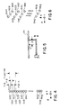
- One method of doing this is to use a piezoelectric bimorph element that is rigidly mounted at one end and is coupled to mirror 26 a distance r beyond the point P as shown in Figure 5.
- the bimorph When voltage is applied to the bimorph, it will bend, rotating the mirror about point P.
- the bimorph receives voltages of zero, V and 2V volts.
- the actual values being determined by the type of piezoelectric device actually employed for the required mirror displacement. Examples of piezoelectric devices suitable for present purposes include those devices manufactured by the Vernitron Division of Morgan Matroc, Inc., Bedford, Ohio.
- a second method of rotating the mirror 26 is to employ the well known galvanometer method.
- This method is not fast as a piezoelectric device, but may be satisfactory for smaller mirrors and slower marking devices.
- Such an arrangement employs permanent magnets disposed on either side of the mirror which is mounted for rotation and which carries a coil. A current passing through the coil causes the mirror to deflect in a direction and by an amount proportional to the magnitude and polarity of the current.
- Other suitable techniques for rotating the mirror include magnetrostrictive elements and for some application servo-mechanisms.
- the directing mirror 26 is movable about the Z-axis through an angle ⁇ in the directions generally indicated by the double-headed arrows 52.
- ⁇ When the directing mirror 26 is rotated ⁇ , as shown in phantom in the counter-clockwise direction, seven additional discrete dots 54 defining upper marking spots (one being shown) are produced onto the surface of the article 46, each dot being disposed vertically in the X-direction above the corresponding reference marking spots 50.
- the path of the light beam from the laser 20a to the marking article 46 when the directing mirror 26 has been rotated ⁇ in a counter-clockwise direction from the reference position is illustrated by the dotted line 60 in Figure 2.
- Figure 4 represents twenty-one dots interleaved from three spot groups 50a-50g, 54a-54g and 56a-56g comprising a single column written by the present apparatus. As previously pointed out, sequential adjacent columns may be written to form a character matrix as the article being marked moves past the laser marking apparatus 10. Each of the dots in the three spot groups 50a-50g, 54a-54g and 56a-56g comprises one point within a distinct character row which is written onto the moving article 46.
- the directing mirror 26 is initially rotated through the angle ⁇ in the counter-clockwise direction relative to the reference position and the lasers 20a-20g are pulsed so as to simultaneously produce the first group of seven upper marking spots 52a-52g corresponding to every third dot of the character matrix column.
- the directing mirror 26 is rotated ⁇ to the reference position and the lasers 20a-20g are pulsed again so as to simultaneously produce the second group of seven reference marking spots 50a-50g corresponding to every third dot of the character matrix column (each being positioned below the corresponding one of the upper marking dots 52a-52g).
- the directing mirror 26 is rotated through another angle ⁇ in the clockwise direction relative to the reference position and the lasers 20a-20g are pulsed once more so as to simultaneously produce the third group of seven lower marking spots 54a-54g corresponding to every third dot of the character matrix column (each being positioned below the corresponding reference marking spots 50a-50g).
- Figure 3 depicts the optical relationship pertaining to the exit lens having a focal length "F".
- the articles 46 are passed adjacent the laser head unit 30 so that the surface 64 to be marked is positioned substantially within the focal plane of the exit lens 40.
- the solid lines 48 represent the light beams from any given laser 20a-20g (i.e., laser 20a) when the directing mirror 26 is in the reference position.
- the dotted lines 60 represent the light beams from the laser 20a when the directing mirror 26 has been rotated the angle ⁇ in the counter-clockwise direction
- the dotted lines 62 represent the light beams from the laser 20a when the directing mirror has been rotated the angle ⁇ in the clockwise direction.
- the light output beam from the laser 20a is highly collimated, it is not absolutely parallel but rather diverges at a known small angle ⁇ which is approximately 4 milliradians. Accordingly, the light from the laser 20a does not focus to a point of infinitesimal size, but to a finite dot or spot of finite proportions.
- the turning mirrors are spaced laterally in the X-direction so as to provide the angular difference ⁇ in the angular path between adjacent beams.
- the angle ⁇ is typically made to be equal to 4 milliradians so as to produce dots that are tangential to each other.
- the value of the angle ⁇ has been chosen in the present invention to be equal to three times ⁇ so that the spot separation of adjacent dots are three dot diameters apart as shown in Figure 4.
- the angle between adjacent beams is selected to be 3 x 4 milliradians or 12 milliradians.
- the directing mirror 26 In order to move the dots up or down by one dot diameter the directing mirror 26 is required to move only ⁇ 1/6 ⁇ or ⁇ 1/6 (3 x 4 milliradians). This angular movement of amounts to only ⁇ 2 milliradians. Assuming that the path from the directing mirror 26 to the exit lens 40 is 30 inches and that the path from the directing mirror 26 to the turning mirrors is 40 inches, it can be shown that the movement at the exit lens 40 is only ⁇ 0.120 inches. Thus, the diameter of the exit lens 40 is required to be only slightly larger in diameter than the lens in the ′722 patent.
- the exterior directing mirror 36 may be rotated rather than the interior directing mirror 26. This may be preferred in as much as mirror 36 will ordinarily be much smaller than mirror 26 and therefore capable of being rotated more quickly.
- the required length of each of the mirrors is a function of its distance from the exit lens 40. The greater the distance, the larger the lens required to redirect the beams. Thus, mirror 26 may need to be on the order of four times the length of mirror 36 (although the mirrors are of the same height).
- the size of the mirrors is important in producing a commercially viable device. Depending on the size of the device it may be necessary to reduce the size of the mirrors 26 and/or 36. This can be accomplished by employing a first beam focusing lens 90 in front of the mirror to converge the beams into a smaller pattern at the mirror surface; and a second condensing lens 92 after the mirror to re-establish the initial beam alignment. This is illustrated in figure 3A. Specifically, lens 90 converges the incoming beams to a much smaller area in its focal plane so that a smaller mirror 26 may be used, (for example 0.5 ⁇ instead of 5 ⁇ ). Lens 92 has the same focal length F as lens 90 and restores the laser beam to their original paths (although inverted). The lens 90 and 92 are preferably cylindrical lens so that converging occurs only in the X-Y plane and not in the Z direction.
- a compensation device 72 is provided to accomplish this correct lateral alignment.
- the compensation device may be chosen depending upon the particular arrangement for its incorporation into the invention. If, for example, rotation is accomplished at mirror 26 conveyor compensation may be accomplished at mirror 36. In that event, any of the techniques previously described for rotating the mirrors can be employed. In particular, a bimorph piezoelectric device or a galvanometric movement can be used to rotate mirror 36 to accomplish correct lateral alignment to form a single column of 21 dots as shown in Figure 4.
- the amount of compensation is, of course, a function of the velocity of the conveyor carrying the items being marked. This information is known and in an open loop embodiment the conveyor speed is simply calculated and used to control the firing sequence for the lasers and the bimorphs.
- a closed loop system would employ a typical micro-processor based programmable controller in which an optical sensor or other feedback element would provide information on any variation in conveyor speed and permit adjustment of the mirrors and laser operation accordingly.
- the present invention provides an improved laser marker apparatus for marking indicia to a substrate in which the number of dot positions in a vertical column is increased.
- the present laser marker apparatus includes a directing mirror which is rotatable so as to produce three columns of spots on the substrate. Each of the three column has seven spots so as to produce a 21-dot high vertical column corresponding to a single column of a character matrix to be marked, thereby producing a higher resolution.
- the substrate to be marked is conveyed by a stepper motor drive so that during marking the substrate is motionless, than no lateral compensation is required to form the interleaved, extended column of dots.
- a stepper motor drive so that during marking the substrate is motionless, than no lateral compensation is required to form the interleaved, extended column of dots.
- other types of lasers may be used and the number may be varied (such as 7 lasers to produce 14 dot columns with only a single displacement of the directing mirror or 3 lasers to produce 12 dot columns with 3 displacements of the directing mirror).
- directing mirror 26 is of the modified construction.
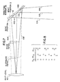
- directing mirror 26 includes a plurality of discrete mirror surfaces 100, interconnected by thin portions 102 thereby to define a slotted back surface as shown in Figure 7.
- This construction permits bending of the mirror 26 as will be hereafter described to change the angular orientation of the discrete surfaces 100. Bending occurs only in the slot or thin portions between the surfaces 100.
- a bendable directing mirror permits selection of the resolution to be produced by the marking device. For example, assuming that there are seven mirror surfaces 100 and seven corresponding lasers which are aimed at these surfaces, it is possible to increase the resolution of the column from seven dots to twenty-one dots (assuming a four mrad separation for adjacent beams). As previously explained, it is necessary to increase the beam spacing from 4 milliradians to 12 milliradians to provide space for interleaving the spots. This is accomplished by bending the directing mirror in the Figure 7 embodiment. Thus, the angular difference from face 1 to face 7 would increase from zero milliradians (straight position) to twenty-four milliradians.
- each beam reflects off a separate one of the mirror faces 100 onto the exit lens 40.
- the directing mirror 26 is stationary, this arrangement will produce one spot for each laser or in a shorthand notation, a 7/7 array. If the angular difference of each beam is four milliradians, as discussed previously, the dots will touch.
- the mirror 26 It is possible to bend the mirror 26 to move the reflecting surfaces 100 from the positions shown in solid to the dashed positions. This, of course, will increase the angular difference between the faces. As shown by dashed lines 104′ and 106′, this alters the beam paths of all but the center face of the turning mirror 26, which remains constant. In this case, the beam paths have been spread to provide additional separation between each dot.
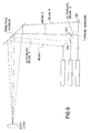
- the directing mirror 26 is then rotated by device 58 to create additional spots. As shown in Figure 8, the laser beams are pulsed to produce a series of dots spaced sufficiently to permit rotation of the mirror 26 to a second position. Additional pulsing produces an additional set of dots, resulting in fourteen dots from seven lasers. Of course, if the turning mirror is bent still further, it is possible to separate the dots by three dot diameters and, as previously described in connection with Figures 4 and 6, to produce a twenty-one dot array from seven lasers by rotating the mirror three times.
- turning mirror 26 in position 1 (the solid line position), turning mirror 26 will produce a linear array in which each dot contacts its adjacent dot if the angular difference between each mirror face is the same as the dot diameter. This may be referred to as a one-to-one resolution mode.
- the turning mirror 26 is bent. In the bent position (the dashed lines), the dots are spaced far enough apart to permit the interleaving of dots therebetween by rotating the mirror 26 while maintaining it in its bent position.
- a two-to-one or three-to-one resolution mode may be obtained, producing either fourteen or twenty-one dots for a seven laser system.
- the bending of mirror 26 can be accomplished in much the same way as the rotation of the mirror. That is, piezoelectric devices may be used to provide the bending force responsive to a control signal applied thereto as illustrated in Figure 5.
- FIG. 9 through 12 a further embodiment is illustrated.
- the turning mirrors 24a through g are fixedly secured to the device and resolution is altered by means of the rotation of the directing mirrors 26 or 36.
- the turning mirrors, three of which are illustrated can have alternate positions. These alternate positions are shown by the dashed lines. In their solid line positions, lasers 2 and 3 create beams 2 and 3 having a first spacing (4 mrad for example).
- Movement of the turning mirrors to the dashed line positions produces alternate beam paths which can be used to vary the spacing between to change resolution from one-to-one to other resolutions, such as two-to-one or three-to-one.
- the directing mirror need not rotate as a seven high matrix will be produced.
- the directing mirror must move.
- the seven laser array is schematically illustrated to show the seven beam paths going down as the drawing is viewed after reflection off the turning mirrors 124a through g. This illustrates the one-to-one mode.
- FIG 11 there is illustrated a two-to-one arrangement in which the seven lasers and seven turning mirrors provide fourteen dots.
- the beam paths are spaced apart which is accomplished by moving the turning mirrors, as illustrated in Figure 9, from the solid positions to the dashed positions.
- Each of the mirrors, except the mirror associated with laser 1 must be moved to change the beam spacing to permit the interleaving of spots.
- the turning mirror associated with laser 1 will produce beam paths 0 and 1 and thus two dots are produced.
- laser 2 and its associated turning mirror will produce beam paths 2 and 3 and so on for the remaining lasers in the array.
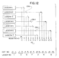
- FIG 12 an alternate implementation of the two-to-one mode of operation is illustrated.
- the turning mirrors associated with lasers 1, 3, 5 and 7 remain in the same positions as for the one-to-one mode of operation.
- the turning mirrors have two alternate positions. In the first position, they are aligned as shown in Figure 10. In a second position, indicated by the arrows, the turning mirrors are moved to create the additional beam paths for dot numbers 8 through 13 in a two-to-one operation mode.
- dots 0 and 1 are produced by laser 1; dots 2 and 3 by laser 3; dots 4 and 5 by laser 5; dots 6 and 7 by laser 7; dots 8 and 9 by laser 2; dots 10 and 11 by laser 4 and dots 12 and 13 by laser 6.
Landscapes
- Physics & Mathematics (AREA)
- Optics & Photonics (AREA)
- Engineering & Computer Science (AREA)
- Plasma & Fusion (AREA)
- Mechanical Engineering (AREA)
- General Physics & Mathematics (AREA)
- Theoretical Computer Science (AREA)
- Laser Beam Processing (AREA)
- Laser Beam Printer (AREA)
Applications Claiming Priority (4)
| Application Number | Priority Date | Filing Date | Title |
|---|---|---|---|
| US07/775,495 US5229574A (en) | 1991-10-15 | 1991-10-15 | Print quality laser marker apparatus |
| US775495 | 1991-10-15 | ||
| US07/827,382 US5229573A (en) | 1991-10-15 | 1992-01-29 | Print quality laser marker apparatus |
| US827382 | 2001-04-04 |
Publications (3)
| Publication Number | Publication Date |
|---|---|
| EP0538044A2 true EP0538044A2 (fr) | 1993-04-21 |
| EP0538044A3 EP0538044A3 (en) | 1993-08-18 |
| EP0538044B1 EP0538044B1 (fr) | 1997-02-05 |
Family
ID=27119057
Family Applications (1)
| Application Number | Title | Priority Date | Filing Date |
|---|---|---|---|
| EP92309431A Expired - Lifetime EP0538044B1 (fr) | 1991-10-15 | 1992-10-15 | Appareil de marquage par laser avec une qualité d'impression améliorée |
Country Status (5)
| Country | Link |
|---|---|
| US (1) | US5229573A (fr) |
| EP (1) | EP0538044B1 (fr) |
| JP (1) | JPH05237675A (fr) |
| CA (1) | CA2080095C (fr) |
| DE (1) | DE69217324T2 (fr) |
Cited By (8)
| Publication number | Priority date | Publication date | Assignee | Title |
|---|---|---|---|---|
| EP0623887A1 (fr) * | 1993-05-05 | 1994-11-09 | International Business Machines Corporation | Système continu de marquage avec code à barres |
| WO1998011495A1 (fr) * | 1996-09-11 | 1998-03-19 | Domino Printing Sciences Plc | Dispositif a lasers |
| ES2112756A1 (es) * | 1995-05-23 | 1998-04-01 | Macsa Id Sa | Sistema de marcacion de puntos con laser. |
| ES2115533A1 (es) * | 1996-04-26 | 1998-06-16 | Macsa Id Sa | Sistema de perforacion dinamico por laser. |
| DE19748724A1 (de) * | 1997-11-05 | 1999-05-06 | Bundesdruckerei Gmbh | Verfahren und Vorrichtung zur Personalisierung von Wertdokumenten |
| ES2140341A1 (es) * | 1998-03-17 | 2000-02-16 | Macsa Id Sa | Sistema de marcaje laser. |
| WO2000053364A1 (fr) * | 1999-03-09 | 2000-09-14 | Siemens Aktiengesellschaft | Procede et dispositif de structuration de pieces au laser |
| WO2001036208A3 (fr) * | 1999-11-18 | 2002-02-28 | Orga Kartensysteme Gmbh | Procede pour appliquer des informations en couleur sur un objet |
Families Citing this family (32)
| Publication number | Priority date | Publication date | Assignee | Title |
|---|---|---|---|---|
| DE3535897A1 (de) * | 1984-12-14 | 1986-06-19 | WOCO Franz-Josef Wolf & Co, 6483 Bad Soden-Salmünster | Federkoerper und verfahren zu seiner herstellung |
| DE3901898A1 (de) * | 1989-01-23 | 1990-07-26 | Wolf Woco & Co Franz J | Flaechenlager und verfahren zu seiner herstellung |
| CZ141893A3 (en) * | 1991-01-17 | 1993-12-15 | United Distillers Plc | Process and apparatus for marking a moving object |
| DE4234844C5 (de) * | 1992-10-15 | 2007-08-30 | Schaeffler Kg | Dämpfungsvorrichtung für Linear-Wälzlager-Führungen |
| US5294774A (en) * | 1993-08-03 | 1994-03-15 | Videojet Systems International, Inc. | Laser marker system |
| US5767477A (en) * | 1994-03-23 | 1998-06-16 | Domino Printing Sciences Plc | Laser marking apparatus for marking twin-line messages |
| US6791592B2 (en) | 2000-04-18 | 2004-09-14 | Laserink | Printing a code on a product |
| JP4636672B2 (ja) * | 2000-11-15 | 2011-02-23 | 大日本印刷株式会社 | レーザマーキング装置及びレーザマーク媒体 |
| US20050088510A1 (en) * | 2003-10-24 | 2005-04-28 | Shlomo Assa | Low angle optics and reversed optics |
| JP2005144487A (ja) * | 2003-11-13 | 2005-06-09 | Seiko Epson Corp | レーザ加工装置及びレーザ加工方法 |
| US7046267B2 (en) * | 2003-12-19 | 2006-05-16 | Markem Corporation | Striping and clipping correction |
| US7394479B2 (en) | 2005-03-02 | 2008-07-01 | Marken Corporation | Pulsed laser printing |
| US8502111B2 (en) | 2007-04-12 | 2013-08-06 | Charles L. Henderson | Laser woodworking machine |
| US8212178B1 (en) | 2009-09-28 | 2012-07-03 | Klein Tools, Inc. | Method and system for marking a material using a laser marking system |
| EP2564976B1 (fr) | 2011-09-05 | 2015-06-10 | ALLTEC Angewandte Laserlicht Technologie Gesellschaft mit beschränkter Haftung | Appareil de marquage avec au moins un laser à gas et un dissipateur de chaleur |
| EP2565673B1 (fr) | 2011-09-05 | 2013-11-13 | ALLTEC Angewandte Laserlicht Technologie Gesellschaft mit beschränkter Haftung | Dispositif et procédé pour marquer un objet au moyen d'un rayon laser |
| EP2564971B1 (fr) | 2011-09-05 | 2015-08-26 | ALLTEC Angewandte Laserlicht Technologie Gesellschaft mit beschränkter Haftung | Appareil de marquage avec plusieurs lasers et un jeu de déflecteurs |
| ES2450467T3 (es) | 2011-09-05 | 2014-03-24 | ALLTEC Angewandte Laserlicht Technologie Gesellschaft mit beschränkter Haftung | Dispositivo láser y procedimiento de generación de luz láser |
| EP2564970B1 (fr) | 2011-09-05 | 2015-08-26 | ALLTEC Angewandte Laserlicht Technologie Gesellschaft mit beschränkter Haftung | Dispositif de marquage pour objet avec lumière de marquage avec plusieurs modules utilisant différentes technologies pour émettre la lumière |
| EP2565995B1 (fr) | 2011-09-05 | 2013-12-18 | ALLTEC Angewandte Laserlicht Technologie Gesellschaft mit beschränkter Haftung | Dispositif laser à gaz avec un réservoir de gaz |
| EP2565998A1 (fr) | 2011-09-05 | 2013-03-06 | ALLTEC Angewandte Laserlicht Technologie Gesellschaft mit beschränkter Haftung | Dispositif laser à gaz en anneau |
| EP2564972B1 (fr) * | 2011-09-05 | 2015-08-26 | ALLTEC Angewandte Laserlicht Technologie Gesellschaft mit beschränkter Haftung | Appareil de marquage avec plusieurs lasers et des moyens de déflection et de focalisation pour chaque faisceau lser |
| DK2564973T3 (en) * | 2011-09-05 | 2015-01-12 | Alltec Angewandte Laserlicht Technologie Ges Mit Beschränkter Haftung | Marking apparatus having a plurality of lasers and a kombineringsafbøjningsindretning |
| ES2530070T3 (es) * | 2011-09-05 | 2015-02-26 | ALLTEC Angewandte Laserlicht Technologie Gesellschaft mit beschränkter Haftung | Aparato de marcado con una pluralidad de láseres y conjuntos ajustables individualmente de medios de desviación |
| EP2565996B1 (fr) | 2011-09-05 | 2013-12-11 | ALLTEC Angewandte Laserlicht Technologie Gesellschaft mit beschränkter Haftung | Dispositif laser doté d'une unité laser, et récipient pour fluides pour moyen de refroidissement de ladite unité laser |
| ES2452529T3 (es) | 2011-09-05 | 2014-04-01 | ALLTEC Angewandte Laserlicht Technologie Gesellschaft mit beschränkter Haftung | Dispositivo láser y procedimiento para marcar un objeto |
| EP2564974B1 (fr) | 2011-09-05 | 2015-06-17 | ALLTEC Angewandte Laserlicht Technologie Gesellschaft mit beschränkter Haftung | Appareil de marquage avec une pluralité de lasers gaz ayant des tubes résonateurs et des déflecteurs ajustables individuellement |
| US10745773B2 (en) * | 2011-12-27 | 2020-08-18 | Jfe Steel Corporation | Device to improve iron loss properties of grain-oriented electrical steel sheet |
| FI20135385A7 (fi) * | 2013-04-18 | 2014-10-19 | Cajo Tech Oy | Metallipintojen värimerkintä |
| US10583668B2 (en) | 2018-08-07 | 2020-03-10 | Markem-Imaje Corporation | Symbol grouping and striping for wide field matrix laser marking |
| DE102018219619A1 (de) * | 2018-11-16 | 2020-06-04 | Volkswagen Aktiengesellschaft | Verfahren zum Schneiden von einem kontinuierlichen Batterieelektrodenmaterial zur Herstellung von Batterieelektroden sowie eine Batterieelektrode |
| US12232680B2 (en) | 2022-08-24 | 2025-02-25 | Haier Us Appliance Solutions, Inc. | Clean dish verification using a camera assembly in a dishwasher appliance |
Family Cites Families (2)
| Publication number | Priority date | Publication date | Assignee | Title |
|---|---|---|---|---|
| GB2133352B (en) * | 1983-01-13 | 1985-09-11 | Laser Applic Limited | A laser marking system |
| US4652722A (en) * | 1984-04-05 | 1987-03-24 | Videojet Systems International, Inc. | Laser marking apparatus |
-
1992
- 1992-01-29 US US07/827,382 patent/US5229573A/en not_active Expired - Fee Related
- 1992-10-07 CA CA002080095A patent/CA2080095C/fr not_active Expired - Fee Related
- 1992-10-15 DE DE69217324T patent/DE69217324T2/de not_active Expired - Fee Related
- 1992-10-15 JP JP4277532A patent/JPH05237675A/ja active Pending
- 1992-10-15 EP EP92309431A patent/EP0538044B1/fr not_active Expired - Lifetime
Cited By (13)
| Publication number | Priority date | Publication date | Assignee | Title |
|---|---|---|---|---|
| US5521709A (en) * | 1993-05-05 | 1996-05-28 | International Business Machines Corporation | Continuous barcode marking system |
| EP0623887A1 (fr) * | 1993-05-05 | 1994-11-09 | International Business Machines Corporation | Système continu de marquage avec code à barres |
| ES2112756A1 (es) * | 1995-05-23 | 1998-04-01 | Macsa Id Sa | Sistema de marcacion de puntos con laser. |
| ES2115533A1 (es) * | 1996-04-26 | 1998-06-16 | Macsa Id Sa | Sistema de perforacion dinamico por laser. |
| US6421159B1 (en) | 1996-09-11 | 2002-07-16 | The Domino Corporation | Multiple beam laser marking apparatus |
| WO1998011495A1 (fr) * | 1996-09-11 | 1998-03-19 | Domino Printing Sciences Plc | Dispositif a lasers |
| DE19748724A1 (de) * | 1997-11-05 | 1999-05-06 | Bundesdruckerei Gmbh | Verfahren und Vorrichtung zur Personalisierung von Wertdokumenten |
| DE19748724B4 (de) * | 1997-11-05 | 2008-09-25 | Bundesdruckerei Gmbh | Verfahren und Vorrichtung zur Personalisierung von Wertdokumenten |
| ES2140341A1 (es) * | 1998-03-17 | 2000-02-16 | Macsa Id Sa | Sistema de marcaje laser. |
| US6201210B1 (en) | 1998-03-17 | 2001-03-13 | Macsa Id S.A. | Laser marking apparatus with diode laser matrix |
| WO2000053364A1 (fr) * | 1999-03-09 | 2000-09-14 | Siemens Aktiengesellschaft | Procede et dispositif de structuration de pieces au laser |
| WO2001036208A3 (fr) * | 1999-11-18 | 2002-02-28 | Orga Kartensysteme Gmbh | Procede pour appliquer des informations en couleur sur un objet |
| US7158145B1 (en) | 1999-11-18 | 2007-01-02 | Orga Systems Gmbh | Method for applying colored information on an object |
Also Published As
| Publication number | Publication date |
|---|---|
| JPH05237675A (ja) | 1993-09-17 |
| EP0538044A3 (en) | 1993-08-18 |
| DE69217324T2 (de) | 1997-06-12 |
| US5229573A (en) | 1993-07-20 |
| EP0538044B1 (fr) | 1997-02-05 |
| CA2080095C (fr) | 1999-12-21 |
| DE69217324D1 (de) | 1997-03-20 |
| CA2080095A1 (fr) | 1993-04-16 |
Similar Documents
| Publication | Publication Date | Title |
|---|---|---|
| EP0538044B1 (fr) | Appareil de marquage par laser avec une qualité d'impression améliorée | |
| US5229574A (en) | Print quality laser marker apparatus | |
| USRE35446E (en) | Laser marker system | |
| EP0609205B1 (fr) | Appareil d'ecriture matricielle par points au moyen d'un laser a emission continue | |
| EP0157546B1 (fr) | Appareil de marquage par laser | |
| EP0460889B1 (fr) | Système de suivi de piste optique | |
| US4838631A (en) | Laser beam directing system | |
| US5166944A (en) | Laser beam scanning apparatus and method | |
| US5185676A (en) | Beam scanning apparatus and apparatus for writing image information | |
| US6605799B2 (en) | Modulation of laser energy with a predefined pattern | |
| US5767477A (en) | Laser marking apparatus for marking twin-line messages | |
| JP2526717B2 (ja) | レ―ザ加工装置 | |
| JPS6178587A (ja) | 対象物の表面を非接触に変化させるための装置 | |
| US4937593A (en) | Print head position control system | |
| GB2310504A (en) | Laser marking apparatus and methods | |
| JPH08500059A (ja) | レーザーまたはこれに関連する改良 | |
| US4751525A (en) | Scanning system and method of scanning | |
| JP3546532B2 (ja) | 光スキャナ装置 | |
| US5002375A (en) | Variable pel density print head for electrophotographic printers | |
| US4429948A (en) | Optical alignment compensation | |
| WO2001080160A2 (fr) | Impression d'un code sur un produit | |
| EP0976002A1 (fr) | Systeme de deplacement d'un faisceau laser, par exemple systeme de marquage au laser | |
| JPH03257939A (ja) | レーザビーム制御装置 | |
| JPH0480708A (ja) | 光線走査装置 | |
| JPH05164978A (ja) | マルチビーム記録装置 |
Legal Events
| Date | Code | Title | Description |
|---|---|---|---|
| PUAI | Public reference made under article 153(3) epc to a published international application that has entered the european phase |
Free format text: ORIGINAL CODE: 0009012 |
|
| AK | Designated contracting states |
Kind code of ref document: A2 Designated state(s): DE ES FR GB IT |
|
| PUAL | Search report despatched |
Free format text: ORIGINAL CODE: 0009013 |
|
| AK | Designated contracting states |
Kind code of ref document: A3 Designated state(s): DE ES FR GB IT |
|
| 17P | Request for examination filed |
Effective date: 19940209 |
|
| GRAG | Despatch of communication of intention to grant |
Free format text: ORIGINAL CODE: EPIDOS AGRA |
|
| 17Q | First examination report despatched |
Effective date: 19960426 |
|
| GRAH | Despatch of communication of intention to grant a patent |
Free format text: ORIGINAL CODE: EPIDOS IGRA |
|
| GRAH | Despatch of communication of intention to grant a patent |
Free format text: ORIGINAL CODE: EPIDOS IGRA |
|
| GRAA | (expected) grant |
Free format text: ORIGINAL CODE: 0009210 |
|
| AK | Designated contracting states |
Kind code of ref document: B1 Designated state(s): DE ES FR GB IT |
|
| PG25 | Lapsed in a contracting state [announced via postgrant information from national office to epo] |
Ref country code: IT Free format text: LAPSE BECAUSE OF FAILURE TO SUBMIT A TRANSLATION OF THE DESCRIPTION OR TO PAY THE FEE WITHIN THE PRE;WARNING: LAPSES OF ITALIAN PATENTS WITH EFFECTIVE DATE BEFORE 2007 MAY HAVE OCCURRED AT ANY TIME BEFORE 2007. THE CORRECT EFFECTIVE DATE MAY BE DIFFERENT FROM THE ONE RECORDED.SCRIBED TIME-LIMIT Effective date: 19970205 Ref country code: FR Effective date: 19970205 Ref country code: ES Free format text: THE PATENT HAS BEEN ANNULLED BY A DECISION OF A NATIONAL AUTHORITY Effective date: 19970205 |
|
| REF | Corresponds to: |
Ref document number: 69217324 Country of ref document: DE Date of ref document: 19970320 |
|
| EN | Fr: translation not filed | ||
| PLBE | No opposition filed within time limit |
Free format text: ORIGINAL CODE: 0009261 |
|
| 26N | No opposition filed | ||
| PGFP | Annual fee paid to national office [announced via postgrant information from national office to epo] |
Ref country code: GB Payment date: 19991021 Year of fee payment: 8 |
|
| PGFP | Annual fee paid to national office [announced via postgrant information from national office to epo] |
Ref country code: DE Payment date: 19991028 Year of fee payment: 8 |
|
| PG25 | Lapsed in a contracting state [announced via postgrant information from national office to epo] |
Ref country code: GB Free format text: LAPSE BECAUSE OF NON-PAYMENT OF DUE FEES Effective date: 20001015 |
|
| GBPC | Gb: european patent ceased through non-payment of renewal fee |
Effective date: 20001015 |
|
| PG25 | Lapsed in a contracting state [announced via postgrant information from national office to epo] |
Ref country code: DE Free format text: LAPSE BECAUSE OF NON-PAYMENT OF DUE FEES Effective date: 20010703 |