EP0538111A1 - Verfahren zur Durchführung eines synthesierten Referenzbildes und Vorrichtung zur Ausführung des Verfahrens - Google Patents
Verfahren zur Durchführung eines synthesierten Referenzbildes und Vorrichtung zur Ausführung des Verfahrens Download PDFInfo
- Publication number
- EP0538111A1 EP0538111A1 EP92402783A EP92402783A EP0538111A1 EP 0538111 A1 EP0538111 A1 EP 0538111A1 EP 92402783 A EP92402783 A EP 92402783A EP 92402783 A EP92402783 A EP 92402783A EP 0538111 A1 EP0538111 A1 EP 0538111A1
- Authority
- EP
- European Patent Office
- Prior art keywords
- image
- characteristic elements
- real
- images
- inspected
- Prior art date
- Legal status (The legal status is an assumption and is not a legal conclusion. Google has not performed a legal analysis and makes no representation as to the accuracy of the status listed.)
- Withdrawn
Links
Images



Classifications
-
- G—PHYSICS
- G06—COMPUTING OR CALCULATING; COUNTING
- G06T—IMAGE DATA PROCESSING OR GENERATION, IN GENERAL
- G06T7/00—Image analysis
- G06T7/0002—Inspection of images, e.g. flaw detection
- G06T7/0004—Industrial image inspection
- G06T7/001—Industrial image inspection using an image reference approach
-
- G—PHYSICS
- G06—COMPUTING OR CALCULATING; COUNTING
- G06T—IMAGE DATA PROCESSING OR GENERATION, IN GENERAL
- G06T2207/00—Indexing scheme for image analysis or image enhancement
- G06T2207/30—Subject of image; Context of image processing
- G06T2207/30108—Industrial image inspection
- G06T2207/30148—Semiconductor; IC; Wafer
Definitions
- the present invention relates to a method and its implementation device making it possible to produce a synthetic image used, when comparing images, as a reference image.
- Such a method finds numerous applications in the field of industrial inspection where it is sought to control an object by comparison of the image of said object with the synthesized reference image.
- this invention can be applied to the verification of integrated circuits manufactured from an industrial production line.
- a process for generating a new graphic scene by replacing certain graphic patterns is described in document EP-A-0 354 031, filed on August 3, 1989, by XEROX CORPORATION.
- This process consists in carrying out a first step of choosing the graphic patterns which will have to be sought; it then consists in carrying out a second search step, in the graphic scene, of all the occurrences of the graphic patterns chosen previously; this method finally consists of a third step of replacing, in the graphic scene, these graphic patterns by other patterns generally coming from a library.
- Such a method cannot be applied to the generation of images intended to serve as a reference during an inspection by comparison of objects such as integrated circuits. Indeed, the comparison of such images with images of real scenes is not precise enough to detect very small defects in the objects to be inspected.
- the method described above therefore does not make it possible to generate a reference image sufficiently close to a real image to show no discontinuity, in particular, in the variations in gray levels of the image.
- the object of the present invention is to remedy this drawback. Indeed, it proposes a method making it possible to replace, on a binary image obtained by transformation of design data coming from a CAD database, the graphic patterns (representing the characteristic elements of the object) by real images of said elements characteristics.
- the method proposes to carry out a mesh change consisting in effecting the transition from the characteristic elements in camera mesh to characteristic elements in CAD mesh. It also proposes a precise centering of the characteristic elements making it possible to ensure continuity of the reference image, in particular in the variations of gray levels.
- the method consists in performing, after operation (d), an operation (e) for storing the reference image.
- the descriptive information is preferably used in the form of a binary image in order to facilitate the processing, in particular the processing carried out during operations (a) and (b).
- operation (d) advantageously consists in replacing, for each position information, the characteristic elements represented on the binary image by the real images of the corresponding characteristic elements.
- the repositioning could also be carried out directly on an image free of information (that is to say an empty table).
- the method further comprises an operation of resampling the real images of the characteristic elements obtained in (c).
- this resampling includes a centering calculation operation on the real images of the characteristic elements. It further comprises an operation for calculating a width difference between the characteristic element represented on the binary image and its corresponding real image.
- operation (b) comprises a sub-operation for establishing a list in which the characteristic elements are associated respectively with their positions.
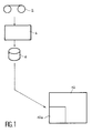
- the descriptive data of the integrated circuit to be inspected are stored in means 2 for storing information, such as a magnetic tape or a cassette.
- This descriptive data is C.A.O. (Computer Aided Design), that is to say data recorded in a compact form optimizing the volume necessary for their storage (memorization).
- the characteristic elements of an integrated circuit are, for example, one or more pixels representative of the gray level of the background of the circuit (called uniform areas of a first type), one or more pixels representative of the gray level of the patterns of the circuit (called a uniform zone of a second type), pattern corners, transitions (i.e. elements of the border between the background and the pattern), particular elements such as memory cells, holes contact, etc.
- the pixels representing the gray levels correspond to the image elements of the real images.
- the computer 4 draws up lists in which a characteristic element generally represented by a code is associated with a position. When this characteristic element is present several times in the integrated circuit, it is also present several times in the list, in which it is associated with each of its positions. These lists are saved on a hard disk 6 to which the computer 4 can access at any time.
- This inspection system 12 makes it possible to carry out the operations (c) to (e) of the process according to the invention, a process which will be described below.
- FIG. 2 shows the functional diagram describing the various operations carried out during the implementation of the method according to the invention.
- phase 100 of C.A.O. data preprocessing essentially consists of translating C.A.O. into binary image data.
- the data from C.A.O. are "compact" data, that is to say, in particular, that each element of the C.A.O. is described only once in said database, regardless of the number of times it is present in the integrated circuit.
- These data from C.A.O. are therefore translated as a binary image, where the elements appear as many times as they appear on the integrated circuit. This binary image has the advantage of representing entirely, on a display screen, the integrated circuit.
- the preprocessing phase 100 comprises a first step 102 of recording, in the CAD database, descriptive information of the circuit contained in a mass memory such as a magnetic tape 2 and any information already known and stored by example in hard drive 6.
- CAD data are advantageously retranslated, that is to say transformed, in block 104, in the form of a binary image in order to facilitate subsequent treatments.
- the image resolution of this binary image, obtained in 104 is the same as that of the CAD database. Indeed, to limit the loss of information that can occur during this kind of transformation, we synthesize said binary image. in the CAD mesh corresponding to the description system of the integrated circuit.
- This C.A.O. may for example be equal to 0.1 ⁇ m x 0.1 ⁇ m or, to 0.05 ⁇ m x 0.0 5 ⁇ m, when the integrated circuit is very dense, that is to say when it has many characteristic elements.
- the next step consists in determining the characteristic elements of the integrated circuit to be inspected.
- the optional step 107 consists in measuring the theoretical width of a particular pattern chosen in any way from the binary image. This measurement, compared later to the actual width of a pattern of the same type, will make it possible, as will be seen later, to determine the difference between these two values.
- step 106 this is an observation, for example by a user, of the various characteristic elements such as patterns, parts of patterns or group of patterns, present on the integrated circuit.
- the characteristic elements are defined respectively in the form of a binary mask and information relating to the position of said characteristic elements thus coded is extracted from the binary image.
- This detection of the position of the characteristic elements takes place on the theoretical binary image obtained at 104, completely free of noise. It therefore consists of a simple decoding of the configurations corresponding to said characteristic elements.
- the binary image is scanned using a window, with a few pixels of sides.
- the content of the window is correlated with the characteristic elements coded in the form of masks.
- the content of the window corresponds to one of the characteristic elements sought.
- the window is generally the same size as the mask of the characteristic element being searched.
- an image of types is created, that is to say an image representative of the position of the typical characteristic elements in the binary image (for example codes distributed in a table).
- This position information is obtained with an accuracy equal to the resolution of the design database, this resolution generally being greater than the resolution of a real image, for which said resolution is given by the size of the pixels of the camera used. for the acquisition of said real image.
- This detection is therefore carried out with subpixel precision in the mesh of the camera.
- Block 108 of Figure 2 represents the data compression step in which a list of types is established. This list contains the characteristic elements and their associated positions.
- This list as well as the theoretical width of a pattern are stored for example in the hard disk 6, from which the information contained in said list, will be withdrawn at the time of phase 300 of synthesis.
- Coding the type image in the form of a list makes it possible to condense the information contained in said type image and therefore to reduce the volume of data to be stored during the preprocessing phase. This condensation of information advantageously makes it possible to reduce the time for transferring said information.
- this list can be obtained directly after the step 104 of detecting the position of the characteristic elements; passing through a type image is not compulsory and depends on the choice of processing used to obtain the standard list from step 104.
- the learning phase is represented, in FIG. 2, by the block 200. This phase relates to the acquisition of the real images of the characteristic elements.
- the user takes therefrom portions of images corresponding to the characteristic elements.
- image portions can be individual or grouped pixels, line portions, column portions, etc.
- portions of images are chosen to be free from defects.
- the user selects the circuit to be used for this phase, by means, for example, of a microscope. It is also this user who chooses, on this circuit, the portions of the image used in the rest of the processing so that these allow the realization of a reference image for all circuits to be inspected comprising elements of the same type.
- the acquisition of the real image is carried out during a step 202.
- the resolution of this real image is identical to the resolution of the image sensor (or camera).
- the step of taking the samples which follows the step 202, comprises a step 204 and possibly a step 206 respectively of taking the actual samples of the characteristic elements and measuring the real width of the pattern defined previously in step 107.
- the patterns of the integrated circuit can be over or under engraved. Indeed, to produce the integrated circuits, microlithography methods are applied which may experience fluctuations in the size of the patterns. These fluctuations are due to engraving. An over engraved pattern will be smaller than the reference size of the corresponding pattern in the binary image. An insufficiently engraved pattern will be larger than said reference size.
- the comparison between the actual width of the pattern, determined in step 206, and the theoretical width of this pattern, determined in step 107 and stored in the disc 6, makes it possible to have the difference (or offset) between these two values.
- This comparison step is carried out in step 208 described later.
- the user uses for example the inspection system in a semi-automatic mode.
- This inspection system allows said user to move an observation field on the surface of the integrated circuit. It thus analyzes the constitution of said circuit in order to choose the characteristic elements which are best suited. In other words, it searches for a fault-free circuit field containing the chosen characteristic elements. The real image of this field is then acquired and named "learning image”.
- these samples generally do not have a precise place in the training image, since the camera allowing the acquisition of the images does not have a fixed position, that is to say a position determined relative to to the integrated circuit.
- the corners and transitions, among others, are in any position relative to the mesh of the camera.
- a resampling operation 208 is then introduced in the learning phase 200.
- This resampling allows the samples to be shifted taking into account the centering calculation carried out on the actual samples of the transitions and corners, as well as the measurement of the difference in over or under-etching carried out during this same step.
- this centering calculation consists in determining the difference -between the arbitrary position of the characteristic elements and a determined position called centered, in the mesh of the sensor. This difference is then added algebraically to the over or undercut offset.
- operation 208 performs the transition from camera mesh samples to C.A.O. by a second resampling.
- resampling can be carried out, in one or more stages, according to several known methods, such as linear interpolation.
- the actual images of the characteristic elements are then advantageously recorded in a library, such as a mass memory which may be the disk 6, the memory of the system 12 described previously or the memory of a card described later. Said images can be searched in this library and used when synthesizing a reference image. When updating a reference image after variations in the appearance of the circuit corresponding to said image, the actual images recorded are replaced by those taken from the new circuit.
- a library such as a mass memory which may be the disk 6, the memory of the system 12 described previously or the memory of a card described later.
- the phase 300 of synthesis consists in replacing in the image being synthesized, that is to say in the image of types, the values of the pixels by new values corresponding to those of the real samples of the characteristic elements coming from the learning phase 200. This replacement operation with the actual samples is carried out for each of the positions detected in phase 100 of preprocessing.
- step 310 of recovering the list of types consists in searching, in the hard disk 6, for the information contained in said list: a decompression of the data is carried out (namely an inverse operation to that which consists in transform the image of types into a list of types) in order to find the image of types on which we apply, in an operation 320, the real samples determined in 210.
- This application operation 320 consists, by a substitute method, of pasting the samples taken in the training image onto the pixels identified during the operation 106 of determining the characteristic elements.
- a synthesized image is obtained comprising gray levels, like a real image.
- This synthesized image is developed in a C.A.O.
- a last resampling operation 330 makes it possible to modify this last image into an image synthesized in the mesh of the sensor (namely, the camera). This latter resampling can consist, according to one embodiment, of a linear interpolation.
- FIG. 3 shows an example of the various patterns sought during the position detection operation 106.
- This operation 106 consists in identifying, on the binary image obtained in 104, the places of application of the real samples obtained in 210.
- This detection consists in decoding the configurations corresponding to the transitions and the corners.
- dotted area I there is shown, for example, a binary image in which the different corners and transitions are sought.
- this binary image one can locate the corners C14, C9 and C3, the corners CC11 and CC3 complementary to the respective corners C11 and C3.
- a transition has been represented in the form of a transition vector and a corner, in the form of a corner matrix during the "bonding" 320 (also called application) of the real samples, taken and centered during the phase 200 of learning, on the binary image.
- These vectors and matrices are advantageously taken respectively in length and in even sides, so as to easily locate the center of said vector and of said matrix.
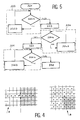
- Zone A of FIG. 4 shows a vector with center v, positioned so that its center v corresponds to the transition of the binary image.
- Zone B of FIG. 4 shows a matrix of center m positioned so that its center m corresponds to the corner of the binary matrix.
- FIG. 5 shows an example of a functional diagram of the operation 320 of applying the real samples (in the case where they consist of uniform zones, transitions and corners), in which one seeks to paste the real samples, taken in the learning phase 200, on the pixels identified during the type detection phase 106.
- an image is obtained in the C.A.O.
- the binary image is transformed into an image of uniform zones in the C.A.O. after application of the loop 322.
- This image is transformed into an image of uniform zones and transitions in the C.A.O. at the end of the loop 324, itself transformed into an image of uniform zones, transitions and corners, in the CAD mesh, after application of the processing loop 326.
- a resampling 330 described above, makes it possible to obtain of the synthesized image in the mesh of the sensor.
- FIG. 6 there is shown an example of a device implementing the method according to the invention.
- This device comprises means 1 for processing images, and means for taking pictures such as a machine 13 for interactive inspection of the integrated circuit 11.
- This integrated circuit 11 to be inspected is arranged on a mechanical table not shown in the figure.
- the inspection machine 13 comprises an inspection subsystem 12, a CCD camera 14 (charge transfer) associated with a microscope 15, an image display card 16 and a unit 18 allowing the user to view the images and make your choices (of image fields, for example). This machine thus allows the acquisition and comparison of images.
- CCD camera 14 charge transfer
- the processing means 1 comprise a computer 4 equipped with a hard disk 6, a reader 2 for magnetic tapes (or, depending on the embodiment chosen, a cassette player) and a coupler 8 ensuring the coupling between the computer 4 and the rapid image processing unit (UTRI) of the inspection subsystem 12 via a bus 20.
- a computer 4 equipped with a hard disk 6, a reader 2 for magnetic tapes (or, depending on the embodiment chosen, a cassette player) and a coupler 8 ensuring the coupling between the computer 4 and the rapid image processing unit (UTRI) of the inspection subsystem 12 via a bus 20.
- UTRI rapid image processing unit
- These processing means 1 also include a 10 C.P.U. (central processing unit).
- the 10 C.P.U. and the computer 4 are dissociated because said computer can be directly integrated into the central calculation of the factory manufacturing the integrated circuits to be inspected.
- the data bus 20 ensures the transmission of information between the image processing means 1 and the inspection machine 13. More precisely, the display card 16, the inspection subsystem 12, the C.P.U. and the coupler 8 are connected to said bus 20.
- the operations 102 to 108, carried out during the pre-treatment phase 100, are processed by the computer 4.
- the following operations which constitute the learning phase 200 are carried out from the display unit 18, the camera 14 and the inspection subsystem 12 which manages in particular the relative movements between the integrated circuit 11 and the camera 14, as well as the acquisition of real images of said integrated circuit.
- the images of the characteristic elements of the circuit 11, that is to say the actual samples obtained, are stored in the card memory 10 CPU where they are sought at the time of the operation 320 of application.
- the list of types stored in the hard disk 6 is transferred to the memory of the card 10 C.P.U.
- the processor of said card 10 performs the operations 320 of applying the characteristic elements.
- the synthesized image thus obtained is transferred to the inspection subsystem 12 where it is used as a reference image during comparisons with the images of integrated circuits to be inspected.
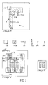
- FIG. 7 shows an example of implementation of the method according to the invention.
- a training image has been represented with its characteristic elements, such as the corner C9, the complementary corner CC9, the vertical transition T1, the complementary horizontal transition TC2, and the pixels of the first type of uniform zone PF and of the second type of uniform zone PM.
- image B of FIG. 7 the image obtained at the time of application of the real samples to the binary image is represented, as a function of the list of positions obtained in the preprocessing phase.
- FIG. 7 undoubtedly allows a better understanding of the method according to the invention. However, this is just a simple example of a sparse circuit.
Landscapes
- Engineering & Computer Science (AREA)
- Quality & Reliability (AREA)
- Computer Vision & Pattern Recognition (AREA)
- Physics & Mathematics (AREA)
- General Physics & Mathematics (AREA)
- Theoretical Computer Science (AREA)
- Image Processing (AREA)
- Image Analysis (AREA)
- Investigating Materials By The Use Of Optical Means Adapted For Particular Applications (AREA)
Applications Claiming Priority (2)
| Application Number | Priority Date | Filing Date | Title |
|---|---|---|---|
| FR9112617 | 1991-10-14 | ||
| FR9112617A FR2682511B1 (fr) | 1991-10-14 | 1991-10-14 | Procede de realisation d'une image de reference synthetisee pour le controle d'objets, et son dispositif de mise en óoeuvre. |
Publications (1)
| Publication Number | Publication Date |
|---|---|
| EP0538111A1 true EP0538111A1 (de) | 1993-04-21 |
Family
ID=9417873
Family Applications (1)
| Application Number | Title | Priority Date | Filing Date |
|---|---|---|---|
| EP92402783A Withdrawn EP0538111A1 (de) | 1991-10-14 | 1992-10-12 | Verfahren zur Durchführung eines synthesierten Referenzbildes und Vorrichtung zur Ausführung des Verfahrens |
Country Status (3)
| Country | Link |
|---|---|
| EP (1) | EP0538111A1 (de) |
| FR (1) | FR2682511B1 (de) |
| IL (1) | IL103343A (de) |
Cited By (2)
| Publication number | Priority date | Publication date | Assignee | Title |
|---|---|---|---|---|
| FR2697930A1 (fr) * | 1992-11-09 | 1994-05-13 | Commissariat Energie Atomique | Procédé de réalisation d'une image de référence synthétisée pour l'inspection d'objets. |
| EP0593183A3 (de) * | 1992-10-16 | 1994-11-17 | Polaroid Corp | System zum Vergleich eines CAD-Bildes mit einem Videobild. |
Citations (2)
| Publication number | Priority date | Publication date | Assignee | Title |
|---|---|---|---|---|
| EP0163264A2 (de) * | 1984-06-01 | 1985-12-04 | General Electric Company | Digitale Subtraktionsangiographie im Gebiet von Interesse |
| EP0354031A2 (de) * | 1988-08-04 | 1990-02-07 | Xerox Corporation | Graphische Bildaufbereitung |
-
1991
- 1991-10-14 FR FR9112617A patent/FR2682511B1/fr not_active Expired - Fee Related
-
1992
- 1992-10-05 IL IL10334392A patent/IL103343A/en not_active IP Right Cessation
- 1992-10-12 EP EP92402783A patent/EP0538111A1/de not_active Withdrawn
Patent Citations (2)
| Publication number | Priority date | Publication date | Assignee | Title |
|---|---|---|---|---|
| EP0163264A2 (de) * | 1984-06-01 | 1985-12-04 | General Electric Company | Digitale Subtraktionsangiographie im Gebiet von Interesse |
| EP0354031A2 (de) * | 1988-08-04 | 1990-02-07 | Xerox Corporation | Graphische Bildaufbereitung |
Non-Patent Citations (1)
| Title |
|---|
| SPIE vol. 1261, 1990, BELLINGHAM US pages 195 - 205 SUSUMU TAKEUCHI ET AL. 'Advanced 5x reticle inspection technologies for ULSI devices' * |
Cited By (4)
| Publication number | Priority date | Publication date | Assignee | Title |
|---|---|---|---|---|
| EP0593183A3 (de) * | 1992-10-16 | 1994-11-17 | Polaroid Corp | System zum Vergleich eines CAD-Bildes mit einem Videobild. |
| FR2697930A1 (fr) * | 1992-11-09 | 1994-05-13 | Commissariat Energie Atomique | Procédé de réalisation d'une image de référence synthétisée pour l'inspection d'objets. |
| EP0597762A1 (de) * | 1992-11-09 | 1994-05-18 | Commissariat A L'energie Atomique | Verfahren zur Durchführung eines synthesierten Referenzbildes zur Objektinspektion |
| US5452369A (en) * | 1992-11-09 | 1995-09-19 | Commissariat A L'energie Atomique | Process for producing a synthesized reference image for the inspection of objects |
Also Published As
| Publication number | Publication date |
|---|---|
| FR2682511B1 (fr) | 1993-12-31 |
| IL103343A (en) | 1995-08-31 |
| IL103343A0 (en) | 1993-03-15 |
| FR2682511A1 (fr) | 1993-04-16 |
Similar Documents
| Publication | Publication Date | Title |
|---|---|---|
| US5307421A (en) | Process for producing a synthesized reference image for the inspection of objects and apparatus for performing the same | |
| EP0054598B1 (de) | Verfahren zum Untersuchen und automatischen Sortieren von Objekten bestimmter Gestalt mit festen dimensionalen Toleranzen und Einrichtung zur Durchführung des Verfahrens | |
| FR2513762A1 (fr) | Microscope capacitif a balayage et procede de determination de variation de topographie l'utilisant | |
| FR3013488A1 (fr) | Procede d'estimation de la vitesse de deplacement d'une camera | |
| CN113706540B (zh) | 缺陷样本数据生成方法和装置 | |
| FR3009863A1 (fr) | Procede de calibration d'une technique de caracterisation cd-sem | |
| EP0274944A2 (de) | Verfahren und Einrichtung für Zeichenerkennung | |
| EP0597762A1 (de) | Verfahren zur Durchführung eines synthesierten Referenzbildes zur Objektinspektion | |
| FR2562238A1 (fr) | Procede et dispositif pour le controle de position de pieces dans une cellule tres radio-active d'une installation nucleaire | |
| WO2022084616A1 (fr) | Procédé de classification d'une séquence d'images d'entrée représentant une particule dans un échantillon au cours du temps | |
| FR2660772A1 (fr) | Procede et appareil pour produire une base de donnees a trois etats destinee a etre utilisee avec des systemes automatiques de controle optique de circuits imprimes. | |
| CN100498939C (zh) | 处理从全息介质再现的全息数据的装置和方法 | |
| FR2682511A1 (fr) | Procede de realisation d'une image de reference synthetisee pour le controle d'objets, et son dispositif de mise en óoeuvre. | |
| EP2491517A1 (de) | Verfahren und system zur beurteilung der testdatenklasse in einem grossen datenraum | |
| EP0004505B1 (de) | Kontrollvorrichtung für ein auf einem Träger eingeschriebenes Muster | |
| CN116309496B (zh) | 一种缺陷检测网络模型训练方法、系统及缺陷检测方法 | |
| US20020081018A1 (en) | Inspection method for master disk for magnetic recording media | |
| FR2551210A1 (fr) | Procede de controle d'un reseau | |
| WO2000029953A1 (fr) | Procede et installation de localisation rapide d'un defaut dans un circuit integre | |
| FR2693813A1 (fr) | Procédé de réalisation d'une image de référence synthétisée à partir de données contenues dans une base de données CAO. | |
| EP0573345A1 (de) | Verfahren zum Vergleichen von Datenströmen und Vorrichtung zur Ausführung des Verfahrens | |
| WO2003073367A2 (fr) | Procédé de mesure de la localisation d'un objet par détection de phase | |
| EP4733995A1 (de) | Datenerzeugungsverfahren, computerprogramm und rechenvorrichtung dafür | |
| EP0349360B1 (de) | Verfahren zur magnetischen Charakterisierung der Registrierungsschicht eines magnetischen Informationsträgers | |
| FR3167235A1 (fr) | Procédé de détection d’un défaut sur une pièce métallique |
Legal Events
| Date | Code | Title | Description |
|---|---|---|---|
| PUAI | Public reference made under article 153(3) epc to a published international application that has entered the european phase |
Free format text: ORIGINAL CODE: 0009012 |
|
| AK | Designated contracting states |
Kind code of ref document: A1 Designated state(s): DE GB IT NL |
|
| 17P | Request for examination filed |
Effective date: 19930925 |
|
| GRAG | Despatch of communication of intention to grant |
Free format text: ORIGINAL CODE: EPIDOS AGRA |
|
| 17Q | First examination report despatched |
Effective date: 19970117 |
|
| STAA | Information on the status of an ep patent application or granted ep patent |
Free format text: STATUS: THE APPLICATION IS DEEMED TO BE WITHDRAWN |
|
| 18D | Application deemed to be withdrawn |
Effective date: 19970506 |