EP0538138A1 - Selbsttätiges Munitionsladesystem für eine Panzerkanone und Panzerung mit solcher Vorrichtung - Google Patents
Selbsttätiges Munitionsladesystem für eine Panzerkanone und Panzerung mit solcher Vorrichtung Download PDFInfo
- Publication number
- EP0538138A1 EP0538138A1 EP92402828A EP92402828A EP0538138A1 EP 0538138 A1 EP0538138 A1 EP 0538138A1 EP 92402828 A EP92402828 A EP 92402828A EP 92402828 A EP92402828 A EP 92402828A EP 0538138 A1 EP0538138 A1 EP 0538138A1
- Authority
- EP
- European Patent Office
- Prior art keywords
- cradle
- ammunition
- loading system
- routing block
- motor
- Prior art date
- Legal status (The legal status is an assumption and is not a legal conclusion. Google has not performed a legal analysis and makes no representation as to the accuracy of the status listed.)
- Withdrawn
Links
- 230000033001 locomotion Effects 0.000 claims description 7
- 238000006073 displacement reaction Methods 0.000 claims description 3
- 238000005096 rolling process Methods 0.000 claims description 2
- 230000005540 biological transmission Effects 0.000 description 2
- 230000000694 effects Effects 0.000 description 1
- 230000037361 pathway Effects 0.000 description 1
- 230000000717 retained effect Effects 0.000 description 1
Images



Classifications
-
- F—MECHANICAL ENGINEERING; LIGHTING; HEATING; WEAPONS; BLASTING
- F41—WEAPONS
- F41A—FUNCTIONAL FEATURES OR DETAILS COMMON TO BOTH SMALLARMS AND ORDNANCE, e.g. CANNONS; MOUNTINGS FOR SMALLARMS OR ORDNANCE
- F41A9/00—Feeding or loading of ammunition; Magazines; Guiding means for the extracting of cartridges
- F41A9/01—Feeding of unbelted ammunition
- F41A9/06—Feeding of unbelted ammunition using cyclically moving conveyors, i.e. conveyors having ammunition pusher or carrier elements which are emptied or disengaged from the ammunition during the return stroke
- F41A9/09—Movable ammunition carriers or loading trays, e.g. for feeding from magazines
- F41A9/10—Movable ammunition carriers or loading trays, e.g. for feeding from magazines pivoting or swinging
- F41A9/13—Movable ammunition carriers or loading trays, e.g. for feeding from magazines pivoting or swinging in a vertical plane
- F41A9/16—Movable ammunition carriers or loading trays, e.g. for feeding from magazines pivoting or swinging in a vertical plane which is parallel to the barrel axis
Definitions
- the present invention relates to a system for automatically loading ammunition into the chamber of the barrel of a cannon, in particular of the barrel of a tank.
- the ammunition stored in a tank is taken from a store and loaded manually into the barrel.
- the main store where the ammunition is stored horizontally, is located in the tank turret, that is to say at the top and in an area not too far from the barrel to facilitate loading operations.
- the turret of a tank is a vulnerable area poorly protected from enemy projectiles.
- the least exposed area is located in the lower part and aft of the tank in relation to the cockpit.
- the choice of such a location for the ammunition store offers maximum safety conditions for the crew, it is not without posing the problem of transporting the ammunition to the barrel tube.
- the object of the invention is to allow such a choice of location for the ammunition store of a tank by solving the problem of the delivery of ammunition in an automatic manner from a fixed storage area located in lower part of the chassis of the tank and at the rear of it.
- the invention provides an automatic loading system of ammunition in the chamber of the tube of a cannon, in particular of the barrel of a tank, characterized in that it comprises a routing block which supports a cradle on which is deposited an ammunition extracted from a storage magazine, means for moving the routing block so as to align the ammunition along the axis of the barrel tube, means for moving the cradle relative to the block routing to bring the ammunition in the vicinity of the entry of the barrel tube and means for moving the ammunition by report to the cradle in order to engage it inside the room.
- the routing block of the loading system comprises a chassis consisting of at least two parallel beams located opposite
- the cradle is a semi-cylindrical body placed between the two longitudinal members of the chassis of the routing block and bordered by two longitudinal flanges which rotationally support rollers movable along raceways arranged in the two longitudinal members of the chassis of the routing block
- the cradle is axially movable relative to the block of routing by a first drive device of the rack and pinion type actuated by a first motor
- the ammunition is axially displaceable relative to the cradle by a second device comprising two endless bands situated on either side of the cradle with skids and legs which come into contact with the ammunition to first maintain it on the cradle and then move it relative to the cradle u to engage it in the barrel tube.
- the routing block of the loading system is movable between the exit from the store where an ammunition is tilted on the cradle, and a determined position where the ammunition is located in the axis of the tube of the barrel, position from which the first and second aforementioned drive devices are then actuated.
- Such an automatic loading system makes it possible to reduce the vulnerability of the tank, to offer better security to the crew while dispensing them from performing manual loading operations of the ammunition.
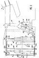
- FIG. 1 roughly schematizes a tank 1 with, in the rear lower part of its chassis 1a, a magazine 2 in which ammunition is stored 3.
- the loading system 10 according to the invention makes it possible to automatically route ammunition 3 from the magazine 2 up to the tube 5 of a barrel 6 supported by the turret 7 of the tank 1.
- the loading system 10 comprises a routing block 11 whose chassis 12 supports a cradle 15 for receiving ammunition 3 which is axially movable relative to the chassis 12, the ammunition 3 being itself axially displaceable relative to the cradle 15.
- the chassis 12 of the routing block 11 is constituted by at least two parallel beams 13 located opposite and connected to each other by transverse elements 14.
- the two opposite faces of the two beams 13 have each a longitudinal groove 16 having generally in cross section the shape of a C.
- the cradle 15 consists of a semi-cylindrical body 15a bordered by two longitudinal flanges 17 which each extend radially outwards.
- the cradle 15 is mounted parallel to the chassis 12 between the two longitudinal members 13 and each of its flanges 17 rotatably supports rollers 18 freely housed inside the grooves 16 associated with the chassis 12 of the routing block 11 to form pathways rolling and guiding of the cradle 15 during its movement relative to the chassis 12.
- a first drive device 20 which comprises, in the example considered here, a first motor member M1, preferably a gear motor, the output shaft of which 21 is integral with a pinion 22 which meshes with a longitudinal rack 23 fixed under the cradle 15 and extending parallel to the flanges 17 thereof.
- a second drive device 25 allows the ammunition 3 which rests on the cradle 15 to move relative thereto.
- This second drive system 25 comprises two endless belts 26 located respectively on either side of the cradle 15 and which each extend substantially over the length thereof.
- the two bands 26 are located slightly above the cradle 15, so that they can come into contact with the ammunition 3.
- each endless strip 26 is wound on two end rollers 27 and 28, with at least one intermediate guide roller 29.
- Each strip 26 thus wound is broken down into an external forward strand b1 and an internal internal return strand b2 to the cradle 15, considering the direction of drive of the strip 2 6 indicated by the arrow D.
- Each strip 26 supports projecting on its external face at least one shoe 26a and one tab 26b which, at the start, are located on the go b aller strand for reasons which will be explained later.
- the rollers 27 are motor rollers driven in rotation from the output shaft 30 of a second motor member M2, preferably a gear motor, situated for example towards a front end or end of the cradle 15 and placed under it.
- a movement transmission device (not shown) allows the output shaft 30 of the second motor M2 to simultaneously drive the two motor rollers 27 in rotation.
- the chassis 12 of the routing block 11 can be moved by means of a tilting device 35, integral with the chassis 1a, which is connected to the chassis 12 by means of two pivoting arms 36 and 37.
- the arm 36 is articulated at one end to the chassis 12 of the routing block 11 and at the other end to the output shaft 38 of a third motor member M3, preferably a gear motor, which controls the pivoting of the arm 36.
- the arm 37 is articulated at its two ends to the chassis 12 of the routing block 11 and to a plate 39 which supports the motor M3, respectively.
- the ammunition 3 is stored vertically inside the magazine 2 which has an outlet opening 2a located opposite the loading system 10.
- Each ammunition 3 is for example mounted in a support case 40.
- Two adjacent cases 40 are hingedly connected to each other so that all of the cases form a closed loop movable along a guide path defined inside the magazine.
- Each case 40 is guided at its upper part by at least one roller 42 which rolls one in an upper guide rail 41a, and at its lower part by at least one ball 43 which rolls in a lower guide rail 41b.
- the set of cases 40 is moved by a drive mechanism comprising a motor member M4, preferably a gear motor, the output shaft of which is coupled to a motion transmission device 44 to drive two horizontal chains, respectively upper 44a and lower 44b which mesh pins side 45 provided on the cases 40.
- a drive mechanism comprising a motor member M4, preferably a gear motor, the output shaft of which is coupled to a motion transmission device 44 to drive two horizontal chains, respectively upper 44a and lower 44b which mesh pins side 45 provided on the cases 40.
- a pivoting vertical arm 50 actuated by a motor member M5, preferably a gear motor, for tilting the munition 3 to 1 in a predetermined position. outside the store 2.
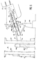
- the loading system 10 is in the rest position or inactive position, the routing block 11 and the cradle 15 being inclined relative to the vertical by an angle of approximately 30 °.
- the motor M3 of the tilting device 35 is actuated so as to bring the routing block 11 closer to the outlet opening of the magazine 2, while tilting it at an angle of about 45 °.
- the motor M5 is actuated to rotate the arm 50 which comes into contact with the ammunition 3 before tilting it so that it is directly received in the cradle 15.
- the second drive device 25 is actuated to advance the two endless bands 26 which run along the cradle 15 until the pads 26a pass over the return strands b2 and come into tight contact with the body 3a of the ammunition 2.
- the angle of inclination reached by the routing block 11 at the end of the second phase of the loading must be precisely defined. Indeed, the ammunition 3 must be in the axis of the tube 5 of the barrel 6 without the turret basket 7a can constitute an obstacle to the progress of the ammunition. Concretely, the angle of inclination that the routing block 11 can take is chosen according to the characteristics specific to the turret basket of the tank in question, and the angle of elevation of the barrel 6 is then adjusted accordingly.
- the cradle 15 is moved axially relative to the support routing block 11 by actuating the first drive device 20.
- the rotation of the motor M1 causes the rotation of the pinion 22 which positively engages the rack 23 secured to the cradle 15.
- the cradle 15 moves axially relative to the routing block 11, which has the effect of bringing the munition 3 closer to the tube 5 of the barrel 6. This thus reaches the position as shown in FIG. 5 where the front end of the munition is in the vicinity of the inlet of the tube 5 of the barrel 6.
- the second drive device 25 is again actuated so as to move the ammunition 3 relative to the cradle 15.
- the endless belts 26 are driven by the motor M2 and the pressure forces exerted by the pads on the body 3a of the ammunition 3 are sufficient to cause the axial displacement of the ammunition 3 relative to the cradle 15 and along it.
- the loading cycle of a munition 3 is finished, and after the projectile has been fired, a new cycle can start again in a manner similar to that described above once the loading system returned to the initial position.
- the invention is not limited to the embodiment described above, and it includes all the technical means equivalent to the means described without departing from the scope of the invention.
- the device for pivoting the ammunition 3 can be replaced by another device, the one which has been described above being particularly well suited in the case of a tank.
- the bands 26 with their pads 26a which firstly maintain the munition when the routing block 11 is moved to align the munition along the axis of the barrel tube, and secondly the movement of the ammunition relative to the cradle, and their legs 26b which then come into contact with the base of the ammunition to push the ammunition, could be replaced by a single device adapted to the space available inside the tank, in particular the turret basket level.
Landscapes
- Engineering & Computer Science (AREA)
- General Engineering & Computer Science (AREA)
- Toys (AREA)
- Replacing, Conveying, And Pick-Finding For Filamentary Materials (AREA)
- Warehouses Or Storage Devices (AREA)
Applications Claiming Priority (2)
| Application Number | Priority Date | Filing Date | Title |
|---|---|---|---|
| FR9112795A FR2682749B1 (fr) | 1991-10-17 | 1991-10-17 | Systeme de chargement automatique d'une munition dans la chambre du tube d'un canon, en particulier du canon d'un char, et char equipe d'un tel dispositif. |
| FR9112795 | 1991-10-17 |
Publications (1)
| Publication Number | Publication Date |
|---|---|
| EP0538138A1 true EP0538138A1 (de) | 1993-04-21 |
Family
ID=9418009
Family Applications (1)
| Application Number | Title | Priority Date | Filing Date |
|---|---|---|---|
| EP92402828A Withdrawn EP0538138A1 (de) | 1991-10-17 | 1992-10-16 | Selbsttätiges Munitionsladesystem für eine Panzerkanone und Panzerung mit solcher Vorrichtung |
Country Status (3)
| Country | Link |
|---|---|
| US (1) | US5335580A (de) |
| EP (1) | EP0538138A1 (de) |
| FR (1) | FR2682749B1 (de) |
Cited By (2)
| Publication number | Priority date | Publication date | Assignee | Title |
|---|---|---|---|---|
| US6460448B1 (en) * | 2000-08-17 | 2002-10-08 | The United States Of America As Represented By The Secretary Of The Army | Automated loader assist for mortars |
| FR3043190A1 (fr) * | 2015-10-29 | 2017-05-05 | Nexter Systems | Refouloir a obus |
Families Citing this family (5)
| Publication number | Priority date | Publication date | Assignee | Title |
|---|---|---|---|---|
| US5773747A (en) * | 1996-05-07 | 1998-06-30 | United Defense, Lp | Two-piece ammunition flick ram |
| FR2778235B1 (fr) * | 1998-04-30 | 2000-06-02 | Giat Ind Sa | Dispositif d'alimentation d'un canon d'artillerie en elements de munition |
| RU2220395C1 (ru) * | 2002-03-29 | 2003-12-27 | Государственное унитарное предприятие "Конструкторское бюро приборостроения" | Орудийная установка |
| US6752063B2 (en) * | 2002-10-31 | 2004-06-22 | United Defense, L.P. | Multiple cell ammunition cradle |
| IT1404036B1 (it) * | 2010-12-17 | 2013-11-08 | Oto Melara Spa | Veicolo armato con struttura migliorata. |
Citations (3)
| Publication number | Priority date | Publication date | Assignee | Title |
|---|---|---|---|---|
| DE3413516A1 (de) * | 1984-04-10 | 1985-10-17 | Industrieanlagen-Betriebsgesellschaft Mbh, 8012 Ottobrunn | Vorrichtung zum halten, fuehren und antreiben von patronen |
| EP0368821A2 (de) * | 1988-10-12 | 1990-05-16 | Aktiebolaget Bofors | In einen Panzer eingebauter Munitionszuführmechanismus |
| EP0450373A1 (de) * | 1990-04-04 | 1991-10-09 | KUKA Wehrtechnik GmbH | Vorrichtung zum Laden von Rohrwaffen, insbesondere von Panzerhaubitzen |
Family Cites Families (6)
| Publication number | Priority date | Publication date | Assignee | Title |
|---|---|---|---|---|
| US1310890A (en) * | 1919-07-22 | Planoqftaph co | ||
| US1602568A (en) * | 1924-07-21 | 1926-10-12 | Thomas A Conlon | Mechanical loader for cannon |
| US2112853A (en) * | 1936-05-04 | 1938-04-05 | Victor F Lucht | Loader for guns |
| DE2818279C2 (de) * | 1978-04-26 | 1983-12-29 | Krauss-Maffei AG, 8000 München | Vorrichtung zum automatischen Fördern und/oder Laden von großkalibriger, patronierter Munition |
| US4823676A (en) * | 1985-10-04 | 1989-04-25 | Fmc Corporation | Autoloader for military vehicle |
| US4898071A (en) * | 1988-09-23 | 1990-02-06 | Fmc Corporation | Inflatable ammunition gripping device |
-
1991
- 1991-10-17 FR FR9112795A patent/FR2682749B1/fr not_active Expired - Fee Related
-
1992
- 1992-10-16 US US07/961,627 patent/US5335580A/en not_active Expired - Fee Related
- 1992-10-16 EP EP92402828A patent/EP0538138A1/de not_active Withdrawn
Patent Citations (3)
| Publication number | Priority date | Publication date | Assignee | Title |
|---|---|---|---|---|
| DE3413516A1 (de) * | 1984-04-10 | 1985-10-17 | Industrieanlagen-Betriebsgesellschaft Mbh, 8012 Ottobrunn | Vorrichtung zum halten, fuehren und antreiben von patronen |
| EP0368821A2 (de) * | 1988-10-12 | 1990-05-16 | Aktiebolaget Bofors | In einen Panzer eingebauter Munitionszuführmechanismus |
| EP0450373A1 (de) * | 1990-04-04 | 1991-10-09 | KUKA Wehrtechnik GmbH | Vorrichtung zum Laden von Rohrwaffen, insbesondere von Panzerhaubitzen |
Cited By (2)
| Publication number | Priority date | Publication date | Assignee | Title |
|---|---|---|---|---|
| US6460448B1 (en) * | 2000-08-17 | 2002-10-08 | The United States Of America As Represented By The Secretary Of The Army | Automated loader assist for mortars |
| FR3043190A1 (fr) * | 2015-10-29 | 2017-05-05 | Nexter Systems | Refouloir a obus |
Also Published As
| Publication number | Publication date |
|---|---|
| FR2682749B1 (fr) | 1993-12-10 |
| FR2682749A1 (fr) | 1993-04-23 |
| US5335580A (en) | 1994-08-09 |
Similar Documents
| Publication | Publication Date | Title |
|---|---|---|
| EP0694750B1 (de) | Munitionszufuhrsystem für Waffen von kleinem oder mittlerem Kaliber | |
| EP0592344B1 (de) | Abschussvorrichtung für Tontauben | |
| CH427548A (fr) | Machine à rectifier les briques | |
| EP0783094B1 (de) | Vorrichtung zum Überführen von Treibladungen aus einem Magazin in eine Ladevorrichtung | |
| EP2957487B1 (de) | Instandsetzungsvorrichtung für eine fahrzeug-laufkette, vorrichtung und verfahren zum wechseln der ketten-laufflächen mithilfe dieser instandsetzungsvorrichtung | |
| FR2610396A1 (fr) | Systeme de chargement pour conteneurs contenant des munitions a cartouche | |
| EP0538138A1 (de) | Selbsttätiges Munitionsladesystem für eine Panzerkanone und Panzerung mit solcher Vorrichtung | |
| FR2496249A1 (fr) | Dispositif d'alimentation automatique pour armes a feu, notamment pour un canon monte dans une tourelle de char plate | |
| EP0538137B1 (de) | Munitionsmagazin, insbesondere für Kampfpanzer | |
| EP0953818B1 (de) | Ladevorrichtung für Munitionselemente an einem Geschütz | |
| EP0041017A1 (de) | Transportvorrichtung für zylindrische Gegenstände, wie z.B. Munition | |
| EP0140782B1 (de) | Vorrichtung zum Zuführen und Laden von Munition in Feuerwaffen in beliebigen Elevations- und Azimutlagen | |
| EP0706022A1 (de) | Vorrichtung zum Zuführen von Geschossmunition für eine klein- oder grosskalibrige Feuerwaffe an einem Turm eines Panzerfahrzeugs | |
| EP0125176B1 (de) | Militärische Einrichtung mit Panzerturm, der mit einer aussen liegenden Hauptwaffe versehen ist | |
| FR2524136A1 (fr) | Mecanisme pour alimenter en munitions une arme a double tube | |
| FR2696538A1 (fr) | Perfectionnement lié aux appareils pour le lancement de plateaux ou cibles mobiles. | |
| FR2647888A1 (fr) | Unite de tir avec mortier entierement automatisee | |
| FR2465660A1 (fr) | Installation de stockage et de reprise automatique de betteraves, tubercules et autres produits en vrac | |
| FR3044753A1 (fr) | Dispositif de manutention d'obus pour piece d'artillerie | |
| FR2925149A1 (fr) | Magasin d'alimentation semi-automatique en munitions d'une arme | |
| WO1996036845A1 (fr) | Arme a feu automatique multitubes de petit ou moyen calibre du type gatling, notamment destinee au tir de munitions telescopees | |
| EP0571266B1 (de) | Einrichtung zum Laden von Munition in einem schwenkbaren Patronenlager | |
| FR2502767A1 (fr) | Dispositif de chargement pour arme a canon mobile incorporee a un vehicule blinde | |
| FR2680869A1 (fr) | Arbalete avec moyen perfectionne de guidage du carreau et moyen de chargement automatique en carreaux. | |
| CH383879A (fr) | Appareil de manutention de bouteilles |
Legal Events
| Date | Code | Title | Description |
|---|---|---|---|
| PUAI | Public reference made under article 153(3) epc to a published international application that has entered the european phase |
Free format text: ORIGINAL CODE: 0009012 |
|
| AK | Designated contracting states |
Kind code of ref document: A1 Designated state(s): DE GB |
|
| 17P | Request for examination filed |
Effective date: 19930510 |
|
| 17Q | First examination report despatched |
Effective date: 19941025 |
|
| STAA | Information on the status of an ep patent application or granted ep patent |
Free format text: STATUS: THE APPLICATION HAS BEEN WITHDRAWN |
|
| 18W | Application withdrawn |
Withdrawal date: 19961012 |