EP0538331B1 - Strahlmittelschleuderrad - Google Patents
Strahlmittelschleuderrad Download PDFInfo
- Publication number
- EP0538331B1 EP0538331B1 EP91912764A EP91912764A EP0538331B1 EP 0538331 B1 EP0538331 B1 EP 0538331B1 EP 91912764 A EP91912764 A EP 91912764A EP 91912764 A EP91912764 A EP 91912764A EP 0538331 B1 EP0538331 B1 EP 0538331B1
- Authority
- EP
- European Patent Office
- Prior art keywords
- throwing
- blade
- side plate
- assembly
- wheel
- Prior art date
- Legal status (The legal status is an assumption and is not a legal conclusion. Google has not performed a legal analysis and makes no representation as to the accuracy of the status listed.)
- Expired - Lifetime
Links
- 238000000429 assembly Methods 0.000 title description 4
- 230000000712 assembly Effects 0.000 title description 4
- 125000006850 spacer group Chemical group 0.000 claims abstract description 7
- 230000015572 biosynthetic process Effects 0.000 claims description 26
- 238000005755 formation reaction Methods 0.000 claims description 26
- 238000010276 construction Methods 0.000 claims description 9
- 230000004888 barrier function Effects 0.000 claims description 8
- 230000014759 maintenance of location Effects 0.000 claims description 7
- 230000000717 retained effect Effects 0.000 claims description 3
- 230000000295 complement effect Effects 0.000 claims 2
- 230000001419 dependent effect Effects 0.000 claims 2
- 238000009825 accumulation Methods 0.000 abstract description 4
- 230000001815 facial effect Effects 0.000 description 3
- 238000007789 sealing Methods 0.000 description 3
- 239000007787 solid Substances 0.000 description 3
- 230000037431 insertion Effects 0.000 description 2
- 238000003780 insertion Methods 0.000 description 2
- 230000002441 reversible effect Effects 0.000 description 2
- 238000010079 rubber tapping Methods 0.000 description 2
- 230000002411 adverse Effects 0.000 description 1
- 238000005422 blasting Methods 0.000 description 1
- 238000011109 contamination Methods 0.000 description 1
- 238000000151 deposition Methods 0.000 description 1
- 230000009977 dual effect Effects 0.000 description 1
- 230000000694 effects Effects 0.000 description 1
- 238000002347 injection Methods 0.000 description 1
- 239000007924 injection Substances 0.000 description 1
- 239000000463 material Substances 0.000 description 1
- 230000000116 mitigating effect Effects 0.000 description 1
- 238000003466 welding Methods 0.000 description 1
Images



Classifications
-
- B—PERFORMING OPERATIONS; TRANSPORTING
- B24—GRINDING; POLISHING
- B24C—ABRASIVE OR RELATED BLASTING WITH PARTICULATE MATERIAL
- B24C5/00—Devices or accessories for generating abrasive blasts
- B24C5/06—Impeller wheels; Rotor blades therefor
- B24C5/062—Rotor blades or vanes; Locking means therefor
Definitions
- This invention relates to centrifugal abrasive throwing wheel assemblies such as are used in shot blasting machinery.
- One form of throwing wheel assembly comprises, inter alia , a throwing wheel and a set of throwing blades.
- the throwing wheel comprises a pair of annular side plates conjoined in parallel relationship by spacers.
- the inside face of each side plate is formed with a number of angularly-spaced slots extending between the inner and outer diameters of the side plate, the numbers of slots being equal to the number of throwing blades in the set of throwing blades.
- the slots in the side plates are in register and serve to mount the throwing blades within the throwing wheel.
- a throwing blade has at least one throwing face and its lateral edges are usually of greater depth, viewing the throwing blade in transverse cross-section, but not necessarily so.
- the opposed lateral edges, so-called rails if of greater depth than the throwing face or faces, of a throwing blade engage and are located in a pair of registering slots to mount the throwing blade in the throwing wheel and various securing arrangements, well known to those skilled in the art, are employed releasably to retain the throwing blades within the throwing wheel for operational purposes.
- the throwing blades may be inserted into their locating slots or grooves either from the inner diameter or the outer diameter of the throwing wheel.
- the side plates are internally slotted to accept and locate complementarily-shaped solid lateral rails or edges of throwing blades, i.e. a female (side plate slots) and a male (solid throwing blade lateral rails or edges) connection and location, i.e. there is three-sided inter-facial contact between the lateral rails or edges and walls of the slots.
- the invention is concerned with a throwing wheel assembly in which the throwing blades are fitted into and withdrawn from the throwing wheel through the central opening of the throwing wheel, the blades being retained in position within the wheel by abutment of co-operating formations on the throwing blades and the side plates of the throwing wheel. Inward movement of the blades in the throwing wheel assembly is prevented by the presence of the customary removable control cage and vane-type impeller with combined or separate centering plate traversing the central openings of the side plates.
- the side plates of the throwing wheel are, as is customary, radially slotted to receive and locate the lateral rails of the throwing blades, each slot at its inner end, i.e. adjacent to the central opening, being deeper than the remainder of the slot to define a ledge against which abuts a nose provided on each lateral rail of the throwing blade.
- this Patent there is disclosed lateral radial location of the throwing blades between the side plates.
- both faces of each throwing blade are identical so that the throwing wheel assembly is operationally reversible.
- each throwing blade has mounted in each lateral rail adjacent its inner end, when considering the throwing blade mounted in its throwing wheel, a synthetic polymeric or elastomeric strip which stands proud of the lateral rail and which lies within a dovetail-shaped groove disposed perpendicular to planes containing the throwing faces of the throwing blades.
- These strips serve both to provide a barrier to flow of fine abrasive and/or contaminations up the lateral rails of the throwing blades with consequent wear thereon and on the walls of the slots and to frictionally hold the throwing blades in position between the side plates of the throwing wheel until the centering plate, with or without the combined vane-type impellor and the control cage are located within the central opening of the throwing wheel.
- worn throwing blades are removable for replacement purposes by firstly removing the control cage and the vane-type impeller with combined or separate centering plate and then tapping the throwing blades inwardly for removal through the central opening in one of the side plates.
- an abrasive throwing wheel assembly comprising a throwing wheel constituted by a pair of parallel annular side plates joined by angularly-spaced spacers, a plurality of throwing blades located between the side plates, and cooperating securing formations at or adjacent the inner diameter of the side plates and the radially inner ends of each throwing blade lateral edges or rails which resist or prevent radially outward movement of the throwing blade relative to the side plates, the abrasive throwing wheel assembly being characterised in that each side plate has a plurality of angularly-spaced, radially-extending throwing blade locating projections, in that each throwing blade is provided with a longitudinal groove extending inwardly from its tip but terminating short of its inner end (41B), and in that the projections and grooves are configured to provide axial spacing therebetween thereby defining a radial clearance passage therebetween.
- a throwing blade as claimed in claim 25, and for use and assembly therewith a side plate as claimed in claim 33.
- the throwing blades in accordance with the present invention can and may be employed with conventional and known throwing wheels, i.e. those where the side plates have single simple slots for receiving and locating throwing blade lateral rails or edges.
- the blade grooves and the side wall blade locating projections may be of such a configuration that there is angularly spaced facial and/or line (point) contact between the lateral rails or edges of the throwing blade and the blade locating projections of the side plates thereby easing throwing blade removal from between the side plates.
- the blade locating projections are omitted, i.e. the radial slots are simple single slots, then there are angularly spaced areas of facial contact between a side plate and the adjacent lateral rail or edge of a throwing blade.
- the throwing blade incorporates the synthetic polymeric or elastomeric location and barrier strips.
- each strip is moulded, preferably injection moulded, into its dovetail-shaped groove in the throwing blade lateral rail or edge and is in the form of a wiper blade which will give the required frictional holding and abrasive barrier characteristics.
- the groove may be other than dovetail-shaped provided it can retain the flexible wiper blade in position on the throwing blade. It is likely that the flexible wiper blade will only stand proud laterally of the throwing blade lateral rail or edge.
- a synthetic polymeric or elastomeric insert may be located in the bottom of one, or each, groove of a throwing blade, preferably spaced from the blade securing formation for blade retention purposes.
- the throwing blade 20 (see Figs. 1 to 4 and Fig. 10) has an inner body 21 with integral lateral rails 22, the inner body 21 having two identical throwing faces 23 which renders the throwing blade 20 suitable for use in a reversible (bi-directional) abrasive throwing wheel assembly.
- each lateral rail 22 At the inner end of each lateral rail 22 is a laterally-projecting protuberance 24 tapered to define a blunt nose 25.
- the laterally-projecting protuberance 24 has formed therein a dovetail-shaped slot 26 in which is force fitted a polymeric or elastomeric sealing strip 27 which stands proud of the protuberance 24 both laterally and at its ends.
- the sealing strips 27 assists in reducing abrasive wear on the side plates of a throwing wheel in which the throwing blade 20 is mounted and in the location and retention of the throwing blade 20 between the side plates during throwing wheel assembly.
- each lateral rail 22 is formed with a V-groove 28 open to the side face of the throwing blade 20 and extending from the tip of the latter to the blunt nose 25 of protuberance 24.
- These grooves 28 define female configurations which are used to locate and retain the throwing blade 20 in position between side plates of a throwing wheel.
- each lateral rail 22 is greater than usual. For example, 10 millimetres as opposed to the usual 7 millimetres.
- slots 26 and strips 27 may be omitted if desired.
- this comprises a pair of annular parallel side plates 29 joined together by spacers 29A, there being, between angularly-adjacent spacers 29A, throwing blade locating slots.
- Each side plate 29 (see Figs. 5 and 6 especially) is, as aforesaid, of annular construction and is formed with a series of angularly-spaced, radial, throwing blade locating slots generally indicated at 30.
- each of these slots 30 is divided into two sub-slots 30A, 30B for part of the radial length of the slot 30 by a centrally disposed projection 30C extending from the outer circumference of the side plate 29 to a recess 31 at the inner end of the slot 29, which recess 31 defines a ledge 32 against which the nose 25 of a throwing blade rail 22 will abut.
- the sub-slots 30A and 30B are of rectangular cross-section (see Fig. 7) as is the separating projection 30C.
- the slot or groove 30 in the side plate 29 is a conventional simple slot as is currently usual in the side plates of throwing wheels.
- the configuration of the lateral rail 22 of the throwing blade 20 is shown to conform with that of Fig. 7 but it may equally conform to that of Fig. 8.
- a comparison of the throwing blades of Figs. 7 and 8 shows that the side plate adjacent face of the lateral rail 22 of the latter presents a lesser area of rail contact to the side plate 29 than the former. This is due to the different contact configurations between the throwing blade rails 22 and the projections 30C of the grooves 30 of the side plates 29.
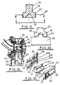
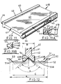
- Figs. 11 to 14 show a preferred throwing blade construction and throwing blade and side plate connection according to this invention.
- the throwing blade 40 has a body 41 defining identical throwing faces 42 bounded by two lateral rails 43 of greater depth than the body 41.
- Each lateral rail 43 is formed with a V-groove 44 extending from the tip 41A of the blade 40 for a major part of its length to a location 45 where the rail 43 is left full.
- the groove 44 therefore, is arrested at 45 to define a securing formation.
- a synthetic polymeric or elastomeric insert 46 is secured in any convenient manner within each groove 44 towards the bottom thereof, i.e. it does not fill the groove 44, and is spaced as indicated at 47 from the blade securing formation 45.
- inserts 46 serve primarily to assist in blade retention between the side plates of a throwing wheel during assembly and act secondarily as abrasive flow barriers during use of the throwing wheel.
- the inserts 46 may be omitted or alternatively may be provided on one side only of the throwing blade 40.
- Throwing blades 40 in accordance with Fig. 11 may be produced by forming, in any convenient manner, a length of blade strip with the grooves 44 extending the full length of the strip, cutting the strip into the desired throwing blade lengths and thereafter, at one end, welding, tapping or otherwise securing within the grooves 44 inserts to provide the blade securing formation 45, or even simply depositing weld material in the grooves 44 at said ends to provide the necessary abutment surfaces.
- the abutment surfaces 45 can be provided in the grooves 44 in any convenient fashion.
- an abutment surface 45 can be provided in only one groove 44 of a throwing blade 40 if desired.
- Fig. 12 in which 50 indicates a throwing wheel side plate with a preferred form of slots 51 (only one shown).
- the slot 51 viewed from the circumference of the side plate 50 has a flat base 52 bounded by two diverging inclined side walls 53.
- a locating projection 54 is provided centrally of the slot 51 and is of triangular configuration with a narrow flat top in cross-section.
- the angle a defined by the side walls of the projection 54 is equal to 90° while the angle b subtended by the side walls of the groove 44 is equal to 100°.
- the blade rail 43 makes only line or point contact with the projection 54 at two angularly spaced locations, the remaining adjacent surfaces of the blade rail 43 and the projection 54 being in spatial relationship.
- the angular width of the slot 51 at its widest part A is three times the thickness B of the throwing blade rail 43 and at its narrowest part C is two and one half times thickness B.
- FIG. 12 Another important advantage of the throwing blade and side plate slot configuration of Fig. 12 is reduction in wear on the side plate 50, especially at its outer circumference or rim, thus increasing the working life of the throwing wheel.
- Figs. 13 and 14 show a throwing wheel 60 (see Fig. 14) constituted by two parallel side plates 50, 50A joined, in conventional manner, by spacers 61.
- the side plates 50, 50A are formed with registering slots 51 as described with reference to Fig. 12 in which a fitted throwing blade 40 as described with reference to Fig. 11.
- the central projection 54 may be of continuous length as exemplified at location X or it may be interrupted or discontinuous as indicated at location Y.
- a throwing blade 40A of a length sufficient to pass through the central hole 55 of one of the side plates 50 can, as indicated by arrows, be slid into the slots 51 until the securing locations 45 abut the inner ends of the projections 54 which are received in the grooves 44.
- the throwing blades As a result of the present invention and by suitably dimensioning the blade locating projections it is possible for a given size (external diameter) of throwing wheel to employ throwing blades of different lengths, the throwing blades, as aforesaid, being insertable between the side plates either through the centre of the side plates or from the outside rim of the side plates depending on throwing blade length, the sub-slots being used for such outside insertion.
- the throwing blades of a given throwing wheel will usually be the same length.
- Fig. 15 it can be seen that the throwing blades 20 (40) as hereinbefore described in the throwing wheel assembly are retained in position between the side plates 29 (50) as hereinbefore described after central or external insertion by the control cage 33 and the integral centering plate 34 and vane-type impellor 35 which is removably secured to a wheel hub 36 bolted to one of the side plates 29 and secured to a motor shaft 37.
- Fig. 16 shows a possible further construction of throwing wheel in which the side plates 29 are not formed internally with throwing blade locating slots 30 but only with inwardly projecting ribs 38 equivalent to projections 30C (54), the throwing blades 20 (40) being grooved in their lateral rails or edges 22 (43) as described, thus providing the reduced inter-facial contact, male/female connection between side plate/throwing blade which is the characteristic feature of the present invention.
- the ribs 38 may be integral with or separate and attached to the side plates.
- an abrasive throwing wheel assembly comprising, inter alia, a throwing wheel having annular side plates with registering inwardly-directed projections provided thereon for mounting throwing blades formed with a lateral rail or edge of grooved or recessed configuration within which a projection can be located.
- This aspect of the present invention also extends to a side plate for a throwing wheel having integral or separate but attached projecting ribs only (no slots or grooves) on its throwing blade mounting face.
Landscapes
- Engineering & Computer Science (AREA)
- Mechanical Engineering (AREA)
- Polishing Bodies And Polishing Tools (AREA)
- Tires In General (AREA)
- Turbine Rotor Nozzle Sealing (AREA)
- Surgical Instruments (AREA)
- Stereoscopic And Panoramic Photography (AREA)
- Testing, Inspecting, Measuring Of Stereoscopic Televisions And Televisions (AREA)
Claims (41)
- Strahlmittelwurfrad-Baugruppe, die folgendes umfaßt: ein Wurfrad (60), das ein Paar parallele ringförmige Seitenscheiben (29, 50, 50A) aufweist, die durch im winkligen Abstand zueinander angeordnete Distanzstücke (29A, 61) miteinander verbunden sind, eine Mehrzahl von zwischen den Seitenscheiben (29, 50, 50A) angeordneten Wurfblättern (20, 40, 40A, 40B) und zusammenwirkende Befestigungsgebilde (24, 25; 45 und 31, 32; und 54) an oder neben dem inneren Durchmesser der Seitenscheiben (29, 50, 50A) und den radial inneren Enden der Seitenkanten oder -schienen (22, 43) jedes Wurfblatts, die einer radial nach außen gerichteten Bewegung des Wurfblatts (20, 40, 40A, 40B) im Verhältnis zu den Seitenscheiben (29, 50, 50A) widerstehen oder sie verhindern, wobei die Strahlmittelwurfrad-Baugruppe dadurch gekennzeichnet ist, daß jede Seitenscheibe (29, 50, 50A) eine Mehrzahl von im winkligen Abstand zueinander angeordneten, sich radial erstreckenden Wurfblattpaßvorsprüngen (30C, 54) hat, daß jedes Wurfblatt (20, 40, 40A, 40B) mit einer sich von seiner Spitze (41A) nach innen erstreckenden, aber kurz vor seinem inneren Ende (41B) endenden Längsrille (28, 44) versehen ist, und daß die Vorsprünge (30C, 54) und Rillen (28, 44) ausgebildet sind, um einen axialen Abstand zwischen sich vorzusehen, wodurch zwischen ihnen eine radiale Aussparung definiert wird.
- Baugruppe nach Anspruch 1, dadurch gekennzeichnet, daß der Körper (20, 41) des Blatts (20, 40, 40A, 40B) zwischen seinen Seitenschienen oder -kanten (22, 43) entgegengesetzte identische Wurfflächen (23, 42) definiert.
- Baugruppe nach Anspruch 1 oder 2, dadurch gekennzeichnet, daß jede Blattrille (28, 44) oder eine davon in einem Blattbefestigungsgebilde (24, 25; 45) endet, das zum Zusammenwirken mit einem ergänzenden Gebilde (31, 32; 54) an einer zugeordneten Seitenscheibe (29, 50, 50A) angepaßt ist, um einer radial nach außen gerichteten Bewegung des Wurfblattes (20, 40, 40A, 40B) im Verhältnis zum Wurfrad (60) zu widerstehen.
- Baugruppe nach Anspruch 3, dadurch gekennzeichnet, daß das oder jedes Befestigungsgebilde (45) innerhalb der oder jeder Seitenschiene oder -kante (43) liegt.
- Baugruppe nach Anspruch 3, dadurch gekennzeichnet, daß sich das oder jedes Befestigungsgebilde (24, 25) seitlich über die oder jede Seitenschiene oder -kante (22) hinaus erstreckt.
- Baugruppe nach einem der Ansprüche 3 bis 5, dadurch gekennzeichnet, daß jedes Befestigungsgebilde (24, 25; 45) an, neben oder mit Abstand zu dem spitzenentfernten Ende (41B) des Blatts (20, 40, 40A, 40B) angeordnet ist.
- Baugruppe nach einem der Ansprüche 3, 5 oder 6, wenn in Abhängigkeit von Anspruch 3 oder 5, dadurch gekennzeichnet, daß das oder jedes Befestigungsgebilde (24, 25) einen polymeren oder elastomeren Kunststoffstreifen (27) aufnimmt, der seitlich aus dem oder jedem Befestigungsgebilde (24, 25) herausragt, um eine Blatthaltekonfiguration und eine Strahlmittelflußsperre vorzusehen.
- Baugruppe nach einem der Ansprüche 3, 4 oder 7, wenn in Abhängigkeit von Anspruch 3 oder 4, dadurch gekennzeichnet, daß im Boden der oder jeder Blattrille (44) ein polymerer oder elastomerer Kunststoffeinsatz (46) mit Abstand von dem oder jedem Befestigungsgebilde (45) angeordnet ist, um eine Blatthaltekonfiguration und eine Strahlmittelflußsperre vorzusehen.
- Baugruppe nach einem der Ansprüche 1 bis 8, dadurch gekennzeichnet, daß die Rille (28, 44) in der oder jeder Blattseitenschiene oder -kante (22, 43) eine V- oder U-förmige oder rechteckige Konfiguration hat.
- Baugruppe nach Anspruch 1 oder 2, dadurch gekennzeichnet, daß jeder radial gelegene Vorsprung in einem Schlitz (30, 51) angeordnet ist, der sich vom äußeren Durchmesser seiner Seitenscheibe (29, 50, 50A) radial nach innen erstreckt.
- Baugruppe nach Anspruch 10, dadurch gekennzeichnet, daß die im winkligen Abstand zueinander angeordneten radialen Schlitze (30, 51) jeder Radseitenscheibe (29, 50, 50A) jeweils zumindest auf einem Teil ihrer radialen Länge durch den betreffenden Wurfblattpaßvorsprung (30C, 54) geteilt oder unterteilt sind, um für den genannten radialen Längenabschnitt ein Paar nebeneinanderliegender Nebenschlitze (30A, 30B; 51A) zu definieren.
- Baugruppe nach Anspruch 11, dadurch gekennzeichnet, daß sich der Paßvorsprung (30C, 54) vom äußeren Durchmesser des Rads (60) radial nach innen erstreckt und in einem vorbestimmten Abstand vom inneren Durchmesser des Rads (60) endet.
- Baugruppe nach Anspruch 11 oder 12, dadurch gekennzeichnet, daß jeder Paßvorsprung (30C, 54) oder einige davon nicht durchgehend oder unterbrochen ausgestaltet ist oder sind.
- Baugruppe nach einem der Ansprüche 10 bis 13, dadurch gekennzeichnet, daß jeder Seitenscheibenschlitz (30, 51), wenn die Seitenscheibe (29, 50, 50A) von ihrem äußeren Rand betrachtet wird, eine Konfiguration mit flachem Boden und divergierenden Seitenwänden hat.
- Baugruppe nach einem der Ansprüche 10 bis 13, dadurch gekennzeichnet, daß jeder Seitenscheibenschlitz (30, 51), wenn die Seitenscheibe (29, 50, 50A) von ihrem äußeren Rand betrachtet wird, eine Konfiguration mit flachem Boden und rechtwinkligen Seitenwänden hat.
- Baugruppe nach einem der Ansprüche 10 bis 15, dadurch gekennzeichnet, daß die Winkel- oder Umfangslänge jedes Seitenscheibenschlitzes (30, 51) mindestens zweimal so groß ist wie die Dicke einer Blattseitenschiene oder -kante (22, 43).
- Baugruppe nach einem der Ansprüche 1 bis 16, dadurch gekennzeichnet, daß jeder Blattpaßvorsprung (30C, 54) oder einige davon, wenn die Seitenscheibe (29, 50, 50A) von ihrem äußeren Rand betrachtet wird, eine dreieckige oder V-förmige Konfiguration oder einen dreieckigen oder V-förmigen Querschnitt mit oder ohne eine(r) abgeflachte(n) Oberseite oder eine rechteckige Konfiguration oder einen rechteckigen Querschnitt mit oder ohne abgeschrägte(n) obere(n) Ecken aufweist oder aufweisen.
- Baugruppe nach Anspruch 17, dadurch gekennzeichnet, daß jede Blattrille (28, 44) eine V-förmige oder dreieckige Konfiguration hat und jeder Seitenscheibenpaßvorsprung (30C, 54) eine V-förmige oder dreieckige Konfiguration oder einen V-förmigen oder dreieckigen Querschnitt hat, wobei der den Seiten der V-förmig konfigurierten Rille (28, 44) gegenüberliegende Winkel größer ist als der von den Seiten der V-förmig konfigurierten Paßvorsprünge (30C, 54) definierte Winkel.
- Baugruppe nach Anspruch 18, bei der die betreffenden Winkel 100° und 90° betragen.
- Baugruppe nach einem der Ansprüche 1 bis 19, dadurch gekennzeichnet, daß jede Seitenscheibe (29, 50, 50A) zwischen vier und acht mit gleichwinkligen Abständen zueinander angeordnete radiale Schlitze (30, 51) hat.
- Baugruppe nach einem der Ansprüche 1 bis 20, dadurch gekennzeichnet, daß Seitenscheiben (29, 50, 50A) des Rads (60) eine größere Dicke oder Tiefe als die andere Seitenscheibe haben, wobei die dickere Seitenscheibe für die Befestigung an einer Nabe, an der ein Antriebsmotor angeschlossen werden kann, oder zur direkten Befestigung an einem Antriebsmotor angepaßt ist.
- Baugruppe nach einem der Ansprüche 1 bis 21, dadurch gekennzeichnet, daß die Blätter (20, 40, 40A, 40B) zwischen den Seitenscheiben (29, 50, 50A) von einem Steuerkäfig (33), der ein rotierbares Flügelrad (35) umgibt und in den mittleren Löchern der Seitenscheiben (29, 50, 50A) sitzt, in Position gehalten werden.
- Baugruppe nach Anspruch 22, bei der das rotierbare Flügelrad (35) eine an einer Antriebsnabe (36) oder einem Motor befestigbare, integrierte Zentrierscheibe (34) zum Drehen der Wurfrad-Baugruppe und des Flügelrads (35) aufweist.
- Baugruppe nach Anspruch 22 oder 23, die einen mit dem Steuerkäfig (33) verbundenen Strahlmittelausfluß umfaßt.
- Wurfblatt zur Verwendung in einer Strahlmittelwurfrad-Baugruppe nach Anspruch 1, dadurch gekennzeichnet, daß jede Seitenschiene oder -kante (22, 43) des Wurfblatts (20, 40, 40A, 40B) zwischen seiner Vorder- und Rückseite (23, 42) vorgesehen oder geformt ist, wobei sich eine Längsrille (28, 44) von der Spitze (41) des Blatts (20, 40, 40A, 40B) für Blattpaßzwecke nach innen erstreckt und kurz vor dem anderen oder inneren Ende (41B) des Blatts (20, 40, 40A, 40B) endet.
- Wurfblatt nach Anspruch 25, dadurch gekennzeichnet, daß jede Rille (28, 44) oder einige davon in einem Blattbefestigungsgebilde (24, 25; 45) endet oder enden, das zum Zusammenwirken mit einem ergänzenden Gebilde (31, 32; 54) auf einer betreffenden Seitenscheibe (29, 50, 50A) des Wurfrads (60) angepaßt ist, um einer radial nach außen gerichteten Bewegung des Wurfblattes (20, 40, 40A, 40B) im Verhältnis zum Wurfrad (60) zu widerstehen.
- Wurfblatt nach Anspruch 26, dadurch gekennzeichnet, daß das oder jedes Befestigungsgebilde (45) innerhalb der oder jeder Seitenschiene oder -kante (22, 43) liegt.
- Wurfblatt nach Anspruch 26, dadurch gekennzeichnet, daß sich das oder jedes Befestigungsgebilde (24, 25) seitlich über die oder jede Seitenschiene oder -kante (22, 23) hinaus erstreckt.
- Wurfblatt nach einem der Ansprüche 26 bis 28, dadurch gekennzeichnet, daß jedes Befestigungsgebilde (24, 25; 45) an, neben oder mit Abstand zu dem spitzenentfernten Ende (41A) des Blatts (20, 40, 40A, 40B) angeordnet ist.
- Wurfblatt nach Anspruch 26 oder 28, dadurch gekennzeichnet, daß das oder jedes Befestigungsgebilde (24, 25) einen polymeren oder elastomeren Kunststoffstreifen (27) aufnimmt, der seitlich aus dem oder jedem Befestigungsgebilde (24, 25) herausragt, um eine Blatthaltekonfiguration und eine Strahlmittelflußsperre vorzusehen.
- Wurfblatt nach Anspruch 26 oder 27, dadurch gekennzeichnet, daß im Boden der oder jeder Blattrille (44) ein polymerer oder elastomerer Kunststoffeinsatz (46) mit Abstand von dem oder jedem Befestigungsgebilde (45) angeordnet ist, um eine Blatthaltekonfiguration und eine Strahlmittelflußsperre vorzusehen.
- Wurfblatt nach einem der Ansprüche 25 bis 31, dadurch gekennzeichnet, daß der Körper (20, 41) des Blatts (20, 40, 40A, 40B) zwischen seinen Seitenschienen oder -kanten (22, 43) entgegengesetzte identische Wurfflächen (23, 42) definiert.
- Seitenscheibe für eine Strahlmittelwurfrad-Baugruppe nach Anspruch 1, wobei die Seitenscheibe (29, 50, 50A) einen ringförmigen Aufbau mit einer Mehrzahl von im winkligen Abstand zueinander angeordneten, radialen Schlitzen (30, 51), die sich zwischen dem inneren und äußeren Durchmesser der Seitenscheibe (29, 50, 50A) erstrecken, hat, dadurch gekennzeichnet, daß jeder Schlitz (30, 51) zumindest auf einem Teil seiner radialen Länge durch einen Wurfblattpaßvorsprung (30C, 54) geteilt oder unterteilt ist, um für den genannten radialen Längenabschnitt ein Paar nebeneinanderliegender Nebenschlitze (30A, 30B; 51A) zu definieren, und die Winkel- oder Umfangslänge jedes Schlitzes (30, 51) größer ist als die Dicke von Rück- zu Vorderseite eines Wurfblatts (20, 40, 40A, 40B).
- Seitenscheibe nach Anspruch 33, dadurch gekennzeichnet, daß sich der Paßvorsprung (30C, 54) vom äußeren Durchmesser radial nach innen erstreckt und in einem vorbestimmten Abstand vom inneren Durchmesser endet.
- Seitenscheibe nach Anspruch 33, dadurch gekennzeichnet, daß sich der Paßvorsprung (30C, 54) vom äußeren Durchmesser radial zum inneren Durchmesser der Seitenscheibe (29, 50, 50A) erstreckt.
- Seitenscheibe nach einem der Ansprüche 33 bis 35, dadurch gekennzeichnet, daß jeder Paßvorsprung (30C, 54) oder einige davon nicht durchgehend oder unterbrochen ausgestaltet ist oder sind.
- Seitenscheibe nach einem der Ansprüche 33 bis 36, dadurch gekennzeichnet, daß jeder Schlitz (30, 51), wenn die Seitenscheibe von ihrem äußeren Rand betrachtet wird, eine Konfiguration mit flachem Boden und divergierenden Seitenwänden hat.
- Seitenscheibe nach einem der Ansprüche 33 bis 36, dadurch gekennzeichnet, daß jeder Schlitz (30, 51), wenn die Seitenscheibe von einem äußeren Rand betrachtet wird, eine Konfiguration mit flachem Boden und rechtwinkligen Seitenwänden hat.
- Seitenscheibe nach einem der Ansprüche 33 bis 38, dadurch gekennzeichnet, daß jeder Paßvorsprung (30C, 54) oder einige davon, wenn die Seitenscheibe von ihrem äußeren Rand betrachtet wird, eine dreieckige Konfiguration oder einen dreieckigen Querschnitt mit oder ohne eine(r) abgeflachte(n) Oberseite oder eine rechteckige Konfiguration oder einen rechteckigen Querschnitt mit oder ohne abgeschrägte(n) obere(n) Ecken aufweist oder aufweisen.
- Seitenscheibe nach einem der Ansprüche 33 bis 39, dadurch gekennzeichnet, daß die Winkel- oder Umfangslänge jedes Schlitzes (29, 50, 50A) mindestens zweimal so groß ist wie die Dicke einer Blattseitenschiene oder -kante (22, 43).
- Seitenscheibe nach einem der Ansprüche 33 bis 40, dadurch gekennzeichnet, daß sie zwischen vier und acht mit gleichwinkligen Abständen zueinander angeordnete radiale Schlitze (29, 50, 50A) hat.
Applications Claiming Priority (3)
| Application Number | Priority Date | Filing Date | Title |
|---|---|---|---|
| GB9014994 | 1990-07-06 | ||
| GB909014994A GB9014994D0 (en) | 1990-07-06 | 1990-07-06 | Abrasive throwing wheel assemblies |
| PCT/GB1991/001075 WO1992000835A1 (en) | 1990-07-06 | 1991-07-02 | Abrasive throwing wheel assemblies |
Publications (2)
| Publication Number | Publication Date |
|---|---|
| EP0538331A1 EP0538331A1 (de) | 1993-04-28 |
| EP0538331B1 true EP0538331B1 (de) | 1995-09-20 |
Family
ID=10678763
Family Applications (1)
| Application Number | Title | Priority Date | Filing Date |
|---|---|---|---|
| EP91912764A Expired - Lifetime EP0538331B1 (de) | 1990-07-06 | 1991-07-02 | Strahlmittelschleuderrad |
Country Status (9)
| Country | Link |
|---|---|
| US (2) | US5577953A (de) |
| EP (1) | EP0538331B1 (de) |
| JP (1) | JP3071822B2 (de) |
| AT (1) | ATE128059T1 (de) |
| AU (1) | AU8207591A (de) |
| CA (1) | CA2086760C (de) |
| DE (1) | DE69113270T2 (de) |
| GB (2) | GB9014994D0 (de) |
| WO (1) | WO1992000835A1 (de) |
Families Citing this family (15)
| Publication number | Priority date | Publication date | Assignee | Title |
|---|---|---|---|---|
| US5888125A (en) * | 1997-11-06 | 1999-03-30 | B&U Corporation | Abrasive blast wheel with improved serviceability |
| US6949014B2 (en) * | 2003-11-17 | 2005-09-27 | Wheelabrator Group, Inc. | Control cage for abrasive blast wheel |
| ES2308512T3 (es) * | 2004-06-24 | 2008-12-01 | Jost Wadephul | Rodete para alimentar un medio de chorreado a una rueda centrifuga. |
| US6981910B1 (en) * | 2004-07-30 | 2006-01-03 | Goff James R | Throwing wheel assembly |
| US20080076333A1 (en) * | 2006-09-22 | 2008-03-27 | Pangborn Corporation | Throwing blade connection assembly for abrasive throwing wheel |
| DE102006058022B4 (de) * | 2006-12-07 | 2009-12-17 | Horst-Dieter Schlick | Schleuderrad für eine Strahleinrichtung |
| US7585207B2 (en) * | 2007-12-07 | 2009-09-08 | Allan Barriger | Throwing wheel assembly |
| US8550881B2 (en) * | 2009-11-16 | 2013-10-08 | Pangborn Corporation | Vane, mounting assembly and throwing wheel apparatus having a locking member tapered in two planes |
| MX341771B (es) * | 2011-04-01 | 2016-09-02 | Cp Metcast Inc | Lámina y placa de rueda para rueda de limpieza abrasiva y método para conexión de una lámina a la placa de rueda. |
| US9242251B2 (en) | 2013-01-30 | 2016-01-26 | Wheelabrator Group, Inc. | Magnetic separator with dynamic baffle system |
| US9440330B2 (en) * | 2014-01-07 | 2016-09-13 | Astech Alloy Steel Technologies, Inc. | Shot blast cleaning wheel blade and blade and wheel combination |
| JP1512010S (de) * | 2014-06-18 | 2017-11-13 | ||
| US10335923B2 (en) * | 2017-08-23 | 2019-07-02 | Wheelabrator Group, Inc. | Centrifugal blade lock and release device for a blast wheel machine |
| US10155299B1 (en) | 2017-08-23 | 2018-12-18 | Wheelabrator Group, Inc. | Impeller for a blast wheel machine |
| PL424642A1 (pl) * | 2018-02-21 | 2019-08-26 | Przedsiębiorstwo Projektowo-Produkcyjne Ideapro Spółka Z Ograniczoną Odpowiedzialnością | Sposób mocowania łopatek rzutowych w kole rzutowym |
Family Cites Families (23)
| Publication number | Priority date | Publication date | Assignee | Title |
|---|---|---|---|---|
| GB518803A (en) * | 1938-10-15 | 1940-03-07 | St Georges Engineers Ltd | Improvements in abrasive throwing centrifugal apparatus |
| GB696005A (en) * | 1951-07-13 | 1953-08-19 | A Sisson Lehmann Ets | Improvements in or relating to rotary machines for the projection of abrasive or granular material |
| DE956914C (de) * | 1954-12-07 | 1957-01-24 | Badische Maschinenfabrik A G | Schaufelbefestigung fuer Schleuderradmaschinen zum Schleudern von koernigen Putzmitteln aller Art |
| US2819562A (en) * | 1956-05-07 | 1958-01-14 | Wheelabrator Corp | Centrifugal blasting wheel and blades for use in same |
| US2869289A (en) * | 1957-01-24 | 1959-01-20 | Pangborn Corp | Reversible centrifugal blasting method and apparatus |
| US2983082A (en) * | 1958-04-24 | 1961-05-09 | Pangborn Corp | Abrasive throwing vanes with ribbed wearing face |
| US3197920A (en) * | 1962-05-18 | 1965-08-03 | Pangborn Corp | Throwing wheel and parts therefor |
| US3160992A (en) * | 1963-07-10 | 1964-12-15 | Pangborn Corp | Abrasive blasting wheel |
| US3241266A (en) * | 1963-07-10 | 1966-03-22 | Pangborn Corp | Abrasive particle throwing wheel assembly |
| US3211266A (en) * | 1963-10-04 | 1965-10-12 | Ind Tectonics Inc | Clutch |
| US3513597A (en) * | 1965-02-01 | 1970-05-26 | Wheelabrator Corp | Locking blade for centrifugal blasting wheel |
| US3444651A (en) * | 1966-11-30 | 1969-05-20 | Max Geisseler | Centrifuging wheel |
| US3678629A (en) * | 1970-03-19 | 1972-07-25 | Wheelabrator Frye Inc | Centrifugal blasting wheel and blade therefor |
| US3683556A (en) * | 1970-04-13 | 1972-08-15 | Raymond M Leliaert | Centrifugal blasting wheel |
| GB1319195A (en) * | 1971-05-18 | 1973-06-06 | Campbell J A | Abrasive wheels for shot blasting machines |
| DE2356226C3 (de) * | 1973-11-10 | 1984-05-03 | Berger Maschinenfabriken Gmbh & Co, 5070 Bergisch-Gladbach | Wurfschaufel für Scheibenrotoren |
| GB1500092A (en) * | 1975-10-24 | 1978-02-08 | Tilghman Wheelabrator Ltd | Blast impellor wheels |
| DE2906595A1 (de) * | 1979-02-21 | 1980-08-28 | Krapf & Lex | Schleuderrad fuer strahlmittel |
| US4395851A (en) * | 1981-02-03 | 1983-08-02 | Watts W David | Centrifugal abrasive blasting machine |
| GB8400627D0 (en) * | 1984-01-11 | 1984-02-15 | Tilghman Wheelabrator Ltd | Centrifugal abrasive throwing wheels |
| US4697391A (en) * | 1985-12-20 | 1987-10-06 | Carpenter Jr James H | Vane retention apparatus for abrasive blasting machine |
| WO2007108201A1 (ja) | 2006-03-17 | 2007-09-27 | Tamura Corporation | コア固定部材及び構造 |
| AU2009320025B2 (en) | 2008-11-03 | 2013-02-28 | Fresenius Medical Care Holdings, Inc. | Portable peritoneal dialysis system |
-
1990
- 1990-07-06 GB GB909014994A patent/GB9014994D0/en active Pending
-
1991
- 1991-07-02 CA CA002086760A patent/CA2086760C/en not_active Expired - Lifetime
- 1991-07-02 WO PCT/GB1991/001075 patent/WO1992000835A1/en not_active Ceased
- 1991-07-02 AU AU82075/91A patent/AU8207591A/en not_active Abandoned
- 1991-07-02 EP EP91912764A patent/EP0538331B1/de not_active Expired - Lifetime
- 1991-07-02 AT AT91912764T patent/ATE128059T1/de not_active IP Right Cessation
- 1991-07-02 DE DE69113270T patent/DE69113270T2/de not_active Expired - Lifetime
- 1991-07-02 JP JP3512014A patent/JP3071822B2/ja not_active Expired - Fee Related
-
1992
- 1992-12-21 GB GB9226635A patent/GB2260722B/en not_active Expired - Lifetime
-
1994
- 1994-12-06 US US08/350,519 patent/US5577953A/en not_active Expired - Fee Related
-
1996
- 1996-09-04 US US08/708,859 patent/US5759091A/en not_active Expired - Lifetime
Also Published As
| Publication number | Publication date |
|---|---|
| GB2260722A (en) | 1993-04-28 |
| US5577953A (en) | 1996-11-26 |
| ATE128059T1 (de) | 1995-10-15 |
| CA2086760A1 (en) | 1992-01-07 |
| GB2260722B (en) | 1995-01-18 |
| AU8207591A (en) | 1992-02-04 |
| DE69113270D1 (de) | 1995-10-26 |
| US5759091A (en) | 1998-06-02 |
| GB9014994D0 (en) | 1990-08-29 |
| DE69113270T2 (de) | 1996-04-11 |
| JP3071822B2 (ja) | 2000-07-31 |
| JPH05507884A (ja) | 1993-11-11 |
| GB9226635D0 (en) | 1993-02-24 |
| WO1992000835A1 (en) | 1992-01-23 |
| CA2086760C (en) | 2003-09-30 |
| EP0538331A1 (de) | 1993-04-28 |
Similar Documents
| Publication | Publication Date | Title |
|---|---|---|
| EP0538331B1 (de) | Strahlmittelschleuderrad | |
| EP0026996B1 (de) | Schleuderrad zum Schleudern von Schleudergut | |
| US2819562A (en) | Centrifugal blasting wheel and blades for use in same | |
| EP2501522B1 (de) | Vorrichtung mit einer schleuderradvorrichtung | |
| US4069025A (en) | Blast impellor wheels | |
| US4189282A (en) | Device to secure vanes to a rotor | |
| CA1156631A (en) | Anvil assembly for vertical shaft centrifugal impact crushing machine | |
| US4355769A (en) | Impeller shoe assembly | |
| US4249350A (en) | Abrasive throwing wheel and improved blade assembly | |
| US5476412A (en) | Blade and wheel plate for blast cleaning wheel and method of connecting a blade to the wheel plate | |
| US4207712A (en) | Blade structure for centrifugal wheel | |
| US4480413A (en) | Bladed centrifugal blasting wheel | |
| EP0148775B1 (de) | Schleuderstrahlräder | |
| JP4740950B2 (ja) | 遠心ノズルおよびそのノズルを遠心ボウルに挿入する方法および装置 | |
| US2204635A (en) | Centrifugal abrading machine | |
| MX2013011380A (es) | Lámina y placa de rueda para rueda de limpieza abrasiva y método para conexión de una lámina a la placa de rueda. | |
| US4176502A (en) | Spacerless blasting wheel and blade locking arrangement therefor | |
| EP3105021B1 (de) | Vorrichtung zum auffangen des strahls einer flüssigkeitsstrahl-schneidmaschine. | |
| US4473972A (en) | Blade for centrifugal blasting wheels | |
| US4397426A (en) | Shoe bracket assembly for vertical shaft impact crushing machines | |
| CA2366832C (en) | Abrasive throwing wheel assemblies | |
| EP1796839B1 (de) | Raspelwalze | |
| USRE32363E (en) | Anvil assembly for vertical shaft centrifugal impact crushing machine | |
| CA1242586A (en) | Flared vane for abrasive blasting wheel | |
| GB2117275A (en) | Liquid spray head |
Legal Events
| Date | Code | Title | Description |
|---|---|---|---|
| PUAI | Public reference made under article 153(3) epc to a published international application that has entered the european phase |
Free format text: ORIGINAL CODE: 0009012 |
|
| 17P | Request for examination filed |
Effective date: 19930107 |
|
| AK | Designated contracting states |
Kind code of ref document: A1 Designated state(s): AT BE CH DE ES FR IT LI NL SE |
|
| 17Q | First examination report despatched |
Effective date: 19940518 |
|
| GRAA | (expected) grant |
Free format text: ORIGINAL CODE: 0009210 |
|
| AK | Designated contracting states |
Kind code of ref document: B1 Designated state(s): AT BE CH DE ES FR IT LI NL SE |
|
| PG25 | Lapsed in a contracting state [announced via postgrant information from national office to epo] |
Ref country code: IT Free format text: LAPSE BECAUSE OF FAILURE TO SUBMIT A TRANSLATION OF THE DESCRIPTION OR TO PAY THE FEE WITHIN THE PRE;WARNING: LAPSES OF ITALIAN PATENTS WITH EFFECTIVE DATE BEFORE 2007 MAY HAVE OCCURRED AT ANY TIME BEFORE 2007. THE CORRECT EFFECTIVE DATE MAY BE DIFFERENT FROM THE ONE RECORDED.SCRIBED TIME-LIMIT Effective date: 19950920 Ref country code: ES Free format text: THE PATENT HAS BEEN ANNULLED BY A DECISION OF A NATIONAL AUTHORITY Effective date: 19950920 |
|
| REF | Corresponds to: |
Ref document number: 128059 Country of ref document: AT Date of ref document: 19951015 Kind code of ref document: T |
|
| REF | Corresponds to: |
Ref document number: 69113270 Country of ref document: DE Date of ref document: 19951026 |
|
| ET | Fr: translation filed | ||
| PG25 | Lapsed in a contracting state [announced via postgrant information from national office to epo] |
Ref country code: SE Effective date: 19951220 |
|
| PLBE | No opposition filed within time limit |
Free format text: ORIGINAL CODE: 0009261 |
|
| STAA | Information on the status of an ep patent application or granted ep patent |
Free format text: STATUS: NO OPPOSITION FILED WITHIN TIME LIMIT |
|
| 26N | No opposition filed | ||
| PGFP | Annual fee paid to national office [announced via postgrant information from national office to epo] |
Ref country code: BE Payment date: 20040909 Year of fee payment: 14 |
|
| PG25 | Lapsed in a contracting state [announced via postgrant information from national office to epo] |
Ref country code: BE Free format text: LAPSE BECAUSE OF NON-PAYMENT OF DUE FEES Effective date: 20050731 Ref country code: LI Free format text: LAPSE BECAUSE OF NON-PAYMENT OF DUE FEES Effective date: 20050731 |
|
| PG25 | Lapsed in a contracting state [announced via postgrant information from national office to epo] |
Ref country code: NL Free format text: LAPSE BECAUSE OF NON-PAYMENT OF DUE FEES Effective date: 20060201 |
|
| REG | Reference to a national code |
Ref country code: CH Ref legal event code: PL |
|
| PG25 | Lapsed in a contracting state [announced via postgrant information from national office to epo] |
Ref country code: FR Free format text: LAPSE BECAUSE OF NON-PAYMENT OF DUE FEES Effective date: 20060331 |
|
| NLV4 | Nl: lapsed or anulled due to non-payment of the annual fee |
Effective date: 20060201 |
|
| REG | Reference to a national code |
Ref country code: CH Ref legal event code: AEN Free format text: LE BREVET A ETE REACTIVE SELON LA DEMANDE DE POURSUITE DE LA PROCEDURE DU 03.04.2006. |
|
| REG | Reference to a national code |
Ref country code: FR Ref legal event code: ST Effective date: 20060331 |
|
| NLXE | Nl: other communications concerning ep-patents (part 3 heading xe) |
Free format text: A REQUEST FOR RESTORATION TO THE PRIOR STATE (ARTICLE 23 OF THE PATENTS ACT 1995) HAS BEEN FILED ON 20060420 |
|
| REG | Reference to a national code |
Ref country code: FR Ref legal event code: CD |
|
| REG | Reference to a national code |
Ref country code: FR Ref legal event code: RN |
|
| REG | Reference to a national code |
Ref country code: FR Ref legal event code: FC |
|
| NLXE | Nl: other communications concerning ep-patents (part 3 heading xe) |
Free format text: THE REQUEST FOR RESTORATION TO THE PRIOR STATE AS PROVIDED FOR IN ARTICLE 23 OF THE PATENTS ACT 1995 (SEE PUBLICATION IN HEADING XE OF THE PATENT BULLETIN OF 20060703/07) HAS BEEN GRANTED; THE RESTORATION OF THE PATENT HAS BEEN ENTERED IN THE PATENT REGISTER. |
|
| BERE | Be: lapsed |
Owner name: *TILGHMAN WHEELABRATOR LTD Effective date: 20050731 |
|
| PGRI | Patent reinstated in contracting state [announced from national office to epo] |
Ref country code: FR Effective date: 20060802 |
|
| PGFP | Annual fee paid to national office [announced via postgrant information from national office to epo] |
Ref country code: CH Payment date: 20100714 Year of fee payment: 20 Ref country code: NL Payment date: 20100707 Year of fee payment: 20 |
|
| PGFP | Annual fee paid to national office [announced via postgrant information from national office to epo] |
Ref country code: AT Payment date: 20100712 Year of fee payment: 20 Ref country code: FR Payment date: 20100805 Year of fee payment: 20 Ref country code: DE Payment date: 20100630 Year of fee payment: 20 |
|
| REG | Reference to a national code |
Ref country code: DE Ref legal event code: R071 Ref document number: 69113270 Country of ref document: DE |
|
| REG | Reference to a national code |
Ref country code: DE Ref legal event code: R071 Ref document number: 69113270 Country of ref document: DE |
|
| REG | Reference to a national code |
Ref country code: NL Ref legal event code: V4 Effective date: 20110702 |
|
| REG | Reference to a national code |
Ref country code: CH Ref legal event code: PL |
|
| PG25 | Lapsed in a contracting state [announced via postgrant information from national office to epo] |
Ref country code: DE Free format text: LAPSE BECAUSE OF EXPIRATION OF PROTECTION Effective date: 20110703 |
|
| PG25 | Lapsed in a contracting state [announced via postgrant information from national office to epo] |
Ref country code: NL Free format text: LAPSE BECAUSE OF NON-PAYMENT OF DUE FEES Effective date: 20110702 |