EP0538351B1 - Hülse zum reparieren von lecken in einer rohrleitung - Google Patents
Hülse zum reparieren von lecken in einer rohrleitung Download PDFInfo
- Publication number
- EP0538351B1 EP0538351B1 EP91913026A EP91913026A EP0538351B1 EP 0538351 B1 EP0538351 B1 EP 0538351B1 EP 91913026 A EP91913026 A EP 91913026A EP 91913026 A EP91913026 A EP 91913026A EP 0538351 B1 EP0538351 B1 EP 0538351B1
- Authority
- EP
- European Patent Office
- Prior art keywords
- sleeve
- flanges
- shells
- sleeve according
- intended
- Prior art date
- Legal status (The legal status is an assumption and is not a legal conclusion. Google has not performed a legal analysis and makes no representation as to the accuracy of the status listed.)
- Expired - Lifetime
Links
- 238000007789 sealing Methods 0.000 claims abstract description 18
- 229920003023 plastic Polymers 0.000 claims abstract description 13
- 239000004033 plastic Substances 0.000 claims abstract description 13
- XLYOFNOQVPJJNP-UHFFFAOYSA-N water Substances O XLYOFNOQVPJJNP-UHFFFAOYSA-N 0.000 claims abstract description 7
- 239000000463 material Substances 0.000 claims description 12
- 239000007789 gas Substances 0.000 claims description 9
- 230000000694 effects Effects 0.000 claims description 8
- 239000004698 Polyethylene Substances 0.000 claims description 6
- -1 polyethylene Polymers 0.000 claims description 6
- 229920000573 polyethylene Polymers 0.000 claims description 6
- 239000004020 conductor Substances 0.000 claims description 5
- 229920002635 polyurethane Polymers 0.000 claims description 5
- 239000004814 polyurethane Substances 0.000 claims description 5
- 230000004927 fusion Effects 0.000 claims description 3
- 239000011261 inert gas Substances 0.000 claims description 3
- 230000006835 compression Effects 0.000 abstract description 2
- 238000007906 compression Methods 0.000 abstract description 2
- 239000012815 thermoplastic material Substances 0.000 abstract 1
- 238000002347 injection Methods 0.000 description 6
- 239000007924 injection Substances 0.000 description 6
- 230000000903 blocking effect Effects 0.000 description 5
- 230000000295 complement effect Effects 0.000 description 4
- 239000002184 metal Substances 0.000 description 4
- 229910052751 metal Inorganic materials 0.000 description 4
- 229920005830 Polyurethane Foam Polymers 0.000 description 3
- 239000011496 polyurethane foam Substances 0.000 description 3
- 229920005989 resin Polymers 0.000 description 3
- 239000011347 resin Substances 0.000 description 3
- 229910001018 Cast iron Inorganic materials 0.000 description 2
- 239000003822 epoxy resin Substances 0.000 description 2
- 238000004880 explosion Methods 0.000 description 2
- 239000002984 plastic foam Substances 0.000 description 2
- 229920000647 polyepoxide Polymers 0.000 description 2
- 229910000906 Bronze Inorganic materials 0.000 description 1
- NINIDFKCEFEMDL-UHFFFAOYSA-N Sulfur Chemical compound [S] NINIDFKCEFEMDL-UHFFFAOYSA-N 0.000 description 1
- 201000001493 benign recurrent intrahepatic cholestasis Diseases 0.000 description 1
- 239000010974 bronze Substances 0.000 description 1
- 230000015556 catabolic process Effects 0.000 description 1
- 239000003795 chemical substances by application Substances 0.000 description 1
- KUNSUQLRTQLHQQ-UHFFFAOYSA-N copper tin Chemical compound [Cu].[Sn] KUNSUQLRTQLHQQ-UHFFFAOYSA-N 0.000 description 1
- 230000007797 corrosion Effects 0.000 description 1
- 238000005260 corrosion Methods 0.000 description 1
- 230000003247 decreasing effect Effects 0.000 description 1
- 238000006731 degradation reaction Methods 0.000 description 1
- 238000010586 diagram Methods 0.000 description 1
- 238000002844 melting Methods 0.000 description 1
- 230000008018 melting Effects 0.000 description 1
- 230000003647 oxidation Effects 0.000 description 1
- 238000007254 oxidation reaction Methods 0.000 description 1
- 229920001296 polysiloxane Polymers 0.000 description 1
- 230000003068 static effect Effects 0.000 description 1
- 239000011593 sulfur Substances 0.000 description 1
- 229910052717 sulfur Inorganic materials 0.000 description 1
- 229920003002 synthetic resin Polymers 0.000 description 1
- 239000000057 synthetic resin Substances 0.000 description 1
- 238000003466 welding Methods 0.000 description 1
Images




Classifications
-
- F—MECHANICAL ENGINEERING; LIGHTING; HEATING; WEAPONS; BLASTING
- F16—ENGINEERING ELEMENTS AND UNITS; GENERAL MEASURES FOR PRODUCING AND MAINTAINING EFFECTIVE FUNCTIONING OF MACHINES OR INSTALLATIONS; THERMAL INSULATION IN GENERAL
- F16L—PIPES; JOINTS OR FITTINGS FOR PIPES; SUPPORTS FOR PIPES, CABLES OR PROTECTIVE TUBING; MEANS FOR THERMAL INSULATION IN GENERAL
- F16L55/00—Devices or appurtenances for use in, or in connection with, pipes or pipe systems
- F16L55/16—Devices for covering leaks in pipes or hoses, e.g. hose-menders
- F16L55/168—Devices for covering leaks in pipes or hoses, e.g. hose-menders from outside the pipe
- F16L55/17—Devices for covering leaks in pipes or hoses, e.g. hose-menders from outside the pipe by means of rings, bands or sleeves pressed against the outside surface of the pipe or hose
- F16L55/171—Devices for covering leaks in pipes or hoses, e.g. hose-menders from outside the pipe by means of rings, bands or sleeves pressed against the outside surface of the pipe or hose the ring or the sleeve being tightened by a wedge section
-
- F—MECHANICAL ENGINEERING; LIGHTING; HEATING; WEAPONS; BLASTING
- F16—ENGINEERING ELEMENTS AND UNITS; GENERAL MEASURES FOR PRODUCING AND MAINTAINING EFFECTIVE FUNCTIONING OF MACHINES OR INSTALLATIONS; THERMAL INSULATION IN GENERAL
- F16L—PIPES; JOINTS OR FITTINGS FOR PIPES; SUPPORTS FOR PIPES, CABLES OR PROTECTIVE TUBING; MEANS FOR THERMAL INSULATION IN GENERAL
- F16L55/00—Devices or appurtenances for use in, or in connection with, pipes or pipe systems
- F16L55/16—Devices for covering leaks in pipes or hoses, e.g. hose-menders
- F16L55/168—Devices for covering leaks in pipes or hoses, e.g. hose-menders from outside the pipe
- F16L55/175—Devices for covering leaks in pipes or hoses, e.g. hose-menders from outside the pipe by using materials which fill a space around the pipe before hardening
Definitions
- the invention relates to a pipe repair sleeve intended in particular for transporting water, gas or other product and consisting of plastic material such as polyethylene or metal such as cast iron.
- Such a device a priori metallic, requires up to nine screws and nuts for fixing each flange, hence in total up to eighteen screws and nuts, which requires a relatively long implementation. Furthermore, in addition to filling with an injection of epoxy resin, the sealing is only carried out by the O-rings of simple constitution and of small section and therefore the sealing effect is not very reliable.
- a sleeve according to the invention is defined in claim 1.
- the sleeve itself only needs to be sealed against the plastic material (primary seal), the plastic material injected into the internal cavity ensuring the seal as main.
- each half-shell coming into contact with the tubing are provided with deformable ridges, forming a sealing means by crushing the ridges on the tubing.
- the sleeve may also include another sealing means consisting of a large cross-section seal preferably made of polyurethane inserted in a semicircle in a groove of each half-shell.
- the plastic material injected is polyurethane foam, but this filling can be carried out by a plastic foam of another type and even by a synthetic resin.
- the sleeve comprises a sealing means consisting of conductive wires situated near the surfaces intended to come into contact with the tubing; in this case, it is intended in particular to equip a pipe gasket made of conventional polyethylene for gas distribution.
- one of the half-shells may have positioning pads cooperating with corresponding orifices on the other half-shell.
- the invention proposes three variants for achieving the wedge effect intended for the connection of the fixing flanges.
- the wedge effect is achieved by grooves formed in the flanges, the flanges of juxtaposed flanges interlocking with each other and being provided with orifices of different dimensions and slightly offset from each other. , intended to receive a blocking bar having a section decreasing in its head towards its end, providing additional blocking by compression of material.
- the flanges have a cross section of trapezoidal shape and a longitudinal section in the form of a wedge and are connected to each other by a part having a cavity of complementary shape.
- the flanges have a trapezoidal cross-section and a wedge-shaped longitudinal section and are connected to each other by a part having a cavity receiving the flanges with substantial play, these being blocked by a bar of complementary shape to the game existing in the cavity of the part 30 and introduced into it.
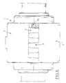
- Figure 1 shows a front view of the device according to the invention and particularly intended for gas pipelines.
- FIGS. 2A and 2B are details in longitudinal section explaining the locking effect produced by the grooves and the corresponding bar.
- Figure 3 is a longitudinal sectional view of the device according to the invention and in particular intended for gas pipes made of plastic.
- FIG. 4 is a half-view in longitudinal section schematically representing the fusion of electro-welding obtained after tensioning of the conducting wires.
- Figure 5 is a front view in partial longitudinal section showing a device according to the invention and in particular intended for water pipes.
- Figure 6 is a front view of such a device in place.
- Figure 7 is a side view with partial cross section of a device according to the invention and intended in particular for water pipes.
- Figures 8A and 8B are respectively a partial front view and a longitudinal sectional view along AA of a second alternative embodiment of the connection of the sleeve fixing flanges.
- FIGS. 9A and 9B are respectively a partial view in transverse section and a view in longitudinal section along BB of a third variant of this embodiment of the connection of the fixing flanges of the sleeve.
- Figure 10 is a front view of a half-shell of the sleeve having two electrical connection terminals.
- Figure 11 is a schematic representation of a safety device arranged in one of the connection terminals of a half-shell of the sleeve.
- the sleeve according to the invention will first be described in its application which is particularly suitable for gas pipes and shown in FIGS. 1 to 4.
- the sleeve being particularly suitable for sealing leakage areas at the pipe fittings, it has an interior part sufficient to contain the existing fitting (see Figures 3 and 4). It is composed of two plastic half-shells 2 and 2 ′ which are formed in a similar manner.
- the fixing of the two half-shells 2 and 2 ′ between them is carried out by the longitudinal flanges which they comprise one like the other.
- These brices consist of grooves 3 and 3 'which are intended to come to fit one into the other to form the assembled sleeve.
- the flutes of the flanges are perforated as shown in FIG. 2A by holes or orifices the diameter of which varies from one flute to the other.
- This leak-proof sleeve is sealed by several means, most of which are visible in FIGS. 3 and 4.
- each half-shell 2,2 ′ comprises two terminals 15,15 ′ for connection to the conductive wires 5,5 ′ accessible from the outside of the assembled sleeve.
- These terminals 15,15 ′ are intended to be connected to female sockets of a voltage generating device.
- one of the terminals 15 ′ comprises a stud 18 such as a female plug and a recess 16 near the stud 18, the recess 16 communicating with a groove 42 brought into the wall internal of the half-shell 2 and parallel to the wire 5 in FIG. 11.
- the part 17 comprises two male members opposite one another to respectively penetrate the stud 18 and the socket 19 above the stud 18 in order to establish an electrical connection.
- the part 17 carries a cartridge 40, one end of which is intended to be introduced into the recess 16 when a male member of the part 17 is engaged in the stud 18.
- the cartridge is filled with inert gas, sulfur exafloride for example.
- a conductive wire can also be placed near the joint plane of the two half-shells to make their connection by fusion of their surface.
- each half-shell is provided with two seals of large section 6, 6 ′, preferably made of polyurethane and which completes the sealing of the sleeve.
- the main cavity of the sleeve will be filled with a plastic material, preferably polyurethane, or a resin by injection as shown in 9 in Figure 4, the orifice d injection 11 then being mouth in a manner known per se.
- a plastic material preferably polyurethane, or a resin
- the orifice 11 is closed by a non-return, ball, valve or other plug.
- a non-return, ball, valve or other plug it suffices to inject the plastic or the resin.
- a static mixer will be used, mixing the components at the same time as its injection.
- plastic foam this may be polyurethane, silicone or the like.
- Figure 5 shows a sleeve of the type according to the invention but particularly intended to seal leaks to a pipe fitting intended to transport water and possibly metallic.
- this device has the same fixing and blocking arrangement by grooves 3, 3 ′ and by bar forming a corner 10.
- the groove or the lip is provided with a conductive wire in order to obtain the fixing by electro-fusion of the two half-shells.
- each half-shell each has a groove which comes opposite one another and into which is inserted a ribbon containing at least one conductive wire.
- one of the half-shells can be provided with positioning studs 8 which fit into corresponding orifices in the other half-shells and which are arranged on the contact surfaces other than those which are fluted.
- the sleeve thus formed may also include positioning fins 13 intended to center the connector 12 relative to the sleeve thus formed.
- the free space 9 is filled with polyurethane foam or equivalent and the orifice 11 for injection is closed.
- Figure 6 is a view similar to Figure 1 relating to the sleeve intended in particular to equip water pipes made of polyethylene or metal such as cast iron.
- Figure 7 shows the preferably trapezoidal section of the locking bars.
- the orifices made in the flanges of the half-shells are obviously of corresponding shape.
- FIGS. 8A to 9B show other alternative embodiments of the connection of the fixing flanges.
- the wedge effect is achieved by the wedge shape given to the fixing flanges 23, 23 ′ with which a connecting piece 20 is associated, comprising a cavity of shape complementary to that of two juxtaposed flanges.
- This connecting piece 20 is placed in translation on the flanges and is forced to lock when the corresponding inclined surfaces come to bear.
- the flanges 23, 23 ′ have a cross section of trapezoidal shape, the cavity of the part 20 being of complementary shape.
- the part 20 is blocked transversely on the flanges 23, 23 ′.
- the flanges 33 and 33 ′ also have a trapezoidal shape.
- the connecting piece 30 on the other hand only cooperates with one of the flanges 33 ′ and presents with respect to the other flange a substantial clearance in which is housed a blocking bar 31, the blocking being effected by force by effect of corner, the bar 31 filling the existing play and coming to block against the surface of one of the flanges and that of the cavity of the part 30.
- the sleeve in order to allow the sleeve to be filled with polyurethane foam or equivalent, it has at least one orifice forming a vent. Preferably, two vents are provided on either side of the filling orifice 11.
Landscapes
- Engineering & Computer Science (AREA)
- General Engineering & Computer Science (AREA)
- Mechanical Engineering (AREA)
- Rigid Pipes And Flexible Pipes (AREA)
- Pipe Accessories (AREA)
- Flanged Joints, Insulating Joints, And Other Joints (AREA)
- Quick-Acting Or Multi-Walled Pipe Joints (AREA)
Claims (10)
- Muffe aus Plastik zum Reparieren von undichten Stellen in einer Kanalisation, die dem Transport von Wasser, Gas oder Ähnlichem dient, wobei die Muffe zwei zylindrische Halbschalen aufweist, die sich aneinander entlang einer Verbindungsebene anschließen, wobei jede der Halbschalen zwei Befestigungsflansche nächstliegend zu den Längskanten der Halbschalen aufweist, wobei die Befestigungsflansche im Verkeilungseffekt zusammengesetzt sind, um die Halbschalen derart einstückig auszubilden, daß sie um die Kanalisation herum eine dichte Muffe bilden, die eine innere Aushöhlung aufweist, wobei die Muffe eine Dichteinrichtung gebildet von in Nähe der Verbindungsebene der Halbschalen angeordneten Leitungsdrähten aufweist, dadurch gekennzeichnet, daß die Muffe eine innere ringförmige Aushöhlung aufweist, daß eine Halbschale eine längliche Dichtrille (7) aufweist, die in Nahe zu den Längskanten angeordnet ist, und daß die andere Halbschale entweder eine längliche Dichtrille (7), die der anderen Rille gegenüber liegt, oder eine Dichtlippe, und wenigstens einen Leitungsdraht aufweist, der jeweils in einem in einer der Rillen angeordneten Band oder in der Rille oder in der Lippe angeordnet ist, um das Zusammenfügen des Plastiks und somit die Verbindung der beiden Halbschalen durchzuführen.
- Muffe gemäß Anspruch 1, dadurch gekennzeichnet, daß sie aus Polyethylen gebildet ist.
- Muffe gemäß Anspruch 1, dadurch gekennzeichnet, daß die halbkreisförmigen Kanten jeder Halbschale, die mit dem Rohrstutzen in Kontakt kommen, mit verformbaren Riefen (4, 4′) versehen sind, die eine Dichteinrichtung durch Druckverformung der Riefen (4, 4′) bilden.
- Muffe gemäß den Ansprüchen 1 bis 3, dadurch gekennzeichnet, daß sie eine andere Dichteinrichtung aufweist, die aus mindestens zwei Dichtungen (6, 6′) mit bedeutendem Querschnitt vorzugsweise aus Polyurethan besteht, und die im Halbkreis in eine Rille jeder Halbschale eingesetzt wird.
- Muffe gemäß irgendeinem der vorherigen Ansprüche und für Kanalisationen aus Plastik, insbesondere zum Transport von Gas, bestimmt, dadurch gekennzeichnet, daß sie eine Dichteinrichtung aufweist, die aus Leitungsdrähten (5, 5′) gebildet ist, die in Nähe zu den Flächen angeordnet sind, die mit dem Rohrstutzen in Kontakt kommen sollen.
- Muffe gemäß irgendeinem der vorherigen Ansprüche, dadurch gekennzeichnet, daß sie auf einer ihrer Halbschalen Positionierungsstifte (8) aufweist, die mit den entsprechenden Öffnungen auf der anderen Halbschale zusammenwirken.
- Muffe gemäß Anspruch 1, dadurch gekennzeichnet, daß der Verkeilungseffekt durch in den Flanschen ausgebildete Riffelungen (3, 3′) hervorgerufen wird, wobei die nebeneinander liegenden Flanschriffelungen ineinander greifen und sie mit Öffnungen von verschiedenen Größen versehen sind, die leicht zueinander versetzt sind, und die dazu bestimmt sind, einen Blockierstab aufzunehmen (10), dessen Querschnitt sich vom Kopf zu seinem äußeren Ende hin verjüngt, und der eine zusätzliche Blockierung durch Materialdruck bewirkt.
- Muffe gemäß Anspruch 1, dadurch gekennzeichnet, daß die Flansche (23, 23′) einen trapezförmigen Querschnitt und einen keilförmigen Längsschnitt haben, und daß sie miteinander durch ein Teil (20) verbunden sind, das eine Aushöhlung in ergänzender Form aufweist.
- Muffe gemäß Anspruch 1, dadurch gekennzeichnet, daß die Flansche (33,33′) einen trapezförmigen Querschnitt und einen keilförmigen Längsschnitt haben, und daß sie miteinander durch ein Teil (30) verbunden sind, das eine Aushöhlung aufweist, die mit erheblichem Spielraum die Flansche (33, 33′) aufnimmt, welche durch einen Stab (31) blockiert werden, der eine zu dem in der Aushöhlung des Teils (30) herrschenden Spielraum ergänzende Form hat, und der in diesen eingeführt ist.
- Muffe gemäß Anspruch 5, dadurch gekennzeichnet, daß jede Halbschale zwei in Nähe zu den Flächen, die mit dem Rohrstutzen in Kontakt kommen sollen, angeordnete Anschlußklemmen (15, 15′) an den Leitungsdrähten aufweist, die von außen der zusammengestzten Muffe zugänglich sind, wobei eine der Klemmen (15′) Einrichtungen besitzt zur Aufnahme eines Sicherungsorgans (17), das zwischen der Klemme und einer Spannungsspeisungsdose (19) angeordnet ist, wobei das Sicherungsorgan eine elektrische Verbindung zwischen der Klemme und der Dose bildet und eine Hütchenpatrone (40) gefüllt mit reaktionslosem Gas aufweist, die dazu bestimmt ist, sich im Inneren der Muffe während der Verbindung der Dose mit der Klemme zu leeren.
Applications Claiming Priority (3)
| Application Number | Priority Date | Filing Date | Title |
|---|---|---|---|
| FR9008684A FR2664360B1 (fr) | 1990-07-09 | 1990-07-09 | Manchon de reparation de fuites dans une canalisation. |
| FR9008684 | 1990-07-09 | ||
| PCT/FR1991/000550 WO1992001190A2 (fr) | 1990-07-09 | 1991-07-08 | Manchon de reparation de fuites dans une canalisation |
Publications (2)
| Publication Number | Publication Date |
|---|---|
| EP0538351A1 EP0538351A1 (de) | 1993-04-28 |
| EP0538351B1 true EP0538351B1 (de) | 1994-12-07 |
Family
ID=9398499
Family Applications (1)
| Application Number | Title | Priority Date | Filing Date |
|---|---|---|---|
| EP91913026A Expired - Lifetime EP0538351B1 (de) | 1990-07-09 | 1991-07-08 | Hülse zum reparieren von lecken in einer rohrleitung |
Country Status (5)
| Country | Link |
|---|---|
| EP (1) | EP0538351B1 (de) |
| DE (1) | DE69105735T2 (de) |
| ES (1) | ES2068598T3 (de) |
| FR (1) | FR2664360B1 (de) |
| WO (1) | WO1992001190A2 (de) |
Families Citing this family (8)
| Publication number | Priority date | Publication date | Assignee | Title |
|---|---|---|---|---|
| FR2699984B1 (fr) * | 1992-12-24 | 1995-02-17 | Gaz De France | Procédé et dispositif pour la réparation, en charge, de canalisations en matière plastique. |
| GB0010329D0 (en) | 2000-04-28 | 2000-06-14 | Bg Intellectual Pty Ltd | Securing shell assemblies to pipelines |
| RU2191317C2 (ru) * | 2001-01-05 | 2002-10-20 | Лапицкая Татьяна Валентиновна | Способ ремонта трубопроводов |
| RU2256843C1 (ru) * | 2003-11-24 | 2005-07-20 | Открытое акционерное общество "Научно-производственное объединение "Стеклопластик" | Многослойная упрочняющая защита |
| ES2342863B1 (es) * | 2007-05-14 | 2011-05-03 | Uralita Sistemas De Tuberias, S.A. | Sistema de saneamiento. |
| GB201216665D0 (en) * | 2012-08-30 | 2012-10-31 | Beech David | Enclosure means for pipes, cables and wires |
| CA2924876A1 (en) * | 2012-09-21 | 2014-03-27 | Universitetet I Stavanger | Tool for leak point identification and new methods for identification, close visual inspection and repair of leaking pipelines |
| RU199972U1 (ru) * | 2020-05-18 | 2020-09-30 | Общество с ограниченной ответственностью "Агентство ГЛИНТ" | Муфта для трубопровода |
Family Cites Families (11)
| Publication number | Priority date | Publication date | Assignee | Title |
|---|---|---|---|---|
| GB177939A (en) * | 1921-02-16 | 1922-04-13 | Richard Cooke | An improved device for repairing gas, water, or steam pipes, applicable also for fitting branch pipes thereto |
| GB606816A (en) * | 1945-11-15 | 1948-08-20 | Sidney George Parsons | Improvements in or relating to clips for repairing pipes |
| US3350755A (en) * | 1965-05-19 | 1967-11-07 | John R Hanner | Wedge lock clamp and fastener device |
| NL7014125A (de) * | 1970-09-24 | 1972-03-28 | ||
| DE3065242D1 (en) * | 1979-04-05 | 1983-11-17 | Brickhouse Dudley Plc | Method for joining together thermoplastics pipes and pipe fittings |
| GB2080916B (en) * | 1980-07-29 | 1984-08-08 | Encapsulation Services Ltd | Repairing a leak in a pipe |
| FR2516439A1 (fr) * | 1981-11-13 | 1983-05-20 | Armosig | Procede de soudage electrique de pieces en matiere plastique, en particulier pour canalisations de fluides et manchons de raccordement pour de telles canalisations |
| FR2519731B1 (fr) * | 1982-01-08 | 1986-02-14 | Lamotte Jean Noel | Procede permettant d'etancher une fuite sur une canalisation et canalisation etanchee conformement a ce procede |
| GB8403596D0 (en) * | 1984-02-10 | 1984-03-14 | Alh Syst Ltd | Pipe seal |
| ATE36906T1 (de) * | 1984-08-08 | 1988-09-15 | Fischer Ag Georg | Anbohrformstueck zum anschluss einer abzweigleitung. |
| FR2605378B1 (fr) * | 1986-10-17 | 1991-01-04 | Clement Raymond | Dispositif d'intervention sur connexions de canalisations en service |
-
1990
- 1990-07-09 FR FR9008684A patent/FR2664360B1/fr not_active Expired - Fee Related
-
1991
- 1991-07-08 WO PCT/FR1991/000550 patent/WO1992001190A2/fr not_active Ceased
- 1991-07-08 EP EP91913026A patent/EP0538351B1/de not_active Expired - Lifetime
- 1991-07-08 ES ES91913026T patent/ES2068598T3/es not_active Expired - Lifetime
- 1991-07-08 DE DE69105735T patent/DE69105735T2/de not_active Expired - Fee Related
Also Published As
| Publication number | Publication date |
|---|---|
| WO1992001190A3 (fr) | 1992-07-09 |
| DE69105735D1 (de) | 1995-01-19 |
| FR2664360B1 (fr) | 1992-11-06 |
| WO1992001190A2 (fr) | 1992-01-23 |
| DE69105735T2 (de) | 1995-04-13 |
| EP0538351A1 (de) | 1993-04-28 |
| FR2664360A1 (fr) | 1992-01-10 |
| ES2068598T3 (es) | 1995-04-16 |
Similar Documents
| Publication | Publication Date | Title |
|---|---|---|
| EP0382593B1 (de) | Verbindungssystem zum Verschweissen von ineinandersteckbaren rohrförmigen Teilen | |
| FR2823283A1 (fr) | Raccord etanche | |
| FR2760064A1 (fr) | Raccord traversant et systeme a double confinement de fluide | |
| EP0942507B1 (de) | Abgedichtetes Gehäuse einer Vorrichtung mit Zugang zu einem Kabel | |
| CA2235107C (fr) | Manchon modulaire pour la protection, la reparation ou la renovation d'une canalisation | |
| WO1992001190A2 (fr) | Manchon de reparation de fuites dans une canalisation | |
| EP0346163A1 (de) | Vorrichtung zur Verbindung von Rohren, insbesondere für Gas | |
| FR2688571A1 (fr) | Dispositif de raccordement pour tuyaux. | |
| EP0499754B1 (de) | Verschluss zum dichten Befestigen eines elektrischen Kabels in einer Öffnung und Kabelschutzmuffe mit solchen Verschlüssen | |
| EP0695014B1 (de) | Garnitur für die Verbindung von Niederspannungsenergiekabeln | |
| FR2475306A1 (fr) | Boite de jonction universelle pour cables de telecommunications ou de puissance | |
| EP1062449A1 (de) | Detektierbare kunststoff-rohrleitung und ihre verbindungsmittel | |
| FR2755797A1 (fr) | Ensemble a haute tension a elements separables | |
| FR2728049A1 (fr) | Dispositif de raccordement d'une extremite d'un tube en matiere thermoplastique renforcee | |
| FR2699984A1 (fr) | Procédé et dispositif pour la réparation, en charge, de canalisations en matière plastique. | |
| FR2886475A1 (fr) | Connecteur blinde pour conducteurs electriques. | |
| FR2698494A1 (fr) | Manchon pour connecteur destiné à une traversée étanche et ensemble le comportant. | |
| FR2519731A1 (fr) | Procede permettant d'etancher une fuite sur une canalisation et canalisation etanchee conformement a ce procede | |
| FR2650049A1 (fr) | Dispositif de blocage dans un conduit tubulaire, notamment dans un tube pour cables | |
| FR2640720A1 (fr) | Raccord etanche aux liquides pour tuyau flexible non metallique et tubulure flexible non metallique | |
| FR2814597A1 (fr) | Element d'etancheite pour un dispositif de connexion electrique | |
| WO2007017560A1 (fr) | Dispositif dεtancheite de connecteur | |
| FR2504309A1 (fr) | Dispositif de protection etanche des epissures de cables telephoniques | |
| FR2724780A1 (fr) | Bague support de conducteurs electriques destinee a etre utilisee pour la traversee de cloisons | |
| FR2734687A3 (fr) | Joint d'etancheite pour un boitier |
Legal Events
| Date | Code | Title | Description |
|---|---|---|---|
| PUAI | Public reference made under article 153(3) epc to a published international application that has entered the european phase |
Free format text: ORIGINAL CODE: 0009012 |
|
| 17P | Request for examination filed |
Effective date: 19930208 |
|
| AK | Designated contracting states |
Kind code of ref document: A1 Designated state(s): DE ES FR GB IT |
|
| 17Q | First examination report despatched |
Effective date: 19930802 |
|
| GRAA | (expected) grant |
Free format text: ORIGINAL CODE: 0009210 |
|
| AK | Designated contracting states |
Kind code of ref document: B1 Designated state(s): DE ES FR GB IT |
|
| REF | Corresponds to: |
Ref document number: 69105735 Country of ref document: DE Date of ref document: 19950119 |
|
| ITF | It: translation for a ep patent filed | ||
| GBT | Gb: translation of ep patent filed (gb section 77(6)(a)/1977) |
Effective date: 19950310 |
|
| REG | Reference to a national code |
Ref country code: ES Ref legal event code: FG2A Ref document number: 2068598 Country of ref document: ES Kind code of ref document: T3 |
|
| PGFP | Annual fee paid to national office [announced via postgrant information from national office to epo] |
Ref country code: GB Payment date: 19950707 Year of fee payment: 5 |
|
| PGFP | Annual fee paid to national office [announced via postgrant information from national office to epo] |
Ref country code: FR Payment date: 19950728 Year of fee payment: 5 |
|
| PLBE | No opposition filed within time limit |
Free format text: ORIGINAL CODE: 0009261 |
|
| STAA | Information on the status of an ep patent application or granted ep patent |
Free format text: STATUS: NO OPPOSITION FILED WITHIN TIME LIMIT |
|
| 26N | No opposition filed | ||
| PGFP | Annual fee paid to national office [announced via postgrant information from national office to epo] |
Ref country code: DE Payment date: 19960701 Year of fee payment: 6 |
|
| PG25 | Lapsed in a contracting state [announced via postgrant information from national office to epo] |
Ref country code: GB Effective date: 19960708 |
|
| PGFP | Annual fee paid to national office [announced via postgrant information from national office to epo] |
Ref country code: ES Payment date: 19960709 Year of fee payment: 6 |
|
| GBPC | Gb: european patent ceased through non-payment of renewal fee |
Effective date: 19960708 |
|
| PG25 | Lapsed in a contracting state [announced via postgrant information from national office to epo] |
Ref country code: FR Effective date: 19970328 |
|
| REG | Reference to a national code |
Ref country code: FR Ref legal event code: ST |
|
| PG25 | Lapsed in a contracting state [announced via postgrant information from national office to epo] |
Ref country code: ES Free format text: THE PATENT HAS BEEN ANNULLED BY A DECISION OF A NATIONAL AUTHORITY Effective date: 19970709 |
|
| PG25 | Lapsed in a contracting state [announced via postgrant information from national office to epo] |
Ref country code: DE Free format text: LAPSE BECAUSE OF NON-PAYMENT OF DUE FEES Effective date: 19980401 |
|
| REG | Reference to a national code |
Ref country code: ES Ref legal event code: FD2A Effective date: 20001204 |
|
| PG25 | Lapsed in a contracting state [announced via postgrant information from national office to epo] |
Ref country code: IT Free format text: LAPSE BECAUSE OF NON-PAYMENT OF DUE FEES Effective date: 20050708 |