EP0538488A1 - Streifenkodeleser und spielzeug mit einem solchen leser - Google Patents
Streifenkodeleser und spielzeug mit einem solchen leser Download PDFInfo
- Publication number
- EP0538488A1 EP0538488A1 EP92909845A EP92909845A EP0538488A1 EP 0538488 A1 EP0538488 A1 EP 0538488A1 EP 92909845 A EP92909845 A EP 92909845A EP 92909845 A EP92909845 A EP 92909845A EP 0538488 A1 EP0538488 A1 EP 0538488A1
- Authority
- EP
- European Patent Office
- Prior art keywords
- bar code
- data
- noise
- bar
- counted value
- Prior art date
- Legal status (The legal status is an assumption and is not a legal conclusion. Google has not performed a legal analysis and makes no representation as to the accuracy of the status listed.)
- Ceased
Links
Images


Classifications
-
- G—PHYSICS
- G06—COMPUTING OR CALCULATING; COUNTING
- G06K—GRAPHICAL DATA READING; PRESENTATION OF DATA; RECORD CARRIERS; HANDLING RECORD CARRIERS
- G06K7/00—Methods or arrangements for sensing record carriers, e.g. for reading patterns
- G06K7/10—Methods or arrangements for sensing record carriers, e.g. for reading patterns by electromagnetic radiation, e.g. optical sensing; by corpuscular radiation
- G06K7/10544—Methods or arrangements for sensing record carriers, e.g. for reading patterns by electromagnetic radiation, e.g. optical sensing; by corpuscular radiation by scanning of the records by radiation in the optical part of the electromagnetic spectrum
- G06K7/10821—Methods or arrangements for sensing record carriers, e.g. for reading patterns by electromagnetic radiation, e.g. optical sensing; by corpuscular radiation by scanning of the records by radiation in the optical part of the electromagnetic spectrum further details of bar or optical code scanning devices
- G06K7/10851—Circuits for pulse shaping, amplifying, eliminating noise signals, checking the function of the sensing device
-
- G—PHYSICS
- G06—COMPUTING OR CALCULATING; COUNTING
- G06K—GRAPHICAL DATA READING; PRESENTATION OF DATA; RECORD CARRIERS; HANDLING RECORD CARRIERS
- G06K7/00—Methods or arrangements for sensing record carriers, e.g. for reading patterns
- G06K7/10—Methods or arrangements for sensing record carriers, e.g. for reading patterns by electromagnetic radiation, e.g. optical sensing; by corpuscular radiation
- G06K7/14—Methods or arrangements for sensing record carriers, e.g. for reading patterns by electromagnetic radiation, e.g. optical sensing; by corpuscular radiation using light without selection of wavelength, e.g. sensing reflected white light
Definitions
- the present invention relates to a bar code reader and a game set using the same. More particularly, the present invention relates to an improved bar code reader capable of removing various types of noise included in bar code data and a game set using the same.
- U. S Patent No. 4, 729, 564 (hereinafter referred to as a first prior art document), Japanese Patent Laid Open Gazette No. 11183/1990 (hereinafter referred to as a second prior art document), and Japanese Patent Laid-Open Gazette No. 23592/1990 (hereinafter referred to as a third prior art document) disclose a game set playing various games on the basis of bar code data read from a bar code card.
- the first to third prior art documents utilize the bar code data read from the bar code card by a bar code reader without any modification and fail to disclose a technique for removing various types of noise included in the bar code data. Therefore, erroneous data is liable to be inputted to the game set by the bar code data including the noise. Particularly in the field of the game set, lower cost is required. Accordingly, it is impossible to use, as the bar code reader, high-cost and high-precision one. Consequently, it is highly possible that noise is included in the bar code data read by the bar code reader.
- the bar code card produced by the player himself or herself is generally inferior in state in many cases. Accordingly, it is very highly possible that noise is included in the bar code data read by the bar code reader. For example, when a bar code cut from a package of a commodity is bonded to a card and used, dust is liable to adhere to the bar code by adhesives squeezed from the adhesive surface. In this case, the dust adhering to the bar code is liable to be erroneously recognized as a part of a black or white bar included in the bar code. In addition, when the bar code attached to the commodity is damaged from the beginning, a read error occurs in a damaged portion.
- the shape of each of the bars in the bar code is deformed by distortion of an optical system in the copying machine. Particularly when copying of the bar code is repeated many times, the degree of deformation of each of the bars is increased. In this case, the width of each of the bars is not normally read, thereby causing a read error.
- the above described game set in the forth prior art document utilizes the bar code data read from the bar code card without any modification and fails to disclose a technique related to signal processing for removing noise included in the bar code data, similarly to the above described first to third prior art documents. Therefore, the above described game set in the fourth prior art document has the disadvantage in that a read error frequently occurs, whereby the interest in the game is lost.
- an object of the present invention is to provide an improved bar code reader capable of reliably detecting various types of noise included in bar code data and improving the reading precision of a bar code even if a relatively simple and low-cost optical reader is used.
- Another object of the present intention is to provide an improved bar code reader capable of reliably detecting noise in bar code data and nullifying the same.
- Still another object of the present invention is to provide an improved bar code reader capable of correcting distortion of the width of each of bars included in a bar code.
- a further object of the present invention is to provide an improved bar code reader capable of correcting a read error in a bar code due to the change in the speed of movement of a bar code record medium.
- a still further object of the present invention is to provide an improved game set capable of reliably detecting and nullifying various types of noise included in bar code data inputted and using the inputted bar code data for processing for a game.
- a bar code reader is a device for reading bar code data from a bar code record medium on which a bar code formed by alternately arranging first bars having a relatively bright color and second bars having a relatively dark color and representing a front identification symbol and a rear identification symbol and coded data arranged between the front identification symbol and the rear identification symbol depending on the change in the width of each of the bars is recorded, comprising an optical system comprising a light emitting portion and a light receiving portion for optically reading the change in the width of each of the bars, when the relative positional relationship between the light emitting portion and the light receiving portion and the bar code record medium is changed, in relation to the change in the relative positional relationship, counted value data converting means for converting the change in the width of each of the bars read by the optical system into counted value data for each bar, temporary storing means for temporarily storing the counted value data for each bar obtained by the conversion by the counted value data converting means, judging means for judging whether or not noise is included in the bar code data
- the number of samples of the counted value data stored in the temporary storing means is compared with a predetermined number of samples, thereby to make it possible to reliably judge whether or not noise is included in the bar code data. Consequently, the bar code data can be prevented from being decoded in a state where noise is included, resulting in improved reading precision.
- the counted value data for the second bar which exists in the end out of the counted value data for the respective bars stored in the temporary storing means and the counted value data for the first bar which is the closest in the direction of the front identification symbol or in the direction of the rear identification symbol as viewed from the second bar are compared with each other, thereby to judge whether or not the second bar which exists in the end is noise.
- the counted value data corresponding to the second bar is nullified. Consequently, noise which exists outside of the front identification symbol and the rear identification symbol can be reliably nullified.
- the counted value data for the second bar which exists in the end out of the counted value data for the respective bars stored in the temporary storing means and the counted value data for the second bar which is the closest to this bar are compared with each other, thereby to judge whether or not the second bar which exists in the end is noise.
- the counted value data corresponding to the noise is nullified. Consequently, noise which exist outside of the front identification symbol and the rear identification symbol can be reliably nullified.
- the counted value data for the bar having the smallest width out of the counted value data for the respective bars stored in the temporary storing means is removed as noise so that noise which exists between the front identification symbol and the rear identification symbol is removed.
- data related to distortion of the widths of the first and second bars in the bar code record medium is operated on the basis of the counted value data of the front identification symbol and/or the rear identification symbol stored in the temporary storing means, and the operated data related to distortion and the counted value data for each of the first bars or the counted value data for each of the second bars which is stored in the temporary storing means are operated so that the distortion of the widths of the first and second bars in the bar code data is corrected.
- the bar code data is decoded for each predetermined very small section on the basis of a combination of the counted value data corresponding to the widths of the plurality of bars in close proximity to each other so that a read error caused by the change in the speed of the bar code record medium is corrected.
- an image signal of a bar code pattern of the bar code data decoded by the decoding means and/or a numeral corresponding to the bar code data is generated and applied to image displaying means so that the results of the decoding of the bar code data are displayed and outputted such that they can be visually recognized.
- a user of the bar code reader can confirm whether or not the bar code is accurately decoded.
- the bar code data decoded by the decoding means is utilized as input data for processing for a game, and an image signal for the progress of the game is generated on the basis of the input data and applied to the image displaying means.
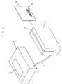
- Fig. 1 is a perspective view showing the construction of one embodiment of a bar code reader according to the present invention.
- Fig. 2 is a block diagram showing the construction of an electric circuit portion of the bar code reader shown in Fig. 1.
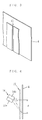
- Fig. 3 is a perspective view showing the construction of a slit contained within the bar code reader shown in Fig. 1.
- Fig. 4 is a perspective view showing the arrangement relationship of a light projecting and receiving unit contained within the bar code reader shown in Fig. 1.
- Fig. 5 is an illustration showing one example of a JAN (Japanese Article Number) code.
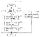
- Fig. 6 is a flow chart for explaining operations of the bar code reader shown in Fig. 1 and 2.
- Fig. 7 is a flow chart showing a noise removing operation executed in the flow chart shown in Fig. 6 in more detail.
- Fig. 8 is a flow chart showing a noise removing operation of noise before a start guard bar executed in the flow chart shown in Fig. 7 in more detail.
- Fig. 9 is a flow chart showing another noise removing operation executed in the flow chart shown in Fig. 7 in more detail.
- Fig. 10 is a flow chart showing a correcting operation of each bar executed in the flow chart shown in Fig. 6 in more detail.
- Fig. 11 is a flow chart showing a decoding operation of a JAN code executed in the flow chart shown in Fig. 6 in more detail.
- Fig. 12 is a perspective view showing the construction of a game set according to one embodiment of the present invention which plays a game using a bar code card.
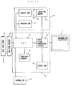
- Fig. 13 is a block diagram showing the construction of an electric circuit portion of the game set shown in Fig. 12.
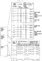
- Fig. 14 is a memory map showing an address space of a memory used in the game set shown in Fig. 13.
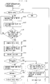
- Fig. 15 is a flow chart showing a first portion of a game processing operation executed by the game set shown in Figs. 12 and 13.
- Fig. 16 is a flow chart showing a second portion of the game processing operation executed by the game set shown in Figs. 12 and 13.
- Fig. 17 is a flow chart showing a third portion of the game processing operation executed by the game set shown in Figs. 12 and 13.
- Fig. 18 is a flow chart showing an interruption processing operation executed by the game set shown in Figs. 12 and 13.
- Fig. 1 is a perspective view showing the construction of one embodiment of a bar code reader according to the present invention.
- a bar code reader 1 is connected to a data processor 3 through a connection cable 2.
- a sliding guide groove 11 extending along the length of the bar code reader 1 is formed in the center of the upper surface of the bar code reader 1.
- a bar code card 4 is slid within the sliding guide groove 11 with it being held in user's hand.
- the bar code reader 1 optically reads a bar code 41 recorded on the bar code card 4.
- Bar code data read by the bar code reader 1 is applied to the data processor 3 through the connection cable 2.
- the data processor 3 processes the applied bar code data, and displays the results of the processing on a display 31 constituted by, for example, a liquid crystal display.
- Fig. 2 is a block diagram showing the construction of an electric circuit portion of the bar code reader shown in Fig. 1.
- the bar code reader 1 comprises a driving circuit 12, an amplifier circuit 13, and a light projecting and receiving unit 14.
- the light projecting and receiving unit 14 is constructed as a compound element obtained by integrally joining a light projecting element 14a including, for example, a light emitting diode (LED) and a light receiving element 14b including, for example, a photodiode to each other.
- the light projecting element 14a is driven by power supplied from the driving circuit 12.
- a detection signal of the light receiving element 14b is amplified and wave-shaped by the amplifier circuit 13 and then, is applied to the data processor 3 through the connection table 2.
- a slit 15 is provided so as to be opposed to the bar code card 4 inside of the sliding guide groove 11.
- This slit 15 extends in a direction orthogonal to the direction of sliding of the bar code card 4.
- the light projecting and receiving unit 14 is so arranged as to be inclined at a predetermined angle to the slit 15, as shown in Fig. 4.
- the optical axes of the light projecting element 14a and the light receiving element 14b are respectively inclined at predetermined angles to the slit 15, and a surface including the optical axis of the light projecting element 14a and the optical axis of the light receiving element 14b extends along the slit 15.
- the slit 15 is provided between the light projecting and receiving unit 14 and the bar code card 4, thereby to make it possible to improve the reading precision of the bar code 41.
- the bar code is read through a hole, the above described noise is read when the noise passes in front of the hole.
- the bar code is read through the slit, the area of the noise relative to the area of bars detected through the slit is small, so that a noise detecting level is lowered or a counted value corresponding to the noise is made significantly small. Therefore, the noise is not read, resulting in improved reading precision.
- the light projecting and receiving unit 14 is so arranged as to be inclined at a predetermined angle to the slit 15, thereby to make it possible to enlarge a range d in which light of the light projecting element 14a is irradiated on the bar code card 4. As a result, a range in which the bar code card 4 receives light is enlarged, whereby more reflected light from the bar code card 4 can be incident on the light receiving element 14b.
- the data processor 3 comprises a display 31, an input-output (hereinafter referred to as IO) interface 32, a CPU 33, a ROM 34, and a RAM 35.
- the IO interface 32 controls input and output of a signal between the CPU 33 and the bar code reader 1.
- the CPU 33 performs a predetermined operation (for example, an operation shown in Fig. 6) in accordance with an operation program stored in the ROM 34.
- the ROM 34 stores an operation program for the CPU 33 in a nonvolatile manner.
- the RAM 35 stores various data required for data processing by the CPU 33.
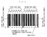
- Fig. 5 is an illustration showing one example of the bar code read by the bar code reader shown in Fig. 1.
- Fig. 5 illustrates a JAN (Japanese Article Number) code used most commonly in Japan as one example of the bar code.
- the JAN code comprises first and second data areas, a start guard bar (a front identification symbol), an intermediate guard bar (an intermediate identification symbol), and an end guard bar (a rear identification symbol).
- the first data area is arranged between the start guard bar and the intermediate guard bar.
- the second data area is arranged between the intermediate guard bar and the end guard bar.
- the start guard bar, the intermediate guard bar, and the end guard bar respectively represent the front end, the middle, and the rear end of the bar code.
- Each of them is constituted by two black bars and one white bar arranged between the black bars.
- the two black bars and the one white bar constituting each of the guard bars are so selected as to be equal in width to each other.
- the above described first data area comprises six data code portions D1 to D6.
- the above described second data area comprises five data code portions D7 to D11, and a check code portion CD.
- Each of the data code portions D1 to D11 and the check code portion CD can be divided into seven segment regions.
- a numerical value assigned to the code portion is specified depending on which of the seven segment regions is painted black, that is, what value each of the widths of white and black bars arranged in the same code portion has.
- each of the data code portions D1 to D11 and the check code portion CD is so prescribed as to represent a numerical code by a combination of two white bars and two black bars.
- each of the data code portions D1 to D6 in the first data area is so prescribed that the four bars are arranged in the order of the "white bar, black bar, white bar and black bar” as viewed from the start guard bar
- each of the data code portions D7 to D11 and the check code portion CD in the second data area is so prescribed that the four bars are arranged in the order of the "black bar, white bar, black bar and white bar” as viewed from the intermediate guard bar.
- the data code portions D1 to D11 and the check code portion CD can respectively represent numerical values from 0 to 9 (decimal numbers).
- the check code portion CD in the second data area is used as a check digit for checking to see whether or not the results of reading with respect to each of the data code portions D1 to D11 is correct. Specifically, a numerical value of this check digit is so selected as to be equal to the results of operation obtained when a predetermined operation is performed on the results of the reading with respect to each of the data code portions D1 to D11.
- Fig. 5 shows a so-called normal JAN code out of JAN codes.
- a so-called short JAN code in which the number of bars arranged in each data area is smaller than that in the normal JAN code shown in Fig. 5 exists in addition to the normal JAN code out of the JAN codes. It is goes without saying that the present invention is also available for such a short JAN code. In addition, it should be previously noted that the present invention is available for not only the JAN codes but also other bar codes.
- the light projecting element 14a is lighted up by the driving circuit 12, so that the bar code reader 1 enters a bar code readable state.
- the bar code card 4 is inserted into the sliding guide groove 11 of the bar code reader 1
- light emitted from the light projecting element 14a is reflected from the surface of the bar code card 4.
- the reflected light from the bar code card 4 is incident on the light receiving element 14b, to be converted into an electric signal. Consequently, the level of the detection signal outputted from the light receiving element 14b varies according to the brightness and darkness of the surface of the bar code card 4, that is, the bar code 41 recorded on the bar code card 4.
- the data processor 3 also enters an operable state in response to the application of the power, to perform operations shown in Fig. 6.
- the CPU 33 judges whether or not the level of a detection output of the bar code reader 1 is a white level (a level in a case where a bright color is read). Specifically, the CPU 33 judges whether or not a white region on the bar code card 4 is detected by the light receiving element 14b. At this time, if the bar code card 4 is not inserted into the sliding guide groove 11 of the bar code reader 1, no reflected light is incident on the light receiving element 14b. Therefore, the level of the detection output of the bar code reader 1 becomes a black level (a level in a case where a dark color is read). The CPU 33 repeats the judging operation in the step S101 until the level of the detection output of the bar code reader 1 becomes the white level.
- the program proceeds to the step S102.
- the CPU 33 measures the time width in which the white level of the detection output of the bar code reader 1 is maintained, that is, the time width of the first white data.
- the time width is measured by counting the above described time width in which the white level is maintained by a counter in the CPU 33. A counted value of this counter corresponds to the width of a white region on the bar code card 4 which exists before the start guard bar.
- the program then proceeds to the step S103.
- the CPU 33 loads the results of the measurement in the step S102 in, for example, a register in the RAM 35.
- the program then proceeds to the step S104.
- the CPU 33 judges whether or not the change in the level of the detection output of the bar code reader 1 is stopped for not less than a predetermined time period. If the level of the detection output of the bar code reader 1 is changed before the predetermined time period has elapsed, the program proceeds to the step S102 again.
- the CPU 33 measures the time width in which the black level of the detection output of the bar code reader 1 is maintained, that is, the time width of the first black data by the counter in the CPU 33 this time.
- a counted value of the counter at this time corresponds to the width of the first black data in the bar code card 4 (noise which exists before the start guard bar or the first black bar in the start guard bar).
- This counted value of the counter is loaded in the register in the RAM 35 in the step S103. Thereafter, the operations in the steps S102 to S104 are repeated until the change in the level of the detection output of the bar code reader 1 is stopped for not less than a predetermined time period. Consequently, the widths of the white data and the black data read from the bar code 41 are measured, and are loaded in the register in the RAM 35.
- the CPU 33 removes noise from the bar code data loaded in the register in the RAM 35.
- the details of a subroutine in this step S105 are shown in Fig. 7.
- the CPU 33 first judges in the step S201 whether or riot the number of samples in the bar code data loaded in the register in the RAM 35 (the total number of white data and black data) coincides with a predetermined prescribed number "61".
- a predetermined prescribed number "61" As apparent from Fig. 5, in the normal JAN code, it is prescribed that the sum of white regions before the start guard bar and behind the end guard bar (two), the number of white bars (29) and the number of black bars (30) is 61. Consequently, the number of samples in normal bar code data including no noise must be 61.
- the CPU 33 judges that noise is included in the bar code data, to remove the noise from the bar code data.
- the CPU 33 first performs an operation of removing noise which exists in the white region before the start guard bar. The details of a subroutine in this step S202 are shown in Fig. 8.
- the CPU 33 first judges in the step S301 whether or not twice a width B1 of black data on the head end of the bar code data loaded in the RAM 35 (B1 x 2) is larger than a width W1 of the subsequent white data. If the above described value (B1 x 2) is larger than the above described width W1, the program proceeds to the step S302. In the step S302, the CPU 33 removes as noise the black data on the head end of the bar code data. As described above, the widths of the black bars and the white bar in the start guard bar are so selected as to be equal to each other. In the normal bar code data, therefore, the width B1 of the black data on the head end and the width W1 of the subsequent white data must be approximately equal to each other.
- the CPU 33 removes as noise the black data on the head end.
- the program then proceeds to the step S303.
- the CPU 33 judges whether or not the number of samples in the bar code data after the noise removal is larger than the above described prescribed number "61". If the number of samples becomes the prescribed number "61", the CPU 33 judges that all noise is removed from the bar code data, to be returned to the operations shown in Fig. 7. On the other hand, when the number of samples in the bar code data is still larger than the prescribed number "61", the CPU 33 is returned to the operation in the step S301 again, to repeat the same noise removing operation as described above.
- the program proceeds to an operation in the step S304 from the step S301.
- the CPU 33 judges whether or not the absolute value of the difference between the width B1 of the black data on the head end and the width B2 of the subsequent black data
- the widths of the two black bars in the start guard bar are so selected as to be equal to each other. In the normal bar code data, therefore, the absolute value
- the program proceeds to the step S302.
- the CPU 33 removes as noise the black data on the head end. Thereafter, the CPU 33 performs the above described operation in the step S303.
- step S203 the CPU 33 removes noise which exists in the white region behind the end guard bar this time.
- Operations of a subroutine in this step S203 are approximately the same as the operations of the subroutine in the step S202 (see Fig. 8) and thus, the detailed description thereof is omitted in this specification so as to avoid the overlapped description.
- the bar code data loaded in the register in the RAM 35 are observed in the order from the front in the above described step S202, the bar code data is observed in the order from the rear in the step S203.
- step S204 the CPU 33 removes noise which exists between the start guard bar and the end guard bar.
- the details of a subroutine in this step S204 are shown in Fig. 9. Referring to Fig. 9, the CPU 33 first judges in the step S401 whether or not the number of samples in the bar code data coincides with the above described prescribed number "61". If the number of samples coincides with the prescribed number "61”, the CPU 33 judges that no noise exists in the bar code data, to be returned to the operations shown in Fig. 7 without performing a noise removing operation. On the other hand, if the number of samples is larger than the above described prescribed number "61", the program proceeds to the step S402.
- the CPU 33 judges that data having the smallest counted value out of all the samples is noise and removes the same.
- the noise removing operation in the step S402 is repeatedly performed until the above described number of samples coincides with the prescribed value "61". Consequently, noise which exists between the start guard bar and the end guard bar is removed.
- the CPU 33 When the operation in the step S204 shown in Fig. 7 is terminated, the CPU 33 is returned to the operations in the main routine shown in Fig. 6.
- the CPU 33 performs a noise removing operation for the short JAN code in the step S205.
- the noise removing operation for the short JAN code is performed on approximately the same principle as that in the above described noise removing operation for the normal JAN code (Figs. 8 and 9) and hence, the detailed description thereof are omitted in this specification.
- the CPU 33 When the operation in the step S205 is terminated, the CPU 33 is returned to the operations in the main routine shown in Fig. 6.
- the CPU 33 corrects expansion or contraction (distortion of the width) of the black or white bar in the bar code data in the step S106.
- expansion or contraction of the black or white bar will be caused by expansion and contraction of a mount of the bar code card 4 due to, for example, the humidity.
- they will be also caused when the bar code 41 is generated using copies of a bar code attached to, for example, a commercially available commodity by a copying machine.
- the reason for this is that an optical system in the copying machine generally has distortion, whereby the shape of the copies is deformed from the original shape.
- expansion or contraction of each of the bars is amplified large for each copying.
- the details of a subroutine in the step S106 are shown in Fig. 10.
- the CPU 33 first operates the ratio (distortion factor) ⁇ of the width of the black bar to the width of the white bar in the guard bar in the step S501.
- the guard bar referred to for the operation of this ratio ⁇ may be any one of the start guard bar, the intermediate guard bar and the end guard bar, or may be two or more guard bars.
- the ratio ⁇ of the average value of the widths of the black bars to the average value of the widths of the white bars in the respective guard bars referred to may be operated.
- the program then proceeds to the step S502.
- the CPU 33 multiplies counted values of all the white data in the bar code data (data representing the width) by the ratio ⁇ .
- the widths of the black bar and the white bar in the guard bar are selected to be equal to each other. Therefore, the ratio ⁇ of the width of the black bar to the width of the white bar is equal to the expansion or contraction ratio of the black bars to the white bars in the whole bar code data. Consequently, the counted values of all the white data are multiplied by the above described ratio ⁇ , thereby to make it possible to correct expansion or contraction (distortion of the width) of each of the bars in the bar code data.
- the CPU 33 decodes the JAN code in the step S107. Specifically, the CPU 33 decodes numerical values assigned to the respective data code portions D1 to D11 and the check code portion CD while correcting the change in the speed of movement of the bar code record medium by reading out from the register in the RAM 35 the bar code data from which noise data is removed and whose expansion or contraction is corrected and decoding the same for each of the code portions D1 to D11 and CD only on the basis of the correlation between the widths of the black bar and the white bar in each of the code portions or performing data conversion for each code portion on the basis of a data conversion table previously set in the ROM 34 or the like.
- Fig. 11 shows the details of a subroutine in the step S107.
- the CPU 33 first sets a counted value n of the counter to one in the step S701. The program then proceeds to the step S702.
- the CPU 3 decodes bar code data in a portion corresponding to the n-th code portion (first, the data code portion D1). The program then proceeds to the step S703.
- the CPU 33 stores a numerical value obtained by the decoding in the step S702 in a temporary storage (for example, the RAM 35).
- the program then proceeds to the step S704.
- the CPU 33 increments the counted value of the above described counter by one.
- the program then proceeds to the step S705.
- the CPU 33 judges whether or not the counted value of the above described counter exceeds 12. When the counted value of the above described counter is not more than 12, the CPU 33 repeats the operations in the steps S702 to S705 again. Thereafter, decoding is performed in the order of the data code portions D2 to D11 and the check code portion CD. When the decoding with respect to the check code portion CD is terminated, the counted value of the above described counter becomes 13. Accordingly, the CPU 33 is returned to the operations in the main routine shown in Fig. 6.
- the program then proceeds to the step S108.
- the CPU 33 performs a predetermined operation on a numerical value after the decoding with respect to each of the data code portions D1 to D11 and judges whether or not the results of the operation coincides with a numerical value after the decoding with respect to the check code portion CD. If the above described results of the operation do not coincide with the numerical value after the decoding with respect to the check code portion CD, there is a possibility that the bar code card 4 is slid within the sliding guide groove 11 in the opposite direction, that is, with the end guard bar being on the head end. Accordingly, the program proceeds to the step S109.
- the CPU 33 reverses the front and the rear of the bar code data loaded in the register in the RAM 35, to perform a decoding operation again.
- the program then proceeds to the step S110.
- the CPU 33 judges whether or not the JAN code can be decoded. When the JAN code is impossible to decode even if the front and the rear of the bar code data is reversed, the program proceeds to the step S111.
- the CPU 33 displays on the display 31 a message indicating the occurrence of a read error. Thereafter, the CPU 33 is returned to the operation in the step S101 again.
- the program proceeds to the step S112.
- the CPU 33 displays on the display 31 predetermined data on the basis of the JAN code decoded. For example, when the bar code reader according to the present embodiment is applied to a POS system, the price or the name of a commodity may be displayed on the display 31.
- step S113 the CPU 33 stores the JAN code data decoded in the buffer memory in the RAM 35.
- the CPU 33 is returned to the operation in the step S101 again.
- the counted value data for the black bar or the white bar is decoded on the basis of the relationship between the widths of the bars in close proximity to each other within a very small section. Even if an irregularity in the speed occurs when a user slides the bar code card 4, the bar code data can be decoded without causing an error. The reason for this is that it is considered that the speed of sliding of the bar code card 4 is approximately constant within the very small section, so that an error hardly occurs in the results of the measurement of the time width between the bars to be compared with each other.
- expansion or contraction of the bar code can be corrected, thereby to make it possible to further reduce the read error.
- the bar code reader in the embodiment shown in Figs. 1 and 2 is applicable to various data processing systems utilizing a bar code.
- a POS system a card management system (inventory management, name card management, and the like) in a personal computer
- a data input system to various household electric appliances a picture recording data input system in a VTR, and the like
- a game set playing a game using a bar code and the like.
- Fig. 12 is a perspective view showing the construction of a game set according to one embodiment of the present invention which plays a game using a bar code card.
- a controller 6 and a television receiver 7 are connected to the main body of a game set (merely referred to as a "game set” hereinafter) 5.
- a ROM cartridge 8 is detachably mounted on the game set 5.
- a bar code reader 10 is detachably mounted on the game set 5.
- Fig. 13 is a block diagram showing the construction of an electric circuit portion of the game set shown in Fig. 12.
- the construction of the bar code reader 10 is the same as the construction of the bar code reader 1 shown in Figs. 1 and 2 except that it is constructed detachably from the game set 5. Consequently, the bar code reader 10 comprises a sliding guide groove 11, a driving circuit 12, an amplifier circuit 13, a light projecting and receiving element 14, a slit 15 and the like and optically reads a bar code recorded on a bar code card 4, similarly to the bar code reader 1.
- the game set 5 comprises a CPU 51, a temporary storage 52, an image signal generating circuit 53, and a screen RAM 54.
- the ROM cartridge 8 comprises a program ROM 81, a backup RAM 82, a battery 83, and a character memory 84.
- the bar code reader 10, the controller 6, the temporary storage 52, the image signal generating circuit 53, the program ROM 81, and the backup RAM 82 are connected to the CPU 51.
- the screen RAM 54, the character memory 84, and the television receiver 7 are connected to the image signal generating circuit 53.
- the battery 83 is connected to the backup RAM 82.
- the program ROM 81 stores an operation program for the CPU 51.
- the CPU 51 performs operations shown in, for example, Figs. 15 to 18 in accordance with the operation program stored in the program ROM 81.
- the backup RAM 82 stores various parameters (scores, acquired items, a cleared stage, power of characters, and the like) to be held in the process of the progress of a game. This backup RAM 82 is backed up by the battery 83. Consequently, the backup RAM 82 holds a stored state of the above described parameters even when the supply of power from the game set 5 is stopped (for example, when the ROM cartridge 8 is pulled out of the game set 5).
- the character memory 84 stores display data for various characters appearing on the game in a nonvolatile manner.
- a writable and readable memory (RAM) for writing display data produced by the CPU 51 in relation to bar code data read may be used.
- the temporary storage 52 stores various data required for data processing in the CPU 51.
- the screen RAM 54 stores data concerning a screen to be displayed on the television receiver 7 (coordinate data, pallet data, character code data and the like of each of the characters stored in the character memory 84).
- the image signal generating circuit 53 generates an image signal on the basis of the data concerning a screen which is stored in the screen RAM 54.
- the image signal generating circuit 53 reads out, on the basis of the code data of each of the characters stored in the screen RAM 54 (that is, data concerning a character data store address in the character memory 84), bit map data of a corresponding character from the character memory 84, further determines the position on the screen on which the above described character is to be displayed on the basis of the coordinate data, further determines a color to be displayed on the basis of the pallet data, and generates an image signal to be displayed on the television receiver 7.
- the code data of each of the characters stored in the screen RAM 54 that is, data concerning a character data store address in the character memory 84
- bit map data of a corresponding character from the character memory 84 further determines the position on the screen on which the above described character is to be displayed on the basis of the coordinate data, further determines a color to be displayed on the basis of the pallet data, and generates an image signal to be displayed on the television receiver 7.
- Fig. 14 shows a memory map showing an address space of the temporary storage 52 and the backup RAM 82 shown in Fig. 13.
- a first storage area 91 shown in Fig. 14 stores bar code data read from the bar code card 4 by the bar code reader 10.
- Fig. 14 shows, as one example of the bar code data stored in the first storage area 91, bar code data after noise removal in detail.
- the bar code data includes a plurality of bar data (white data or black data).
- Each of the bar data included in the bar code data comprises data concerning the width of a bar (a counted value of the counter) and data concerning the type of color (white or black).
- a sample number is given to each of the bar data.
- the first storage area 91 two addresses are assigned so as to store one bar data. For example, data concerning the width of a bar which is given a sample number "6" is stored in two addresses, that is, addresses "OA" and "OB" (hexadecimal notation). Consequently, the data concerning the width of the bar which is given a sample number "6" becomes "005D" (hexadecimal notation). Since the bar code data shown as one example in Fig. 14 is bar code data after noise removal, the number of samples in the bar code data is 61 which is prescribed in the normal JAN code. However, the number of samples in the bar code data before noise removal is more than 61, as described above. Therefore, the storage capacity of the first storage area 91 is so selected that bar code data having more than 61 samples can be also stored.
- a second storage area 92 shown in Fig. 14 stores bar code decoding data with respect to each of n bar code cards.
- the decoding data are respectively data representing the results of decoding of the bar code data read from the bar code cards at the time of starting a game.
- Each of the decoding data is updated as the game proceeds, and is stored as update data in the second storage area 92.
- a third storage area 93 is used as a working area storing data other than the data in the first and second storage areas 91 and 92.
- the bar code data stored in the above described first storage area 91 is not required after the decoding thereof. Accordingly, it is preferable that the first storage area 91 is provided on the temporary storage 52. In addition, the update data stored in the second storage area 92 must be held after the termination of the game. Accordingly, it is preferable that the second storage area 92 is provided on the backup RAM 82. It is preferable that the third storage area 93 is provided on the temporary storage 52 so as to reduce the storage capacity of the backup RAM 82.
- Figs. 15 to 17 show flow charts for game processing.
- the flow charts of Figs. 15 to 17 show processing for a baseball game as one example of the game processing.
- the game set according to the present invention may be constructed as game sets playing not only the baseball game but also the other types of games.
- the power supply (not shown) is turned on, it is possible to read the bar code card 4 by the bar code reader 10, and game processing operations shown in Figs. 15 to 17 are started.
- the CPU 51 resets a player counter provided in, for example, the third storage area 93 in the temporary storage 52.
- the program then proceeds to the step S602.
- step S602 a bar code registration mode of a baseball player appearing on the game is selected.
- the program then proceeds to the step S603.
- the CPU 51 increments the above described player counter by one.
- a user of the game set inserts the bar code card 4 for the first baseball player into the sliding guide groove 11 of the bar code reader 10 and slides the same.
- the bar code reader 10 reads the bar code data from the bar code card 4 and inputs the same to the CPU 51.
- the bar code data inputted to the CPU 51 is utilized as various parameters concerning a corresponding baseball player (a batting average, runs batted in, the number of home runs, fielding, an earned-run average, earned runs and the like).
- the CPU 51 executes interruption processing shown in Fig. 18 in response to an interrupt signal generated for every, for example, 1/60 seconds.
- the interruption processing shown in Fig. 18 is approximately the same as the above described operations shown in the flow chart of Fig. 6. Consequently, steps, which correspond to the steps in the flow chart of Fig. 6, in the flow chart of Fig. 18 are given the same numbers and hence, the detailed description thereof is omitted. Description is mainly made of operations in portions, which differ from those in the flow chart of Fig. 6, in the flow chart of Fig. 18.
- the CPU 51 performs the same operations in the steps S102 to S113 as those in the flow chart of Fig. 6. Specifically, the CPU 51 loads the bar code data read by the bar code reader 10 in the first storage area shown in Fig. 14 and then, removes noise included in the bar code data.
- the CPU 51 corrects expansion or contraction of each of the white bars and each of the black bars in the bar code data and decodes the bar code data after the correction. Subsequently, the CPU 51 displays on the television receiver 7 a pattern of each of the bars in the bar code read and a character of a numerical value obtained by the decoding (see Fig. 13). The user of the game set can thus confirm whether or not the bar code data is accurately read from the bar code card 4. Consequently, it is possible to solve the anxiety of the user that the bar code data may be erroneously read. Numerical data obtained by the decoding is stored in the third storage area 93 shown in Fig. 14 in the step S113. The program then proceeds to the step S114. In the step S114, the CPU 51 sets a read flag. Thereafter, the CPU 51 is returned to the operation in the step S101.
- the CPU 51 registers bar code decoding data in a table corresponding to the counted value of the player counter in the step S604. Specifically, the read flag is set in the above described step S114, whereby the CPU 51 registers the decoding data stored in the third storage area 93 in the above described step S113 in a card number region (first, a region given a card number 1) of the second storage area 92 which corresponds to the counted value of the player counter.
- the program then proceeds to the step S605.
- the CPU 51 judges whether or not the registration of parameters of all baseball players is terminated. If the registration of the parameters of all the baseball players is not terminated, the CPU 51 repeats the operations in the steps S602 to S605 again.
- step S606 the CPU 51 starts to play the baseball game based on a game program.
- update data that is, parameters of the m-th baseball player which are stored in the second storage area 82 on the basis of a playing state of the m-th baseball player.
- step S601 the CPU 51 judges whether or not the batting of the registered team is terminated, that is, the registered team is retired by the third out. If the batting of the registered team is not terminated, the CPU 51 repeats the operations in the steps S608 to 610 again.
- the program proceeds to the step S611.
- the CPU 51 alternates a team at bat with a fielding team. Specifically, the registered team shall be a fielding team, and the team at the side of the game set (hereinafter referred to as a computer team) shall be a team at bat.
- the program then proceeds to the step S612.
- the CPU 51 judges whether or not the game is terminated, that is, the number of times of retirement exceeds nine. If the game is not terminated, the program proceeds to the step S607.
- the CPU 51 judges that the team at bat is not the registered team. The program then proceeds to the step S613.
- the CPU 51 updates update data, that is, parameters of each of the baseball players in the registered team which are stored in the second storage area 92 on the basis of a fielding state of the baseball player.
- update data that is, parameters of each of the baseball players in the registered team which are stored in the second storage area 92 on the basis of a fielding state of the baseball player.
- the program proceeds to the step S614 shown in Fig. 17.
- the CPU 51 judges whether or not display (or printing) of update data is required. If the requirement of the display (or printing) of the update data is instructed by the user of the game set (instructed by, for example, operating the controller 6), the CPU 51 judges that the display (or printing) of the update data is required, and first sets one in the player counter in the step S615. The program proceeds to the step S616.
- the CPU 51 reads out the update data of the baseball player corresponding to the counted value of the player counter from the second storage area 92 and displays on the television receiver 7 a bar code and a numerical value corresponding to the update data.
- the CPU 51 prints on the printer the bar code and the numeral value corresponding to the update data.
- the second storage area 92 is generally provided in the backup RAM 82. Accordingly, update data, that is, parameters of each of the baseball players which are stored therein are held by the battery 83 even after the termination of the game. Consequently, when the same ROM cartridge 8 is used, the parameters of the baseball player updated in the process of the game can be also used when the next game is played. When another ROM cartridge 8 (for example, a ROM cartridge 8 of the other person) is used to play the same baseball game, however, it is impossible to use for the game the parameters of each of the baseball players which have been so far grown.
- the user of the game set copies the bar code and the numerical value displayed on the television receiver 7 on a card or affixes the bar code and the numerical value printed on the printer to a card to produce a new bar code card. If the bar code card is used in the next game, the parameters of each of the baseball players which have been so far grown can be used for the game.
- step S617 the CPU 51 judges whether or not display (or printing) of the update data for all the baseball players is terminated.
- the CPU 51 increments the player counter by one in the step S618 and then, the operations in the step S616 and the subsequent steps are repeated again.
- the CPU 51 terminates the game processing.
- Figs. 12 and 13 are so constructed that the bar code reader 10 is detachably mounted on the game set 5, it may be constructed that the bar code reader is integrally provided for the game set.
- Figs. 12 and 13 are so constructed that the game program is stored in the ROM cartridge 8 detachably mounted on the game set 5, it may be constructed that a game program is stored in a flexible magnetic disk and a CD (compact disk) in place of the ROM cartridge 8.
- a game program is stored in a flexible magnetic disk and a CD (compact disk) in place of the ROM cartridge 8.
- the present invention is also applicable to such a game system that a plurality of game sets are connected to each other by a communication table to play a game.
- bar code data read from any one of the game sets may be transmitted to the other game sets through the communication table.
- the present invention includes all methods for nullifying noise data detected. For example, counted value data which is judged to be noise may be flagged so as not to be treated as bar code data. Furthermore, the present invention includes a bar code reader and a game set for judging whether or not noise data is included in bar code data on the basis of the number of samples in the bar code data and decoding the bar code data only when it is judged that no noise data is included therein. In this case, it is preferable to indicate that the noise data is included in the bar code data to call a user's attention to rereading of the bar code data. If normal bar code data including no noise is read as a result of the rereading, the reading precision is consequently improved.
- a bar code reader and a game set using the same are suitable for a bar code reader for reading bar code data from a bar code card which is slid by a user and a game set using the same.
Landscapes
- Physics & Mathematics (AREA)
- Engineering & Computer Science (AREA)
- Electromagnetism (AREA)
- Artificial Intelligence (AREA)
- Toxicology (AREA)
- General Health & Medical Sciences (AREA)
- Health & Medical Sciences (AREA)
- Computer Vision & Pattern Recognition (AREA)
- General Physics & Mathematics (AREA)
- Theoretical Computer Science (AREA)
- Cash Registers Or Receiving Machines (AREA)
- Pinball Game Machines (AREA)
- Optical Recording Or Reproduction (AREA)
Applications Claiming Priority (2)
| Application Number | Priority Date | Filing Date | Title |
|---|---|---|---|
| JP135712/91 | 1991-05-10 | ||
| JP13571291 | 1991-05-10 |
Publications (2)
| Publication Number | Publication Date |
|---|---|
| EP0538488A1 true EP0538488A1 (de) | 1993-04-28 |
| EP0538488A4 EP0538488A4 (en) | 1993-07-28 |
Family
ID=15158121
Family Applications (1)
| Application Number | Title | Priority Date | Filing Date |
|---|---|---|---|
| EP19920909845 Ceased EP0538488A4 (en) | 1991-05-10 | 1992-05-06 | Bar code reader and game device using the same |
Country Status (4)
| Country | Link |
|---|---|
| US (1) | US5331141A (de) |
| EP (1) | EP0538488A4 (de) |
| CA (1) | CA2086830A1 (de) |
| WO (1) | WO1992021100A1 (de) |
Cited By (1)
| Publication number | Priority date | Publication date | Assignee | Title |
|---|---|---|---|---|
| EP1006529A3 (de) * | 1998-10-26 | 2001-08-08 | Dora Hasson Font | Verbesserter Barcode und Barcodelesegerät |
Families Citing this family (35)
| Publication number | Priority date | Publication date | Assignee | Title |
|---|---|---|---|---|
| US5484998A (en) * | 1994-03-16 | 1996-01-16 | Decora Industries, Inc. | Bar-coded card with coding and reading system |
| US5569082A (en) * | 1995-04-06 | 1996-10-29 | Kaye; Perry | Personal computer lottery game |
| US5709603A (en) * | 1995-04-06 | 1998-01-20 | Kaye; Perry | Personal computer lottery game |
| US5767497A (en) * | 1996-12-04 | 1998-06-16 | United Parcel Service Of America, Inc. | Method and apparatus for decoding bar code symbols using ratio analysis of module size |
| SE517592C2 (sv) * | 1999-04-01 | 2002-06-25 | Jannersten Foerlag Ab | Spelkort försedda med en maskinläsbar kod |
| US7118482B2 (en) * | 2000-05-29 | 2006-10-10 | Nintendo Co., Ltd. | Game system using game cards and game machine |
| JP2002263361A (ja) * | 2001-03-06 | 2002-09-17 | Nintendo Co Ltd | 遊戯カードのデータ読取機能付ゲーム機用カートリッジ |
| US20030155714A1 (en) * | 2002-02-21 | 2003-08-21 | Mitsuru Higashida | Cards and pieces for a game, and reading apparatus |
| US20090026272A2 (en) * | 2003-01-14 | 2009-01-29 | Angel Co., Ltd. | Card |
| US8556262B2 (en) * | 2003-01-14 | 2013-10-15 | Angel Playing Cards Co., Ltd. | Table game system |
| JP2004215806A (ja) | 2003-01-14 | 2004-08-05 | Angel Shoji Kk | カードゲーム不正検出装置 |
| JP2005065795A (ja) * | 2003-08-20 | 2005-03-17 | Nintendo Co Ltd | ゲームシステムおよびゲームプログラム |
| US10238955B2 (en) | 2004-03-19 | 2019-03-26 | Angel Playing Cards Co., Ltd | System and method for delivering playing cards |
| CN1933881B (zh) | 2004-03-19 | 2010-09-29 | 天使游戏纸牌股份有限公司 | 纸牌读取装置 |
| JPWO2006003698A1 (ja) * | 2004-07-01 | 2008-04-17 | 富士通株式会社 | 二次元バーコード画像生成のための装置、方法、プログラム、情報伝送のためのシステム、方法、及び二次元バーコード復号のための装置、方法、プログラム |
| US8382567B2 (en) * | 2004-11-03 | 2013-02-26 | Mattel, Inc. | Interactive DVD gaming systems |
| US20060175753A1 (en) * | 2004-11-23 | 2006-08-10 | Maciver Peter | Electronic game board |
| US20060160617A1 (en) * | 2005-01-14 | 2006-07-20 | Justin Hansen | Gaming and interactive application |
| JP4534056B2 (ja) * | 2005-02-01 | 2010-09-01 | 日本電産サンキョー株式会社 | 情報記録媒体及び情報読取装置 |
| US7891545B2 (en) | 2005-01-26 | 2011-02-22 | Nidec Sankyo Corporation | Information recording medium and information reading device |
| US20070178966A1 (en) * | 2005-11-03 | 2007-08-02 | Kip Pohlman | Video game controller with expansion panel |
| US20070213111A1 (en) * | 2005-11-04 | 2007-09-13 | Peter Maclver | DVD games |
| US20080110991A1 (en) * | 2006-11-15 | 2008-05-15 | Bellsouth Intellectual Property Corporation | Apparatus and methods for providing active functions using encoded two-dimensional arrays |
| US8387983B2 (en) | 2007-11-27 | 2013-03-05 | Angel Playing Cards Co., Ltd. | Shuffled playing cards and manufacturing method thereof |
| US8919777B2 (en) | 2007-11-27 | 2014-12-30 | Angel Playing Cards Co., Ltd. | Shuffled playing cards and manufacturing method thereof |
| JP2011024603A (ja) * | 2007-11-27 | 2011-02-10 | Angel Playing Cards Co Ltd | シャッフルトランプカードおよびその製造方法 |
| CN101745219B (zh) * | 2008-11-28 | 2013-11-13 | 天使游戏纸牌股份有限公司 | 扑克牌以及桌面游戏系统 |
| US8585500B2 (en) * | 2009-12-02 | 2013-11-19 | Mattel, Inc. | Game apparatus |
| JP5226038B2 (ja) * | 2010-06-11 | 2013-07-03 | 任天堂株式会社 | ゲームプログラム、ゲーム装置、およびゲーム制御方法 |
| US8657287B2 (en) | 2011-06-03 | 2014-02-25 | The United States Playing Card Company | Intelligent table game system |
| NZ626444A (en) | 2012-01-30 | 2016-02-26 | Us Playing Card Co | Intelligent table game system |
| AU2013203316B2 (en) | 2012-09-25 | 2015-09-24 | Angel Group Co., Ltd. | Card shoe apparatus and table game system |
| KR20170053744A (ko) | 2012-09-28 | 2017-05-16 | 엔제루 프레잉구 카도 가부시키가이샤 | 카드 슈터 장치 및 방법 |
| JP5886181B2 (ja) * | 2012-12-18 | 2016-03-16 | 富士通フロンテック株式会社 | バーコード画像補正装置、通帳処理装置、及び自動取引装置 |
| US11042850B2 (en) * | 2014-12-31 | 2021-06-22 | Fiserv, Inc. | Card account identifiers associated with conditions for temporary use |
Family Cites Families (30)
| Publication number | Priority date | Publication date | Assignee | Title |
|---|---|---|---|---|
| US4061900A (en) * | 1976-04-16 | 1977-12-06 | Data General Corporation | Indicia validation system |
| US4112422A (en) * | 1976-12-13 | 1978-09-05 | Atari, Inc. | Method and apparatus for generating moving objects on a video display screen |
| SE430106B (sv) * | 1979-06-18 | 1983-10-17 | Ibm Svenska Ab | Hierarkiskt datorsystem |
| US4373719A (en) * | 1980-01-04 | 1983-02-15 | Fidelity Electronics, Ltd. | Electronic bridge game system |
| US4373726A (en) * | 1980-08-25 | 1983-02-15 | Datatrol Inc. | Automatic gaming system |
| US4363489A (en) * | 1980-10-17 | 1982-12-14 | Mattel, Inc. | Electronic stock market terminal game |
| US4494197A (en) * | 1980-12-11 | 1985-01-15 | Seymour Troy | Automatic lottery system |
| US4689742A (en) * | 1980-12-11 | 1987-08-25 | Seymour Troy | Automatic lottery system |
| US4410181A (en) * | 1981-05-29 | 1983-10-18 | Mattel, Inc. | Electronic board game |
| US4534562A (en) * | 1983-06-07 | 1985-08-13 | Tyler Griffin Company | Playing card coding system and apparatus for dealing coded cards |
| JPS6011973A (ja) * | 1983-07-01 | 1985-01-22 | Nec Corp | バ−コ−ド読取装置 |
| US4695058A (en) * | 1984-01-31 | 1987-09-22 | Photon Marketing Limited | Simulated shooting game with continuous transmission of target identification signals |
| US4651995A (en) * | 1984-02-14 | 1987-03-24 | Bingold Ventures | Multiple card bingo game playing device |
| CA1245361A (en) * | 1984-06-27 | 1988-11-22 | Kerry E. Thacher | Tournament data system |
| US4573954A (en) * | 1984-09-04 | 1986-03-04 | Pepsico Inc. | Digital encoding and electronic scanning of drink cups |
| NL8403323A (nl) * | 1984-11-02 | 1986-06-02 | Philips Nv | Leesinrichting voor staafkodes. |
| US4669729A (en) * | 1984-12-24 | 1987-06-02 | S.L.S. Incorporated | Instant bingo game verification system |
| JPS61262886A (ja) * | 1985-05-15 | 1986-11-20 | Mitsubishi Electric Corp | 情報読取装置 |
| US4662637A (en) * | 1985-07-25 | 1987-05-05 | Churkendoose, Incorporated | Method of playing a card selection game |
| US4681548A (en) * | 1986-02-05 | 1987-07-21 | Lemelson Jerome H | Audio visual apparatus and method |
| US4729564A (en) * | 1986-02-07 | 1988-03-08 | Marvin Glass & Associates | Card reading responsive electronic game |
| JPS62279479A (ja) * | 1986-05-29 | 1987-12-04 | Matsushita Electric Ind Co Ltd | バ−コ−ド読取装置 |
| US4863173A (en) * | 1986-07-09 | 1989-09-05 | Chen Ying Shiun | Computerized bingo-chain game |
| US4840382A (en) * | 1988-01-20 | 1989-06-20 | Rubin Kenneth L | Electronic card reader and financial asset games |
| JPH01290092A (ja) * | 1988-05-17 | 1989-11-21 | Topcon Corp | バーコードのバー幅判別方法 |
| JPH0211183A (ja) * | 1988-06-29 | 1990-01-16 | Atsuo Shibata | 対局情報のバーコード入力型対局式ゲーム装置 |
| JPH02135581A (ja) * | 1988-11-16 | 1990-05-24 | Japan Steel Works Ltd:The | バーコードリーダの信号処理装置 |
| US5026058A (en) * | 1989-03-29 | 1991-06-25 | Eric Bromley | Electronic baseball game apparatus |
| US4958837A (en) * | 1989-06-23 | 1990-09-25 | Russell Faye Y | Travel game with a game board display screen and electronic card reader |
| JPH0464187A (ja) * | 1990-07-02 | 1992-02-28 | Sumitomo Electric Ind Ltd | バーコード読取装置 |
-
1992
- 1992-05-06 WO PCT/JP1992/000591 patent/WO1992021100A1/ja not_active Ceased
- 1992-05-06 US US07/961,886 patent/US5331141A/en not_active Expired - Fee Related
- 1992-05-06 CA CA002086830A patent/CA2086830A1/en not_active Abandoned
- 1992-05-06 EP EP19920909845 patent/EP0538488A4/en not_active Ceased
Cited By (1)
| Publication number | Priority date | Publication date | Assignee | Title |
|---|---|---|---|---|
| EP1006529A3 (de) * | 1998-10-26 | 2001-08-08 | Dora Hasson Font | Verbesserter Barcode und Barcodelesegerät |
Also Published As
| Publication number | Publication date |
|---|---|
| EP0538488A4 (en) | 1993-07-28 |
| CA2086830A1 (en) | 1992-11-11 |
| WO1992021100A1 (en) | 1992-11-26 |
| US5331141A (en) | 1994-07-19 |
Similar Documents
| Publication | Publication Date | Title |
|---|---|---|
| US5331141A (en) | Bar code reader and game set using the same | |
| US4118687A (en) | Portable OCR system | |
| EP1239402B1 (de) | Codeleser und Unterhaltungssystem | |
| US5489158A (en) | Printer system for removable machine readable code | |
| US4091270A (en) | Electronic calculator with optical input means | |
| US5710419A (en) | Record with removable two-dimensional code | |
| US6964373B2 (en) | Recording medium and coded image reader apparatus | |
| EP0575989A2 (de) | Aufzeichnung mit einer löschbaren zweidimensionalen Kodierung | |
| EP0572710A1 (de) | Spielzeug | |
| KR20000017172A (ko) | 정보 처리 시스템 및 주변 장치 | |
| JP3658972B2 (ja) | バーコード読み取り装置およびバーコード読み取り方法および記録媒体 | |
| JPWO1992021100A1 (ja) | バーコード読取装置およびそれを用いたゲーム装置 | |
| JP2880309B2 (ja) | ゲームカード | |
| JP4104759B2 (ja) | 磁気カードリーダ | |
| EP0411522A2 (de) | Lehr- oder Unterhaltungsvorrichtung | |
| JP3253733B2 (ja) | バーコードシンボル読取装置 | |
| JPH06266881A (ja) | バーコードシンボル読取装置 | |
| JP4597399B2 (ja) | マーク式投票カードの認識処理方法,プログラム及び記録媒体 | |
| JP2761251B2 (ja) | バーコード読み取り方式 | |
| JPS6139268A (ja) | 磁気カ−ドエンコ−ダ | |
| JP3318564B2 (ja) | 磁気カード識別装置 | |
| JP2779898B2 (ja) | バーコード読取装置 | |
| JPH05108862A (ja) | バーコード読取装置 | |
| JPH0581849A (ja) | 情報読出装置におけるカード判別方式 | |
| JPS63291183A (ja) | デ−タ読取装置 |
Legal Events
| Date | Code | Title | Description |
|---|---|---|---|
| PUAI | Public reference made under article 153(3) epc to a published international application that has entered the european phase |
Free format text: ORIGINAL CODE: 0009012 |
|
| 17P | Request for examination filed |
Effective date: 19930107 |
|
| AK | Designated contracting states |
Kind code of ref document: A1 Designated state(s): DE FR GB |
|
| A4 | Supplementary search report drawn up and despatched |
Effective date: 19930611 |
|
| AK | Designated contracting states |
Kind code of ref document: A4 Designated state(s): DE FR GB |
|
| 17Q | First examination report despatched |
Effective date: 19960318 |
|
| GRAG | Despatch of communication of intention to grant |
Free format text: ORIGINAL CODE: EPIDOS AGRA |
|
| 18R | Application refused |
Effective date: 19970317 |