EP0538802A1 - Capteur de position pour un servomoteur, notamment pour un véhicule - Google Patents
Capteur de position pour un servomoteur, notamment pour un véhicule Download PDFInfo
- Publication number
- EP0538802A1 EP0538802A1 EP92117941A EP92117941A EP0538802A1 EP 0538802 A1 EP0538802 A1 EP 0538802A1 EP 92117941 A EP92117941 A EP 92117941A EP 92117941 A EP92117941 A EP 92117941A EP 0538802 A1 EP0538802 A1 EP 0538802A1
- Authority
- EP
- European Patent Office
- Prior art keywords
- actuator
- sensor according
- link
- intermediate member
- drive member
- Prior art date
- Legal status (The legal status is an assumption and is not a legal conclusion. Google has not performed a legal analysis and makes no representation as to the accuracy of the status listed.)
- Granted
Links
- 238000006073 displacement reaction Methods 0.000 claims description 24
- 230000033001 locomotion Effects 0.000 claims description 15
- 230000009467 reduction Effects 0.000 claims description 6
- 230000002093 peripheral effect Effects 0.000 claims description 5
- 238000001514 detection method Methods 0.000 abstract description 5
- 230000008878 coupling Effects 0.000 abstract description 4
- 238000010168 coupling process Methods 0.000 abstract description 4
- 238000005859 coupling reaction Methods 0.000 abstract description 4
- 238000004519 manufacturing process Methods 0.000 description 10
- 238000005259 measurement Methods 0.000 description 6
- 230000007246 mechanism Effects 0.000 description 5
- 230000008901 benefit Effects 0.000 description 4
- 238000010276 construction Methods 0.000 description 3
- 230000036316 preload Effects 0.000 description 3
- 230000006835 compression Effects 0.000 description 2
- 238000007906 compression Methods 0.000 description 2
- 230000004308 accommodation Effects 0.000 description 1
- 230000004323 axial length Effects 0.000 description 1
- 230000005540 biological transmission Effects 0.000 description 1
- 239000003990 capacitor Substances 0.000 description 1
- 230000006735 deficit Effects 0.000 description 1
- 230000001419 dependent effect Effects 0.000 description 1
- 230000018109 developmental process Effects 0.000 description 1
- 230000000694 effects Effects 0.000 description 1
- 238000009434 installation Methods 0.000 description 1
- 230000003287 optical effect Effects 0.000 description 1
Images
Classifications
-
- E—FIXED CONSTRUCTIONS
- E05—LOCKS; KEYS; WINDOW OR DOOR FITTINGS; SAFES
- E05B—LOCKS; ACCESSORIES THEREFOR; HANDCUFFS
- E05B47/00—Operating or controlling locks or other fastening devices by electric or magnetic means
- E05B47/0001—Operating or controlling locks or other fastening devices by electric or magnetic means with electric actuators; Constructional features thereof
- E05B47/0012—Operating or controlling locks or other fastening devices by electric or magnetic means with electric actuators; Constructional features thereof with rotary electromotors
-
- B—PERFORMING OPERATIONS; TRANSPORTING
- B62—LAND VEHICLES FOR TRAVELLING OTHERWISE THAN ON RAILS
- B62M—RIDER PROPULSION OF WHEELED VEHICLES OR SLEDGES; POWERED PROPULSION OF SLEDGES OR SINGLE-TRACK CYCLES; TRANSMISSIONS SPECIALLY ADAPTED FOR SUCH VEHICLES
- B62M25/00—Actuators for gearing speed-change mechanisms specially adapted for cycles
- B62M25/08—Actuators for gearing speed-change mechanisms specially adapted for cycles with electrical or fluid transmitting systems
-
- F—MECHANICAL ENGINEERING; LIGHTING; HEATING; WEAPONS; BLASTING
- F16—ENGINEERING ELEMENTS AND UNITS; GENERAL MEASURES FOR PRODUCING AND MAINTAINING EFFECTIVE FUNCTIONING OF MACHINES OR INSTALLATIONS; THERMAL INSULATION IN GENERAL
- F16H—GEARING
- F16H59/00—Control inputs to control units of change-speed- or reversing-gearings for conveying rotary motion
- F16H59/68—Inputs being a function of gearing status
- F16H59/70—Inputs being a function of gearing status dependent on the ratio established
-
- F—MECHANICAL ENGINEERING; LIGHTING; HEATING; WEAPONS; BLASTING
- F16—ENGINEERING ELEMENTS AND UNITS; GENERAL MEASURES FOR PRODUCING AND MAINTAINING EFFECTIVE FUNCTIONING OF MACHINES OR INSTALLATIONS; THERMAL INSULATION IN GENERAL
- F16H—GEARING
- F16H61/00—Control functions within control units of change-speed- or reversing-gearings for conveying rotary motion ; Control of exclusively fluid gearing, friction gearing, gearings with endless flexible members or other particular types of gearing
- F16H61/26—Generation or transmission of movements for final actuating mechanisms
- F16H61/28—Generation or transmission of movements for final actuating mechanisms with at least one movement of the final actuating mechanism being caused by a non-mechanical force, e.g. power-assisted
- F16H61/32—Electric motors , actuators or related electrical control means therefor
-
- E—FIXED CONSTRUCTIONS
- E05—LOCKS; KEYS; WINDOW OR DOOR FITTINGS; SAFES
- E05B—LOCKS; ACCESSORIES THEREFOR; HANDCUFFS
- E05B47/00—Operating or controlling locks or other fastening devices by electric or magnetic means
- E05B47/0001—Operating or controlling locks or other fastening devices by electric or magnetic means with electric actuators; Constructional features thereof
- E05B2047/0014—Constructional features of actuators or power transmissions therefor
- E05B2047/0018—Details of actuator transmissions
- E05B2047/002—Geared transmissions
-
- E—FIXED CONSTRUCTIONS
- E05—LOCKS; KEYS; WINDOW OR DOOR FITTINGS; SAFES
- E05B—LOCKS; ACCESSORIES THEREFOR; HANDCUFFS
- E05B47/00—Operating or controlling locks or other fastening devices by electric or magnetic means
- E05B47/0001—Operating or controlling locks or other fastening devices by electric or magnetic means with electric actuators; Constructional features thereof
- E05B2047/0014—Constructional features of actuators or power transmissions therefor
- E05B2047/0018—Details of actuator transmissions
- E05B2047/002—Geared transmissions
- E05B2047/0022—Planetary gears
-
- E—FIXED CONSTRUCTIONS
- E05—LOCKS; KEYS; WINDOW OR DOOR FITTINGS; SAFES
- E05B—LOCKS; ACCESSORIES THEREFOR; HANDCUFFS
- E05B47/00—Operating or controlling locks or other fastening devices by electric or magnetic means
- E05B47/0001—Operating or controlling locks or other fastening devices by electric or magnetic means with electric actuators; Constructional features thereof
- E05B2047/0014—Constructional features of actuators or power transmissions therefor
- E05B2047/0018—Details of actuator transmissions
- E05B2047/0026—Clutches, couplings or braking arrangements
- E05B2047/003—Clutches, couplings or braking arrangements of the overload- slip- or friction type
Definitions
- the invention relates to a displacement sensor for an actuator, in particular in a vehicle, with an actuator and, in particular, a linearly movable output element of the actuator.
- Such position sensors are used to determine the actual position of the part to be moved by the actuator and to emit a corresponding actual signal. If desired, this actual signal can then be fed to a control device which carries out an actual position-target position comparison and, if there is insufficient agreement, takes appropriate measures, for example adjusting the actuator accordingly, until the target position is reached.
- the invention has for its object to provide a displacement sensor that meets these requirements.
- the displacement sensor can be switched on directly into the force path between the servomotor and the output member, it inevitably carries out the adjustment movement caused by the actuator. Even if the overload clutch disengages at the moment due to excessive load on the actuator and later engages again in a different mutual rotational position of the coupling elements, the displacement sensor continues to detect the exact position of the part to be moved by the actuator, since the displacement sensor in the force path between that of the actuator to be moved part and the overload clutch is arranged.
- the displacement sensor with idle stroke clutch which can be used in particular in central locking systems for motor vehicles. In such systems, the idle stroke enables manual actuation, which would otherwise be difficult or even impossible due to the stiffness or self-locking of the actuator. Due to the coaxial arrangement of the drive member and intermediate member, there is also an advantageously compact design.
- a pretensioning device be provided which pretensions the intermediate member in one of its two directions of movement.
- the pretensioning device best attacks directly on the part to be adjusted by the actuator (for example adjusting parallelogram of the multi-speed derailleur).
- the bias is chosen so large that in all directions of movement of the actuator all power transmission parts between the actuator and the part to be adjusted under the Stand preload and thus mesh with their teeth without play.
- a certain amount of play between successive gear parts can be permitted.
- this movement play does not affect the accuracy of the measurement, since the preload in both directions of movement preloads the gear parts against each other in the same way.
- the drive member be designed as a worm wheel for a worm connected to a motor shaft of the servomotor.
- the overload clutch has at least one latching element on one of the links intermediate link and drive link and a counter-latching element on the other link and that the latching element momentarily disengages from the counter-latching element in the event of an overload for decoupling the drive link and intermediate link .
- the latching element is formed by a latching part which projects from one link and runs parallel to the axis of the intermediate link and elastically resiliently springs back in the radial direction and which engages in a recess forming the latching counter-element on the outer or inner circumference of the other link.
- the latching part has a latching head, which engages behind the other link for mutual fixation of the two links after the axial attachment of one link to the other.
- an incremental measuring system can be used which scans measuring marks distributed over a circumference during the rotary movement. These measurement marks can be arranged on the rotating intermediate member with a correspondingly fixed measurement mark scanner or vice versa.
- the measuring marks can be optical in nature (bars or the like) or else electrical or magnetic in nature.
- the scanning signals are then counted by a counter of the measuring system, the count indicating the actual position of the part to be monitored. If, however, the current counter reading is lost in such a system, for example due to a failure of the supply voltage, the scanning signals can no longer be used to infer the current absolute position of the part to be monitored.
- the system must be re-calibrated by moving back to a defined zero point and setting the counter to zero. Incremental measuring systems have however, the advantage that they are also suitable for detecting relatively large adjustment paths.
- An actuator which is also suitable for absolute detection of relatively long distances is characterized according to an important further development of the invention in that a reduction gear is provided between the intermediate member and a sensor part rotatably mounted coaxially to the intermediate member, and in that the signal transmitter detects the current absolute rotational position of the sensor part. Because of the reduction, a relatively large distance to be detected can also be converted into a maximum of a single 360 ° rotation of the intermediate member, so that from a current rotational position of the sensor part to one certain path position of the part to be monitored can be closed.
- the reduction gear mechanism be formed by a planetary gear mechanism.
- the intermediate member has a sun gear section, that the sensor part is designed as a planet gear carrier, that a sensor housing is provided with an inner peripheral toothing, and that planet gears rotatably mounted on the planet gear carrier engage in the sun gear section and the inner peripheral toothing.
- the signal transmitter that detects the absolute rotational position of the sensor part, for example electrical designs with a variable capacitor or inductance that is dependent on the angle of rotation.
- the use of a rotary potentiometer in the signal transmitter is particularly preferred due to the fact that it is inexpensive to manufacture and simple signal processing.
- the signal emitted by the signal generator is an analog voltage, the voltage amount of which is clearly assigned to the angle of rotation. With a correspondingly precise resistance slideway, an exact proportionality between the amount of tension and the path can be achieved easily.
- the sensor part has a circular disk running radially to the intermediate link axis, on one side of which the planet gears are rotatably mounted and the other side of which has at least one sliding path running along a circle concentric to the axis of the intermediate link, which of one attached to a sensor housing Sliding contact, preferably contact pin, can be scanned.
- the design given has the advantage that all electrical lines can be routed via the fixed contact pins, that is to say both the supply voltage and the sensor voltage and possibly also the ground connection.
- the sun gear is designed as a ring gear.
- a common bearing shaft for the intermediate member and the sensor part can also be provided.
- the displacement sensor described above is preferably used in connection with an actuator with an output element designed as a toothed rack, into which a pinion section of the intermediate element engages.
- the pretensioning device engage a chain derailleur link of the derailleur.
- the actuator with displacement sensor of the type described above with idle stroke clutch can advantageously be used to actuate a central locking system in a motor vehicle.
- the invention comprises a displacement sensor for an actuator, which is characterized by a Sensor housing with one axis; a drive member drivable by the servomotor and coaxially supported in the sensor housing; an intermediate member which is coaxially rotatably mounted to the drive member and which intermediate member is connected to the drive member via at least one of an overload dome or an idle stroke clutch; and rotary displacement sensor means, which are arranged in the sensor housing and are suitable for detecting the current rotary position of the intermediate member, and output a signal (U) which designates this rotary position.
- the position encoder described below and generally designated 10 enables absolute position detection with high precision and is robust and suitable for large series production. It can be used in a variety of ways, particularly in vehicles such as motor vehicles (here, for example, in conjunction with a central locking system) or in bicycles for the motorized actuation of a derailleur system. In both applications, high reliability at low production costs and low weight are important.
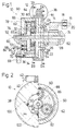
- the displacement sensor 10 is directly in the force path between an electrical one shown in simplified form in FIG. 1 Servomotor 12 and an output member arranged in the form of a rack 14.
- This rack is arranged directly with the part 16 to be adjusted, which for the sake of simplicity is symbolized as a cross bar in FIG. 1.
- a pre-tensioning device 20 (symbolized by a helical compression spring) arranged between a fixed counter bearing 18 and the part 16 to be adjusted prestresses the part 16 and thus the rack 14 in such a way that in all possible adjustment directions all gear parts between part 16 and servomotor 12 interlock under tension.
- the same contact surfaces, in particular tooth flanks, of successive parts are therefore always in contact with one another, so that any movement play between successive gear parts does not affect the displacement measurement of the displacement sensor 10.
- the displacement sensor 10 comprises a drive member 22 which can be driven by the servomotor 12 and which in turn drives an intermediate member 26 via an overload clutch 24.
- This pontic has several functions. On the one hand, it drives the rack 14 directly via a pinion section 28. On the other hand, it drives a reduction gear in the form of a planetary gear 30, specifically via a sun gear section 32.
- the planetary gear 30 serves to reduce the rotary movement of the intermediate member 26 in such a way that a planet gear carrier 34 of the planetary gear 30 rotates a little less than 360 ° during the full displacement path of the rack 14.
- the planet gear carrier 34 is part of a rotary potentiometer 36.
- the tapped potentiometer voltage U can therefore always be clearly assigned to the respective rack position.
- the overload clutch 24 prevents damage to parts of the actuator or the connected device to be adjusted by the actuator, for example a multi-speed derailleur.
- the overload clutch can be formed by a pure friction clutch, since a Changing the mutual rotational orientation of the coupling parts after an overload does not affect the accuracy of the distance measurement. This is because the position sensor 10 does not detect the rotational position of the drive motor 12, but rather the actual position of the rack 14 and thus of the part 16 to be adjusted.
- overload clutch 24 shown in the figures with releasable latching between the clutch parts, is preferably used, which is characterized by slip-free operation in the normal case, simple manufacture and a well-defined triggering torque.
- the hollow wheel-shaped drive member 22 is formed on its outer circumference with a worm gear toothing 38, in which a worm 42 mounted on a motor shaft 40 of the servomotor 12 engages in a rotationally fixed manner.
- the radially extending bottom 44 of the hollow wheel-shaped drive member 22 has a central circular opening 46 with several, for example semicircular, recesses 48. In the exemplary embodiment shown, four such recesses 48 are evenly distributed over the circumference of the circular opening 46. These locking recesses 48 serve for the partial accommodation of pin-shaped locking parts 50. These protrude in the direction parallel to all of the rotating elements of the displacement sensor 10 axis 52 from a radially extending circular disk 54 as part of the intermediate member 26.
- the locking parts are designed to be resilient and resilient transversely to their respective longitudinal direction.
- the latching parts 50 consequently pivot radially inward out of the latching recesses 48, so that the drive member 44 and the intermediate member 26 can be rotated relative to one another. With a corresponding further rotation or backward rotation of both parts, the latching parts 50 in turn snap into the latching recesses 48.
- the drive member 44 can be plugged directly onto the intermediate member 26 in the axial direction and then held by the intermediate member 26. This also results in a particularly compact design.
- the circular disk 54 of the intermediate member 26 is in the assembled state within the ring gear opening of the drive member 44, the outer circumference of the circular disk 54 can serve as a bearing surface for the inner circumference of the ring gear.
- Beveled locking heads provided on the outer ends of the locking parts serve to axially fix the drive member 44 to the intermediate member 26, possibly supported by a recess 58 adapted to the thickness of the bottom wall 44 of the drive part 22 on each locking part 50. Due to the radially outward slope of the Snap heads 48 can be easily plugged together.
- the planetary gear 30 serves to reduce the rotary movement of the intermediate member 26, in such a way that the planet carrier 34 rotates less than 360 ° during the entire stroke of the movement of the rack 14, so that each rotational position of the planet carrier 34 is uniquely assigned a specific rack position.
- the planet gear carrier 34 consists of a radially extending annular disc integral with the rest of the intermediate member 26, on the right side of which in FIG. 1 planet gears 60 (three in the exemplary embodiment shown) are rotatably mounted on axle journals 62. These planet gears engage on the one hand in the toothing of the already mentioned sun gear section 32 of the intermediate member 26 and on the other hand in an inner peripheral toothing 64 of a ring-shaped sensor housing 66 Fig. 1, is indicated at the bottom left.
- the sensor housing 66 is slightly different from the ring gear Drive member 24 overlapped, so that there is an axially short construction. This also contributes to the fact that the planet gear carrier 34 has a bearing collar 72 projecting to the left in FIG. 1, which is penetrated by a common bearing shaft 74 of the planet gear carrier 34 and the intermediate member 26 and which is in a correspondingly dimensioned central bearing bore 76 in the ring gear base 78 of the sensor housing 66 is inserted.
- the bearing collar 72 increases the inner bearing surface 80 while increasing the tilting rigidity; since it penetrates into the bottom wall 78, there is no increase in the axial length.
- the common bearing shaft 74 can be supported on one side or, better, on both sides, as indicated in FIG. 1 with broken shaft bearings 82.
- the planet gear carrier 34 forms a movable sensor part of a signal generator, generally designated 84.
- the signal transmitter supplies a signal U indicating the current rotational position of the planet gear carrier 34, from which the current position of the rack 14 can be derived directly.
- the signal generator 84 is designed with the rotary potentiometer 36 already mentioned, the associated sliding track 86 being arranged on the moving part (here planetary gear carrier 34) in the preferred exemplary embodiment shown and an associated sliding contact on the fixed sensor housing 66.
- the slideway 84 and a further reduced-diameter slideway 88 acted upon by one of the voltage sources with the output voltage U0 both run on the side of the circular-disk-shaped planet gear carrier 34 facing away from the planet gears 60, namely concentrically to the axis 52 defined by the common bearing shaft 74 1, indicated above by a connecting line 90, there is a conductive connection between the slideways 86 and 88 in an angular position.
- the sliding track 86 is connected to ground potential. Both connection points are preferably located directly next to one another with the grinding track 86 being separated between the two connection points. In this way, a variation of the tapped voltage U between ground potential and maximum voltage U0 is obtained with a nearly full 360 ° rotation (for example 270 °, better 350 °).
- the sliding contacts respectively assigned to the two sliding tracks 86 and 88 are designed in the exemplary embodiment shown as contact pins 92 which are spring-biased to bear against the sliding tracks (symbolized by compression springs 94 in FIG. 1) and each in a correspondingly graduated recess 96 in the bottom 78 of the bottom Sensor housing 66 are slidably guided parallel to the axis 52.
- the associated electrical connecting lines are each indicated in FIG. 1 with a dash-dot line and designated 98.
- FIG. 2 A possible embodiment of the idle stroke clutch is indicated in FIG. 2, left half and designated 100.
- the idle stroke is realized here in a driving recess 102, which is elongated in the circumferential direction and is indicated by dashed lines, on the inner circumference of the bottom 44 of the hollow-wheel-shaped drive member 22, in each of which one of the pin-shaped locking parts 50 with a circular cross section engages.
- Each of the pins 50 is assigned a corresponding arcuate recess 102, so that there is an idle stroke corresponding to the arc length (minus the diameter of the respective latching part 50).
- the idle stroke clutch 100 simultaneously serves as an overload clutch in both possible end positions, since, as described above, the pins 50 can deflect radially inward in the event of an overload.
- the arrangement described above has the advantage that a relatively inexpensive rotary potentiometer 36 can be used, which also together with the Pinion section 28 of the intermediate member 26 can be "trimmed", ie, in the assembled state, can be brought to a predetermined resistance profile by appropriate reworking of the sliding track 86. Also, the exact position of the rack 14 is always precisely recognized when decoupled by overload or idle stroke movement. Due to the described interlocking of the hollow wheel-shaped components, a compact design results. Due to the pretensioning with the aid of the pretensioning device 20, manufacturing inaccuracies, in particular movement play, between successive gear members do not have an effect on the signal of the signal generator 84. Finally, the absolute position of the rack 14 is also always determined, regardless of any intermittent power failure.
Landscapes
- Engineering & Computer Science (AREA)
- General Engineering & Computer Science (AREA)
- Mechanical Engineering (AREA)
- Chemical & Material Sciences (AREA)
- Combustion & Propulsion (AREA)
- Transportation (AREA)
- Transmission Devices (AREA)
- One-Way And Automatic Clutches, And Combinations Of Different Clutches (AREA)
Applications Claiming Priority (2)
| Application Number | Priority Date | Filing Date | Title |
|---|---|---|---|
| DE4134794A DE4134794A1 (de) | 1991-10-22 | 1991-10-22 | Weggeber fuer einen stellantrieb, insbesondere in einem fahrzeug |
| DE4134794 | 1991-10-22 |
Publications (2)
| Publication Number | Publication Date |
|---|---|
| EP0538802A1 true EP0538802A1 (fr) | 1993-04-28 |
| EP0538802B1 EP0538802B1 (fr) | 1995-06-28 |
Family
ID=6443143
Family Applications (1)
| Application Number | Title | Priority Date | Filing Date |
|---|---|---|---|
| EP92117941A Expired - Lifetime EP0538802B1 (fr) | 1991-10-22 | 1992-10-20 | Capteur de position pour un servomoteur, notamment pour un véhicule |
Country Status (3)
| Country | Link |
|---|---|
| US (1) | US5359884A (fr) |
| EP (1) | EP0538802B1 (fr) |
| DE (2) | DE4134794A1 (fr) |
Cited By (7)
| Publication number | Priority date | Publication date | Assignee | Title |
|---|---|---|---|---|
| FR2716430A1 (fr) * | 1994-02-24 | 1995-08-25 | Campagnolo Srl | Dispositif de changement de vitesse pour les bicyclettes. |
| EP0676518A3 (fr) * | 1994-03-08 | 1996-04-24 | Mivzarit High Tech Systems 199 | Ensemble de verrouillage activable par moteur électrique et/ou par clef mécanique. |
| FR2730073A1 (fr) * | 1995-02-01 | 1996-08-02 | Fichtel & Sachs Ag | Dispositif d'actionnement, notamment pour un vehicule, par exemple pour un embrayage de celui-ci |
| WO1996030230A3 (fr) * | 1995-03-31 | 1996-12-19 | United Technologies Automotive | Train d'engrenages pour regler le retroviseur d'un vehicule |
| EP0785323A1 (fr) * | 1996-01-16 | 1997-07-23 | Nissan European Technology Centre Limited | Système de verrouillage central pour porte de véhicule automobile |
| DE112004000398B4 (de) * | 2003-03-11 | 2017-04-06 | Valeo Embrayages | Kupplungsbetätigungsvorrichtung |
| EP3204578A4 (fr) * | 2014-10-08 | 2018-06-13 | Candy House Inc. | Ensemble engrenage et mécanisme de monture de porte comprenant celui-ci |
Families Citing this family (31)
| Publication number | Priority date | Publication date | Assignee | Title |
|---|---|---|---|---|
| JPH1120729A (ja) * | 1997-07-02 | 1999-01-26 | Toyota Autom Loom Works Ltd | 車両におけるセンサの取付構造 |
| EP0960994A3 (fr) * | 1998-05-26 | 2002-09-04 | Siemens Aktiengesellschaft | Dispositif de verrouillage, en particulier pour un véhicule |
| DE19839707C2 (de) * | 1998-09-01 | 2000-11-16 | Mannesmann Vdo Ag | Schließeinrichtung, insbesondere für Fahrzeuge |
| US6162140A (en) * | 1998-12-18 | 2000-12-19 | Shimano, Inc. | Motor driven derailleur |
| IT1310731B1 (it) * | 1999-11-23 | 2002-02-22 | Campagnolo Srl | Dispositivo di cambio di velocita' per biciclette. |
| US6244415B1 (en) * | 1999-12-30 | 2001-06-12 | Shimano, Inc. | Motor controlled shift control device including an idler gear for a bicycle transmission |
| JP2003522924A (ja) * | 2000-02-15 | 2003-07-29 | ルーク ラメレン ウント クツプルングスバウ ベタイリグングス コマンディートゲゼルシャフト | 自動化されたシフト型トランスミッションのアクチュエータの操作位置を検出する方法 |
| FR2813935B1 (fr) * | 2000-09-08 | 2002-11-29 | Renault | Boite de vitesses a actionneur de passage |
| JP4845255B2 (ja) * | 2000-10-17 | 2011-12-28 | 株式会社ハーモニック・ドライブ・システムズ | アブソリュートセンサ |
| DE10118663A1 (de) * | 2001-04-14 | 2002-10-17 | Zf Lenksysteme Gmbh | Betätigungseinrichtung für ein Fahrzeug-Lenkeinrichtung |
| FR2824581B1 (fr) * | 2001-05-10 | 2006-01-13 | Valeo Securite Habitacle | Dispositif d'actionnement en rotation d'un organe a actionner de vehicule automobile |
| FR2830594B1 (fr) * | 2001-10-10 | 2004-08-27 | Giat Ind Sa | Dispositif d'asservissement d'une charge a precontrainte variable |
| KR20040097124A (ko) * | 2002-02-08 | 2004-11-17 | 로베르트 보쉬 게엠베하 | 광학 토크 및 각 센서 |
| US6732438B2 (en) * | 2002-04-02 | 2004-05-11 | Delphi Technologies, Inc. | Rotary position sensor |
| USD557653S1 (en) | 2002-11-15 | 2007-12-18 | Campagnolo Srl | Bottle cage |
| US6945888B2 (en) * | 2002-11-21 | 2005-09-20 | Shimano, Inc. | Combined analog and digital derailleur position processing apparatus |
| US6997835B2 (en) * | 2002-11-26 | 2006-02-14 | Shimano, Inc. | Electrically operated derailleur with power storing mechanism |
| FR2875250B1 (fr) * | 2004-09-10 | 2008-11-21 | Laperche Sa | Module d'entrainement d'une serrure et ensemble correspondant |
| JP2007203954A (ja) * | 2006-02-03 | 2007-08-16 | Shimano Inc | 自転車用ディレーラ |
| EP1879087A3 (fr) * | 2006-07-10 | 2010-08-18 | Brose Schliesssysteme GmbH & Co. KG | Dispositif de détection de position pour un élément fonctionnel déplaçable et motorisé dans un véhicule |
| US8066597B2 (en) * | 2007-03-15 | 2011-11-29 | Shimano, Inc. | Electrically operated derailleur with force overload protection |
| US7942768B2 (en) * | 2008-01-28 | 2011-05-17 | Shimano, Inc. | Electrically operated derailleur that re-engages a disengaged derailleur force overload clutch |
| US7892122B2 (en) * | 2008-02-22 | 2011-02-22 | Shimano, Inc. | Electrically operated derailleur with a power storing mechanism |
| JP5185677B2 (ja) * | 2008-03-31 | 2013-04-17 | 三菱重工業株式会社 | 自動調芯嵌合クラッチを用いた駆動力伝達機構における軸ズレ量検知方法 |
| DE102012013934A1 (de) * | 2012-07-16 | 2014-01-16 | Krohne Ag | Verfahren zum Betreiben einer Einstellvorrichtung |
| US12508928B2 (en) * | 2019-10-17 | 2025-12-30 | Schunk Transit Systems Gmbh | Positioning unit for a charging station, and method for making contact |
| WO2022068481A1 (fr) * | 2020-09-30 | 2022-04-07 | 深圳市凯迪仕智能科技有限公司 | Mécanisme d'entraînement destiné à une serrure de porte, et serrure de porte |
| WO2022127179A1 (fr) * | 2020-12-14 | 2022-06-23 | 深圳市凯迪仕智能科技有限公司 | Corps de verrou électrique |
| CN113027238B (zh) * | 2021-03-12 | 2022-05-17 | 海信集团控股股份有限公司 | 一种启动防猫眼开锁功能的方法及其智能门锁 |
| DE102021206654A1 (de) | 2021-06-28 | 2022-12-29 | Zf Friedrichshafen Ag | Betätigungsvorrichtung für die Betätigung eines Stellelements einer Stelleinrichtung eines Kraftfahrzeugs |
| US12275491B2 (en) * | 2023-08-28 | 2025-04-15 | Shimano Inc. | Bicycle motor unit and bicycle derailleur |
Citations (6)
| Publication number | Priority date | Publication date | Assignee | Title |
|---|---|---|---|---|
| FR2247376A1 (fr) * | 1973-10-15 | 1975-05-09 | Stuhlmuller Brian | |
| GB2157387A (en) * | 1984-04-11 | 1985-10-23 | Iku Holding Montfoort Bv | Rotary position indicating device in overload slip system for adjusting mirrors |
| US4573723A (en) * | 1983-11-26 | 1986-03-04 | Nippondenso Co., Ltd. | System including bi-directional drive mechanism |
| WO1988001962A2 (fr) * | 1986-09-16 | 1988-03-24 | Villiger Söhne Ag | Changement de vitesse electromecanique pour bicyclette |
| EP0267423A2 (fr) * | 1986-10-06 | 1988-05-18 | Aisin Seiki Kabushiki Kaisha | Serrure pour porte de véhicule automobile |
| DE3703392A1 (de) * | 1987-02-05 | 1988-08-18 | Fichtel & Sachs Ag | Elektrische zentral-verriegelungs-einrichtung fuer tueren, hauben und/oder deckel insbesondere an kraftfahrzeugen |
Family Cites Families (9)
| Publication number | Priority date | Publication date | Assignee | Title |
|---|---|---|---|---|
| US3764162A (en) * | 1971-12-21 | 1973-10-09 | Raymond Lee Organization Inc | Automatic landing gear device |
| US4556116A (en) * | 1984-08-30 | 1985-12-03 | Eaton Corporation | Fail-safe mechanism for an electrical power assisted steering system |
| JPS6158169U (fr) * | 1984-09-21 | 1986-04-18 | ||
| DE3527546C1 (de) * | 1985-08-01 | 1986-10-02 | Dr. Johannes Heidenhain Gmbh, 8225 Traunreut | Vorrichtung zum Verbinden einer Positionsmesseinrichtung mit zwei relativ zueinander beweglichen Objekten |
| JPS638071A (ja) * | 1986-06-25 | 1988-01-13 | Hitachi Ltd | 電動式パワ−ステアリング装置 |
| US4809656A (en) * | 1987-04-14 | 1989-03-07 | Nippon Cable System Inc. | Actuator for automatic cruising system |
| DE3728601C1 (de) * | 1987-08-27 | 1988-09-29 | Daimler Benz Ag | Zentralverriegelungsanlage fuer Tuer- und Deckelverschluesse eines Kraftfahrzeugs |
| JPH03122978U (fr) * | 1990-03-28 | 1991-12-13 | ||
| JPH04224241A (ja) * | 1990-12-26 | 1992-08-13 | Aisin Seiki Co Ltd | スロットル制御装置 |
-
1991
- 1991-10-22 DE DE4134794A patent/DE4134794A1/de not_active Withdrawn
-
1992
- 1992-10-15 US US07/962,327 patent/US5359884A/en not_active Expired - Fee Related
- 1992-10-20 DE DE59202708T patent/DE59202708D1/de not_active Expired - Fee Related
- 1992-10-20 EP EP92117941A patent/EP0538802B1/fr not_active Expired - Lifetime
Patent Citations (6)
| Publication number | Priority date | Publication date | Assignee | Title |
|---|---|---|---|---|
| FR2247376A1 (fr) * | 1973-10-15 | 1975-05-09 | Stuhlmuller Brian | |
| US4573723A (en) * | 1983-11-26 | 1986-03-04 | Nippondenso Co., Ltd. | System including bi-directional drive mechanism |
| GB2157387A (en) * | 1984-04-11 | 1985-10-23 | Iku Holding Montfoort Bv | Rotary position indicating device in overload slip system for adjusting mirrors |
| WO1988001962A2 (fr) * | 1986-09-16 | 1988-03-24 | Villiger Söhne Ag | Changement de vitesse electromecanique pour bicyclette |
| EP0267423A2 (fr) * | 1986-10-06 | 1988-05-18 | Aisin Seiki Kabushiki Kaisha | Serrure pour porte de véhicule automobile |
| DE3703392A1 (de) * | 1987-02-05 | 1988-08-18 | Fichtel & Sachs Ag | Elektrische zentral-verriegelungs-einrichtung fuer tueren, hauben und/oder deckel insbesondere an kraftfahrzeugen |
Cited By (9)
| Publication number | Priority date | Publication date | Assignee | Title |
|---|---|---|---|---|
| FR2716430A1 (fr) * | 1994-02-24 | 1995-08-25 | Campagnolo Srl | Dispositif de changement de vitesse pour les bicyclettes. |
| EP0676518A3 (fr) * | 1994-03-08 | 1996-04-24 | Mivzarit High Tech Systems 199 | Ensemble de verrouillage activable par moteur électrique et/ou par clef mécanique. |
| FR2730073A1 (fr) * | 1995-02-01 | 1996-08-02 | Fichtel & Sachs Ag | Dispositif d'actionnement, notamment pour un vehicule, par exemple pour un embrayage de celui-ci |
| DE19503137C1 (de) * | 1995-02-01 | 1996-09-26 | Fichtel & Sachs Ag | Betätigungsvorrichtung, insbesondere für ein Fahrzeug |
| US5678671A (en) * | 1995-02-01 | 1997-10-21 | Fichtel & Sachs Ag | Motor vehicle clutch assembly having an actuator device, which actuator device has a clutch motion blocking system |
| WO1996030230A3 (fr) * | 1995-03-31 | 1996-12-19 | United Technologies Automotive | Train d'engrenages pour regler le retroviseur d'un vehicule |
| EP0785323A1 (fr) * | 1996-01-16 | 1997-07-23 | Nissan European Technology Centre Limited | Système de verrouillage central pour porte de véhicule automobile |
| DE112004000398B4 (de) * | 2003-03-11 | 2017-04-06 | Valeo Embrayages | Kupplungsbetätigungsvorrichtung |
| EP3204578A4 (fr) * | 2014-10-08 | 2018-06-13 | Candy House Inc. | Ensemble engrenage et mécanisme de monture de porte comprenant celui-ci |
Also Published As
| Publication number | Publication date |
|---|---|
| DE4134794A1 (de) | 1993-04-29 |
| US5359884A (en) | 1994-11-01 |
| DE59202708D1 (de) | 1995-08-03 |
| EP0538802B1 (fr) | 1995-06-28 |
Similar Documents
| Publication | Publication Date | Title |
|---|---|---|
| EP0538802B1 (fr) | Capteur de position pour un servomoteur, notamment pour un véhicule | |
| EP4095017B1 (fr) | Actionneur de direction pour système de direction et système de direction pour véhicule automobile | |
| EP0699151B1 (fr) | Detecteur pour la determination de l'angle de braquage | |
| EP1425523B1 (fr) | Boite de vitesses a actionneur electromecanique | |
| EP0211195B1 (fr) | Dispositif d'accouplement | |
| EP0469286B1 (fr) | Dispositif d'entraînement pour parties mobiles d'un véhicule automobile | |
| DE102011005370B4 (de) | Hebelbetätigungsvorrichtung | |
| DE102019103384A1 (de) | Planetenwälzgewindetrieb | |
| EP2246668A1 (fr) | Mécanisme de commande électrique | |
| DE102008033236A1 (de) | Lenkwinkelsensor, insbesondere für ein Kraftfahrzeug | |
| WO2021121855A1 (fr) | Dispositif actionneur servant à générer un mouvement de positionnement longitudinal | |
| EP0460378B1 (fr) | Dispositif de commande de frein à dispositif pour ajuster un frein | |
| DE20018564U1 (de) | Betätigungsvorrichtung | |
| DE102019125310A1 (de) | Planetenwälzgetriebe | |
| DE69718526T2 (de) | Vorrichtung zur Ermittlung der Position eines sich bewegenden Körpers | |
| DE69321832T2 (de) | Zahnradpaar und Steuerkolonne-Schalter mit einem solchen Paar | |
| DE19702833C2 (de) | Positionssensor zum Erfassen einer bestimmten Bewegungsposition eines in einer Vorwärtsrichtung und einer Rückwärtsrichtung bewegbaren Körpers | |
| EP1312534A2 (fr) | Dispositif pour la détermination de l'angle de braquage d'un volant | |
| DE10004707C2 (de) | Selbstverstellende Schrauberanordnung | |
| EP2947353B1 (fr) | Essieu-moteur de véhicule | |
| DE102023120475B4 (de) | Antriebsvorrichtung für einen Roboter sowie Roboter mit einer solchen Antriebsvorrichtung | |
| EP3064793A1 (fr) | Système de capteur de mouvement pour véhicules sur rail | |
| DE102011005372A1 (de) | Hebelbetätigungsvorrichtung | |
| EP0707541B1 (fr) | Systeme d'entrainement pour une partie reglable d'un vehicule | |
| DE102024113690A1 (de) | Abgreifeinrichtung für eine Lenkwinkelerfassungseinrichtung für eine Schubstange eines Lenkgetriebes eines Fahrzeugs, Lenkwinkelerfassungsein-richtung, Lenkgetriebe und Fahrzeug |
Legal Events
| Date | Code | Title | Description |
|---|---|---|---|
| PUAI | Public reference made under article 153(3) epc to a published international application that has entered the european phase |
Free format text: ORIGINAL CODE: 0009012 |
|
| AK | Designated contracting states |
Kind code of ref document: A1 Designated state(s): DE FR GB IT SE |
|
| 17P | Request for examination filed |
Effective date: 19930517 |
|
| 17Q | First examination report despatched |
Effective date: 19940701 |
|
| GRAA | (expected) grant |
Free format text: ORIGINAL CODE: 0009210 |
|
| AK | Designated contracting states |
Kind code of ref document: B1 Designated state(s): DE FR GB IT SE |
|
| ITF | It: translation for a ep patent filed | ||
| GBT | Gb: translation of ep patent filed (gb section 77(6)(a)/1977) |
Effective date: 19950630 |
|
| REF | Corresponds to: |
Ref document number: 59202708 Country of ref document: DE Date of ref document: 19950803 |
|
| ET | Fr: translation filed | ||
| PLBE | No opposition filed within time limit |
Free format text: ORIGINAL CODE: 0009261 |
|
| STAA | Information on the status of an ep patent application or granted ep patent |
Free format text: STATUS: NO OPPOSITION FILED WITHIN TIME LIMIT |
|
| 26N | No opposition filed | ||
| REG | Reference to a national code |
Ref country code: GB Ref legal event code: 732E |
|
| REG | Reference to a national code |
Ref country code: FR Ref legal event code: TP Ref country code: FR Ref legal event code: CD |
|
| PGFP | Annual fee paid to national office [announced via postgrant information from national office to epo] |
Ref country code: GB Payment date: 20000915 Year of fee payment: 9 |
|
| PGFP | Annual fee paid to national office [announced via postgrant information from national office to epo] |
Ref country code: SE Payment date: 20001002 Year of fee payment: 9 |
|
| PGFP | Annual fee paid to national office [announced via postgrant information from national office to epo] |
Ref country code: FR Payment date: 20001012 Year of fee payment: 9 |
|
| PG25 | Lapsed in a contracting state [announced via postgrant information from national office to epo] |
Ref country code: GB Free format text: LAPSE BECAUSE OF NON-PAYMENT OF DUE FEES Effective date: 20011020 |
|
| PG25 | Lapsed in a contracting state [announced via postgrant information from national office to epo] |
Ref country code: SE Free format text: LAPSE BECAUSE OF NON-PAYMENT OF DUE FEES Effective date: 20011021 |
|
| REG | Reference to a national code |
Ref country code: GB Ref legal event code: IF02 |
|
| EUG | Se: european patent has lapsed |
Ref document number: 92117941.2 |
|
| GBPC | Gb: european patent ceased through non-payment of renewal fee |
Effective date: 20011020 |
|
| PG25 | Lapsed in a contracting state [announced via postgrant information from national office to epo] |
Ref country code: FR Free format text: LAPSE BECAUSE OF NON-PAYMENT OF DUE FEES Effective date: 20020628 |
|
| REG | Reference to a national code |
Ref country code: FR Ref legal event code: ST |
|
| PG25 | Lapsed in a contracting state [announced via postgrant information from national office to epo] |
Ref country code: IT Free format text: LAPSE BECAUSE OF NON-PAYMENT OF DUE FEES;WARNING: LAPSES OF ITALIAN PATENTS WITH EFFECTIVE DATE BEFORE 2007 MAY HAVE OCCURRED AT ANY TIME BEFORE 2007. THE CORRECT EFFECTIVE DATE MAY BE DIFFERENT FROM THE ONE RECORDED. Effective date: 20051020 |
|
| PGFP | Annual fee paid to national office [announced via postgrant information from national office to epo] |
Ref country code: DE Payment date: 20081031 Year of fee payment: 17 |
|
| PG25 | Lapsed in a contracting state [announced via postgrant information from national office to epo] |
Ref country code: DE Free format text: LAPSE BECAUSE OF NON-PAYMENT OF DUE FEES Effective date: 20100501 |