EP0539150A2 - Infrarot-Detektor - Google Patents
Infrarot-Detektor Download PDFInfo
- Publication number
- EP0539150A2 EP0539150A2 EP92309561A EP92309561A EP0539150A2 EP 0539150 A2 EP0539150 A2 EP 0539150A2 EP 92309561 A EP92309561 A EP 92309561A EP 92309561 A EP92309561 A EP 92309561A EP 0539150 A2 EP0539150 A2 EP 0539150A2
- Authority
- EP
- European Patent Office
- Prior art keywords
- chopper
- amplifier
- detector
- gain
- control circuit
- Prior art date
- Legal status (The legal status is an assumption and is not a legal conclusion. Google has not performed a legal analysis and makes no representation as to the accuracy of the status listed.)
- Granted
Links
Images


Classifications
-
- G—PHYSICS
- G08—SIGNALLING
- G08B—SIGNALLING SYSTEMS, e.g. PERSONAL CALLING SYSTEMS; ORDER TELEGRAPHS; ALARM SYSTEMS
- G08B13/00—Burglar, theft or intruder alarms
- G08B13/18—Actuation by interference with heat, light, or radiation of shorter wavelength; Actuation by intruding sources of heat, light, or radiation of shorter wavelength
- G08B13/189—Actuation by interference with heat, light, or radiation of shorter wavelength; Actuation by intruding sources of heat, light, or radiation of shorter wavelength using passive radiation detection systems
- G08B13/19—Actuation by interference with heat, light, or radiation of shorter wavelength; Actuation by intruding sources of heat, light, or radiation of shorter wavelength using passive radiation detection systems using infrared-radiation detection systems
- G08B13/191—Actuation by interference with heat, light, or radiation of shorter wavelength; Actuation by intruding sources of heat, light, or radiation of shorter wavelength using passive radiation detection systems using infrared-radiation detection systems using pyroelectric sensor means
Definitions
- This invention relates to an infrared detector, and more particularly to an IR (infrared) detector which enables both detection of a moving person and detection of radiation temperature by using a single pyroelectric infrared detector element.
- a pyroelectric infrared detector element is a thermal type of infrared detector element having the differential type of output characteristics, which has been used for various applications because of its features such as high sensitivity, availability under room temperature, and low cost.
- the representative applications include a detector for moving person and a detector for radiation temperature of a disaster preventing equipment and other industrial equipment.
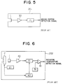
- FIG.5 of the accompanying drawings shows an example of a conventional moving person detector.
- This moving person detector 201 comprises a pyroelectric infrared detector element 1.
- an AC amplifier 30 which amplifies output from the pyroelectric infrared detector element 1 in AC mode
- a comparator 71 which compares output from the AC amplifier 30 to the prespecified reference value, and outputs a moving person detection signal when a person comes into a field of view of the pyroelectric infrared detector element 1.
- the target for detection is only a change caused by movement of a person within the total infrared ray energy input to the pyroelectric infrared detector element 1. This change level is very weak, and accordingly a gain (amplification factor) of the AC amplifier 30 is required around 70 dB.
- FIG. 6 of the drawings shows an example of a conventional radiation temperature detector.
- This radiation temperature detector 202 comprises the pyroelectric infrared detector element 1, a chopper mechanism 2 for cyclically interrupting the infrared ray input to the pyroelectric infrared detector element 1, a chopper driving circuit 21 which drives the chopper mechanism 2, an AC amplifier 40 which amplifies output from the pyroelectric infrared detector element 1 in AC mode, a sample/hold circuit 41 for synchronous detecting an output signal from the AC amplifier 40, a sampling signal generating circuit 42 which generates a sampling signal synchronized to the output signal from the chopper driving circuit 21 and gives the sampling signal to the sample/hold circuit 41, a temperature compensator 51 which generates a temperature compensating signal based on the temperature information detected by a temperature detecting element (not shown) provided adjacent to the chopper mechanism 2, and a DC amplifier 61 which generates a radiation temperature detection signal which is proportional to the infrared ray energy input to the pyroelectric infrared detector element 1; and outputs a radiation temperature detection signal
- the target for detection is the total infrared ray energy input to the pyroelectric infrared detector element 1. This is enabled by cyclically interrupting the infrared ray energy input to the pyroelectric infrared detector element 1 with the chopper mechanism 2. A level of this total infrared ray energy is relatively high, and the gain of the AC amplifier 40 is in a range from 30 to 40 dB.
- An object of the invention is to provide an IR detector which enables both detection of moving person and detection of radiation temperature.
- the IR detector according to the invention has a pyroelectric infrared detector element, a chopper mechanism which cyclically interrupts an infrared ray input to the pyroelectric infrared detector element, a chopper driving circuit which drives the chopper mechanism, and an AC amplifier which amplifies an output signal from the pyroelectric infrared detector element in AC mode; and is characterized in that said IR detector includes a chopper control circuit which controls start/stop of the chopper mechanism according to a control signal input from outside and a gain control circuit which changes the gain of the AC amplifier.
- the chopper control circuit stops operation of the chopper mechanism. So, the pyroelectric infrared detector element outputs only a changed factor caused by movement of a person within the input infrared ray energy.
- the gain control circuit changes the gain of the AC amplifier so that an optimal value for amplification of the output will be provided. Thus, a function as a moving person detector is provided by this operation.
- the input infrared ray is cyclically interrupted by the chopper mechanism. So, the pyroelectric infrared detector element outputs a total of the input infrared ray energy.
- the gain control circuit changes the gain of the AC amplifier so that an optimal value for amplification of the output will be obtained.
- a function as a radiation temperature detector is provided by this operation.
- FIG. 1 shows a block diagram of an IR detector 101 according to an embodiment of the invention.
- This IR detector 101 comprises a pyroelectric infrared detector element 1, a chopper mechanism 2, a chopper driving mechanism 21, a chopper control circuit 22 which controls operation of the chopper driving circuit 21, an AC amplifier 31 which amplifies output from the pyroelectric infrared detector element 1, a comparator 71, a gain control circuit 32 which changes a gain of the AC amplifier 31 according to output from the chopper control circuit 22, a sample/hold circuit 41, a sampling signal generating circuit 42, a temperature compensator 51, and a DC amplifier 61.
- the chopper control circuit 22 starts operation of the chopper mechanism 21 if a control signal input to an input terminal 85 is "L”, and stops operation of the chopper mechanism 21 in the open state if the control signal is "H".
- FIG. 2 shows an example of the chopper control circuit 22.
- the chopper control circuit 22 comprises an operational amplifier U1, transistors Tr1 and Tr2, a capacitor Ct, a resistor Rt, and resistors R1 through R5.
- Tr1 turns on and stops charging of Ct. With this, oscillation is stopped and the oscillation output is not fed to the chopper driving circuit 21. For this reason, operation of the chopper driving circuit 21 is stopped, and the chopper mechanism 2, to which a bias force is given so that it is turned to an open state, is stopped in the open state.
- the gain control circuit 32 reduces a gain of the AC amplifier 31 if the control signal input to a control input terminal 85 is "L”, and increases the gain of the AC amplifier 31 if the control signal is "H".
- FIG. 3 shows examples of the AC amplifier 31 and the gain control circuit 32.
- a gain within a frequency band is decided by the Rs, Cs, Rf, Cf, R6, and R7.
- a transistor Tr3 is used as a bipolar switch.
- the control signal is "L" until time t1, and the chopper mechanism 2 cyclically repeats the open state and the closed state.
- the operation frequency is, for instance, 1.5 Hz.
- Output from the pyroelectric infrared detector element 1 is the one corresponding to a total of the input infrared ray energy.
- the gain of the AC amplifier 31 is forcefully decreased to, for instance, 38 dB, because the control signal is "L".
- So output from the AC amplifier 31 is obtained by amplifying output from the pyroelectric infrared detector element 1 with, for instance, 38 dB.
- the sampling signal is a pulse with a width tw (for instance, 12 ms ) at a timing of delayed time td (for instance, 200 ms ) from switching from the open state to the closed state of the chopper mechanism 2.
- output from the sample/hold circuit 41 is an output value from the AC amplifier 31 when the sampling signal is input.
- a radiation temperature detection signal (namely, output from the DC amplifier 61) is a value obtained by compensating the output value from the sample/hold circuit 41 according to the temperature. This value is proportional to an average temperature of an object which exists in a field of view of the pyroelectric infrared detector element 1.
- a moving person detection signal (namely, output from the comparator 71) is not generated, because the gain of the AC amplifier 31 has been reduced and output from the AC amplifier 31 does not exceed the reference value Vth.
- control signal is "H"
- the chopper mechanism 2 is kept open state.
- Output from the pyroelectric infrared detector element 1 is one which corresponds to a change of the input infrared ray.
- control signal is "H"
- the gain of the AC amplifier 31 has been raised to, for instance, 73 dB.
- output from the AC amplifier 31 is obtained by amplifying output from the pyroelectric infrared detector element 1 with, for instance, 73 dB.
- the sampling signal is not provided.
- the radiation temperature detection signal (namely, output from the DC amplifier 61) is a value obtained by compensating the output value from the sample/hold circuit 41 according to the temperature, but this value is meaningless herein.
- a moving person detection signal (namely, output from the comparator 71) becomes a detection signalof moving human body, because the gain of the AC amplifier 31 has been raised and output from the AC amplifier provided when a person moves exceeds the reference value Vth.
- the IR detector element 101 As described above, it is possible to detect both movement of a person and radiation temperature by using a single unit of the pyroelectric infrared detector element 1. Thus, it is possible to realize a small size and low cost IR detector.
- the chopper control circuit 22 may be replaced one which comprises digital IC invertors and gates.
- gain control circuit 32 may be replaced one which changes the Rf value in FIG. 3.
- detection of a moving person and detection of radiation temperature may be carried out by means of A/D conversion of output from the AC amplifier 31 and processing by a microcomputer.
- a moving person detector and a radiation temperature detector can be unified in a single unit. Also minimization of a detector and cost reduction are possible.
Landscapes
- Physics & Mathematics (AREA)
- General Physics & Mathematics (AREA)
- Photometry And Measurement Of Optical Pulse Characteristics (AREA)
- Radiation Pyrometers (AREA)
- Geophysics And Detection Of Objects (AREA)
Applications Claiming Priority (2)
| Application Number | Priority Date | Filing Date | Title |
|---|---|---|---|
| JP27284091A JP2682302B2 (ja) | 1991-10-21 | 1991-10-21 | 赤外線検出装置 |
| JP272840/91 | 1991-10-21 |
Publications (3)
| Publication Number | Publication Date |
|---|---|
| EP0539150A2 true EP0539150A2 (de) | 1993-04-28 |
| EP0539150A3 EP0539150A3 (en) | 1994-11-09 |
| EP0539150B1 EP0539150B1 (de) | 1998-12-30 |
Family
ID=17519509
Family Applications (1)
| Application Number | Title | Priority Date | Filing Date |
|---|---|---|---|
| EP92309561A Expired - Lifetime EP0539150B1 (de) | 1991-10-21 | 1992-10-20 | Infrarot-Detektor |
Country Status (4)
| Country | Link |
|---|---|
| US (1) | US5262647A (de) |
| EP (1) | EP0539150B1 (de) |
| JP (1) | JP2682302B2 (de) |
| DE (1) | DE69228041T2 (de) |
Cited By (2)
| Publication number | Priority date | Publication date | Assignee | Title |
|---|---|---|---|---|
| EP0886132A3 (de) * | 1997-06-22 | 1999-01-20 | Optrotherm Mess- und Sensortechnik GmbH | Verfahren und Vorrichtung zur digitalen Erfassung der Messdaten von Strahlungsdetektoren |
| CN106932093A (zh) * | 2017-02-21 | 2017-07-07 | 上海理工大学 | 自动锁频光电等效平衡系统 |
Families Citing this family (7)
| Publication number | Priority date | Publication date | Assignee | Title |
|---|---|---|---|---|
| JP2677127B2 (ja) * | 1992-09-17 | 1997-11-17 | 松下電器産業株式会社 | 熱画像検出装置 |
| FR2700091B1 (fr) * | 1992-12-30 | 1995-01-27 | Thomson Csf Semiconducteurs | Détecteur d'image thermique avec période d'obturation rapide et procédé de fonctionnement. |
| US5474085A (en) * | 1994-02-24 | 1995-12-12 | University Of Prince Edward Island | Remote thermographic sensing of livestock |
| US6245956B1 (en) * | 1995-02-14 | 2001-06-12 | Phillips Petroleum Company | Method for separating sulfone from a hydrocarbon stream having a small concentration of sulfone |
| US5772326A (en) * | 1996-08-30 | 1998-06-30 | Hubbell Incorporated | Temperature and passive infrared sensor module |
| US6340816B1 (en) | 1998-02-27 | 2002-01-22 | Honeywell International, Inc. | Pyroelectric detector with feedback amplifier for enhanced low frequency response |
| JP2000002733A (ja) * | 1998-06-15 | 2000-01-07 | Murata Mfg Co Ltd | 電位センサ |
Family Cites Families (4)
| Publication number | Priority date | Publication date | Assignee | Title |
|---|---|---|---|---|
| JPS62157538A (ja) * | 1985-12-31 | 1987-07-13 | Tdk Corp | 温度センサ |
| US4825075A (en) * | 1987-07-30 | 1989-04-25 | Lutron Electronics Co., Inc. | Non-electronic gain control |
| JPH01124721A (ja) * | 1987-11-09 | 1989-05-17 | Nippon Ceramic Kk | 赤外線検出装置 |
| JP2689644B2 (ja) * | 1989-09-21 | 1997-12-10 | 松下電器産業株式会社 | 焦電型赤外線検知装置 |
-
1991
- 1991-10-21 JP JP27284091A patent/JP2682302B2/ja not_active Expired - Fee Related
-
1992
- 1992-10-16 US US07/962,439 patent/US5262647A/en not_active Expired - Lifetime
- 1992-10-20 EP EP92309561A patent/EP0539150B1/de not_active Expired - Lifetime
- 1992-10-20 DE DE69228041T patent/DE69228041T2/de not_active Expired - Fee Related
Cited By (2)
| Publication number | Priority date | Publication date | Assignee | Title |
|---|---|---|---|---|
| EP0886132A3 (de) * | 1997-06-22 | 1999-01-20 | Optrotherm Mess- und Sensortechnik GmbH | Verfahren und Vorrichtung zur digitalen Erfassung der Messdaten von Strahlungsdetektoren |
| CN106932093A (zh) * | 2017-02-21 | 2017-07-07 | 上海理工大学 | 自动锁频光电等效平衡系统 |
Also Published As
| Publication number | Publication date |
|---|---|
| US5262647A (en) | 1993-11-16 |
| EP0539150B1 (de) | 1998-12-30 |
| EP0539150A3 (en) | 1994-11-09 |
| DE69228041T2 (de) | 1999-06-24 |
| JPH05113368A (ja) | 1993-05-07 |
| DE69228041D1 (de) | 1999-02-11 |
| JP2682302B2 (ja) | 1997-11-26 |
Similar Documents
| Publication | Publication Date | Title |
|---|---|---|
| US5627710A (en) | Electric motor drive system | |
| EP0539150B1 (de) | Infrarot-Detektor | |
| KR870001301B1 (ko) | 조리기의 온도 검도장치 | |
| US4760490A (en) | Proximity switch device | |
| US6677589B2 (en) | Object detecting device with a pyroelectric sensor | |
| EP0484445A4 (en) | Electrical switching system | |
| US5361023A (en) | Movable robot | |
| EP0939311A2 (de) | Infrarot-Strahlungsdetektor | |
| EP0588644A1 (de) | Wärmebilddetektionssystem | |
| EP0307911B1 (de) | Signaldiskriminator | |
| JP4460516B2 (ja) | 人体検知装置 | |
| US4942315A (en) | Base point floating cut off wave form differential signal detector circuit | |
| JP3059498B2 (ja) | 在室検出装置 | |
| JP3111878B2 (ja) | 煙感知器用led電流制御回路 | |
| KR820002115Y1 (ko) | 초단파 경보장치 | |
| KR960007980B1 (ko) | 공조기의 인체위치 감지장치 및 그 제어방법 | |
| KR900002480Y1 (ko) | 자동 감지 회로 | |
| JPH0445119B2 (de) | ||
| JPH1049094A (ja) | 表示装置 | |
| JPH0486590A (ja) | 監視装置 | |
| JPH0579909A (ja) | 熱線式検知器 | |
| KR960003993Y1 (ko) | 무선전화기의 잡음세력 감지회로 | |
| KR860003185Y1 (ko) | 센서에 의한 자동 제어회로 | |
| JP2000162324A (ja) | 赤外線検出装置 | |
| KR950010670A (ko) | 전자 시스템의 자동조작장치 및 그 조작방법 |
Legal Events
| Date | Code | Title | Description |
|---|---|---|---|
| PUAI | Public reference made under article 153(3) epc to a published international application that has entered the european phase |
Free format text: ORIGINAL CODE: 0009012 |
|
| AK | Designated contracting states |
Kind code of ref document: A2 Designated state(s): DE GB NL |
|
| PUAL | Search report despatched |
Free format text: ORIGINAL CODE: 0009013 |
|
| AK | Designated contracting states |
Kind code of ref document: A3 Designated state(s): DE GB NL |
|
| 17P | Request for examination filed |
Effective date: 19941219 |
|
| 17Q | First examination report despatched |
Effective date: 19970226 |
|
| GRAG | Despatch of communication of intention to grant |
Free format text: ORIGINAL CODE: EPIDOS AGRA |
|
| GRAG | Despatch of communication of intention to grant |
Free format text: ORIGINAL CODE: EPIDOS AGRA |
|
| GRAG | Despatch of communication of intention to grant |
Free format text: ORIGINAL CODE: EPIDOS AGRA |
|
| GRAH | Despatch of communication of intention to grant a patent |
Free format text: ORIGINAL CODE: EPIDOS IGRA |
|
| GRAH | Despatch of communication of intention to grant a patent |
Free format text: ORIGINAL CODE: EPIDOS IGRA |
|
| GRAA | (expected) grant |
Free format text: ORIGINAL CODE: 0009210 |
|
| AK | Designated contracting states |
Kind code of ref document: B1 Designated state(s): DE GB NL |
|
| REF | Corresponds to: |
Ref document number: 69228041 Country of ref document: DE Date of ref document: 19990211 |
|
| PLBE | No opposition filed within time limit |
Free format text: ORIGINAL CODE: 0009261 |
|
| 26N | No opposition filed | ||
| REG | Reference to a national code |
Ref country code: GB Ref legal event code: IF02 |
|
| PGFP | Annual fee paid to national office [announced via postgrant information from national office to epo] |
Ref country code: NL Payment date: 20051003 Year of fee payment: 14 |
|
| PGFP | Annual fee paid to national office [announced via postgrant information from national office to epo] |
Ref country code: DE Payment date: 20051014 Year of fee payment: 14 |
|
| PGFP | Annual fee paid to national office [announced via postgrant information from national office to epo] |
Ref country code: GB Payment date: 20051019 Year of fee payment: 14 |
|
| PG25 | Lapsed in a contracting state [announced via postgrant information from national office to epo] |
Ref country code: NL Free format text: LAPSE BECAUSE OF NON-PAYMENT OF DUE FEES Effective date: 20070501 Ref country code: DE Free format text: LAPSE BECAUSE OF NON-PAYMENT OF DUE FEES Effective date: 20070501 |
|
| GBPC | Gb: european patent ceased through non-payment of renewal fee |
Effective date: 20061020 |
|
| NLV4 | Nl: lapsed or anulled due to non-payment of the annual fee |
Effective date: 20070501 |
|
| PG25 | Lapsed in a contracting state [announced via postgrant information from national office to epo] |
Ref country code: GB Free format text: LAPSE BECAUSE OF NON-PAYMENT OF DUE FEES Effective date: 20061020 |