EP0539202A2 - Fühler zur Messung des Russanteils in Abgasen - Google Patents
Fühler zur Messung des Russanteils in Abgasen Download PDFInfo
- Publication number
- EP0539202A2 EP0539202A2 EP92309677A EP92309677A EP0539202A2 EP 0539202 A2 EP0539202 A2 EP 0539202A2 EP 92309677 A EP92309677 A EP 92309677A EP 92309677 A EP92309677 A EP 92309677A EP 0539202 A2 EP0539202 A2 EP 0539202A2
- Authority
- EP
- European Patent Office
- Prior art keywords
- sensor
- exhaust gas
- section
- opacity
- baffles
- Prior art date
- Legal status (The legal status is an assumption and is not a legal conclusion. Google has not performed a legal analysis and makes no representation as to the accuracy of the status listed.)
- Ceased
Links
Images


Classifications
-
- G—PHYSICS
- G01—MEASURING; TESTING
- G01N—INVESTIGATING OR ANALYSING MATERIALS BY DETERMINING THEIR CHEMICAL OR PHYSICAL PROPERTIES
- G01N21/00—Investigating or analysing materials by the use of optical means, i.e. using sub-millimetre waves, infrared, visible or ultraviolet light
- G01N21/17—Systems in which incident light is modified in accordance with the properties of the material investigated
- G01N21/47—Scattering, i.e. diffuse reflection
- G01N21/49—Scattering, i.e. diffuse reflection within a body or fluid
- G01N21/53—Scattering, i.e. diffuse reflection within a body or fluid within a flowing fluid, e.g. smoke
- G01N21/534—Scattering, i.e. diffuse reflection within a body or fluid within a flowing fluid, e.g. smoke by measuring transmission alone, i.e. determining opacity
-
- G—PHYSICS
- G01—MEASURING; TESTING
- G01N—INVESTIGATING OR ANALYSING MATERIALS BY DETERMINING THEIR CHEMICAL OR PHYSICAL PROPERTIES
- G01N21/00—Investigating or analysing materials by the use of optical means, i.e. using sub-millimetre waves, infrared, visible or ultraviolet light
- G01N21/01—Arrangements or apparatus for facilitating the optical investigation
- G01N21/15—Preventing contamination of the components of the optical system or obstruction of the light path
- G01N2021/151—Gas blown
-
- G—PHYSICS
- G01—MEASURING; TESTING
- G01N—INVESTIGATING OR ANALYSING MATERIALS BY DETERMINING THEIR CHEMICAL OR PHYSICAL PROPERTIES
- G01N2201/00—Features of devices classified in G01N21/00
- G01N2201/12—Circuits of general importance; Signal processing
- G01N2201/127—Calibration; base line adjustment; drift compensation
Definitions
- This invention relates to an exhaust gas particle sensor and in particular to a vehicle exhaust smoke sensor.
- the opacity is measured by passing a light beam across a chamber through which the exhaust gases are flowing and measuring the reduction in the intensity of the light beam after its passage through the chamber.
- the current UK exhaust smoke limit is defined as an absorption coefficient of 3.2m ⁇ 1.
- This invention was made in an attempt to produce an exhaust gas particle sensor at least partially overcoming these problems.
- this invention provides an exhaust gas particle sensor comprising an inlet section, a transition section and an opacity measurement section in gas flow series, the measurement section having a different cross section to the inlet section and including a number of first baffles arranged such that the time taken for gas to travel from the inlet section to the measurement section is substantially independent of the position of the gas across the inlet section.
- cross section it is meant that the cross sectional area or shape or both may be different.
- the observed reduction in peak opacity where the cross sectional area or shape of the measurement section is different to that of the inlet section is caused by some regions in the exhaust gas traveling faster than others due to the change of cross section.
- the inlet section has a smaller cross sectional area than the measurement section the gases at the centre of the inlet section will generally flow faster into the measurement section than the gases nearer the sides.
- a wavefront such as a pulse or puff of more dense smoke in the exhaust gases in the inlet section
- the wavefront or pulse of dense smoke will be spread out in time as it passes an opacity measuring element in the measurement section. This process causes peaks of high opacity to be averaged out and the measured peak opacity to be reduced.
- baffles to make the gas exhaust travel time independent of position across the inlet section removes this source of error.
- this invention provides an exhaust gas particle sensor including a measurement section where the sensor can measure the opacity of the exhaust gas along an optical path which passes through a transparent window and the exhaust gas is prevented from impinging on the window by a double air curtain.
- a chamber 10 contains exhaust gases and is bounded by a wall 11.
- An optical path 12 through the chamber 10 passes through an aperture 13 in the wall 11.
- a second wall 14 parallel to the wall 11 includes a window 15 through which the optical path passes.
- the parallel walls 11 and 14 define between them a passage 16 along which clean air is passed, the flow being along the passage 16 and through the aperture 13, as shown by the arrows.
- Light generating or receiving apparatus (not shown) is situated behind the window 15.
- the opacity of the exhaust gases in the chamber 10 is measured by measuring the change in intensity of a light beam passing along the light path 12.
- the continuous flow of air out of the passage 16 through the aperture 13 sweeps away any exhaust gases in the clean air flow back into the chamber 10 before they can contaminate the window 15.
- the standard method of testing exhaust emissions is the "free-acceleration" test in which the engine is allowed to idle and then the throttle is opened fully until the engines maximum speed is reached and then the throttle is closed and the engine allowed to return to idle.
- the pressure of the exhaust gases varies greatly. It has been realised that if the pressure of the clean air is sufficient to prevent exhaust gases impinging on the window 15 when the exhaust gas pressure is high then when the exhaust gas pressure is low a plume 17 of clean air passes through the aperture 13 into the chamber 10. As a result the length of the optical path 12 which actually passes through the exhaust gases is reduced. This variation in path length with exhaust gas pressure produces erroneous opacity measurements.
- an exhaust gas particle sensor 1 is shown, this is intended to measure particle levels in exhaust gases from an exhaust pipe 2.
- the particle sensor 1 has three main parts, an input tube 3, a sensing portion 4 and a substantially 'U' shaped main body 5.
- the main body 5 is rigidly attached to the input tube 3, while the sensing portion 4 is releasably attached to the main body 5 and input tube 3.
- the input tube 3 is circular and has a diameter of 25 mm so that, in use, it can be inserted into the end of a vehicle exhaust pipe 2.
- the narrowness of the input tube allows it to fit into a very wide range of sizes of exhaust pipe. Since the input tube 3 is placed inside the vehicle exhaust pipe 2 only undiluted exhaust gases are taken into the sensor 1.
- the input tube 3 is rigid and passes far enough up the exhaust pipe 2 to prevent air being drawn in to dilute the exhaust gases.
- the sensor 1 is used adjacent the end of the exhaust pipe 2 to keep the input tube 3 relatively short and so reduce the tendency of particles in the exhaust gases to stick to the sides of the input tube 3 or agglomerate, both of which would tend to reduce the measured opacity of the exhaust gases.
- the sensing portion 4 comprises a transition section 4A immediately downstream of the input tube 3 and a constant area portion 4B of rectangular cross section downstream of the transition section 4A.
- the constant area portion 4B forms a gas duct 100 mm wide and 10 mm high, that is a two fold increase in cross-sectional area over the input tube 3, and the transition section 4A forms a smooth transition between the input tube 3 and the constant area portion 4B.
- the opacity of the exhaust gases is measured as it passes through the constant area portion 4B. This arrangement is used because if the sensor had the same cross section throughout the small diameter of the input tube 3 would only give a very short optical path length for opacity measurement, by measuring opacity across the constant area portion 4B a quadrupled optical path length is provided.
- the U shaped body 5 has two uprights 5A and 5B. Opacity measurement is carried out using a light beam produced within the upright 5A, passing through the constant area portion 4B and being received in the upright 5B along an optical path 6.
- a first plurality of baffles 7 are provided in the transition portion 4A .
- the baffles 7 extend right across the transition portion 4A and modify the exhaust gas flow through the transition portion 4A so that the time taken for a wavefront in the exhaust gas to travel from the upstream end of the transition portion 4A to the optical path 6 is substantially a constant across the whole width of the exhaust gas flow.
- the time taken will of course vary depending on the pressure and flow rate of the exhaust gases, but the important thing is that at any given exhaust gas pressure the time taken is independent of position across the gas flow.
- the velocity of gas in the central region of the transition portion 4A would be greater than at the edges so that if a pulse of smoke was present in the exhaust gases entering the transition portion 4A it would be spread out along the flow of exhaust gases resulting in a reduced opacity value as the smoke crosses the optical path 6.
- the time taken is referred to as substantially constant since there will still be boundary layer effects at the edges of the transition portion 4A and the constant volume portion 4B, but the effect of these is insignificant compared to the effects that would be produced by the transition if the baffles 7 were not present.
- a second set of 11 baffles 8 are provided downstream of the optical path 6 at the downstream end of the constant area portion 4B. These baffles extend across the constant area portion 4B and divide it into 12 parallel sided gas flow channels of equal size.
- baffles 8 prevent any wind past the sensor 1 blowing clean air into the constant area portion 4B and into the optical path 6. If this occurred it would of course make the opacity measurement unreliable.
- baffles 8 prevent such clean air entering the optical path 6 because they reduce the lateral dimension of any swirl generated by wind and so reduce the distance which any wind generated swirl will penetrate into the constant area portion 4B.
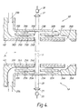
- the uprights 5A and 5B of the main body 5 are shown in more detail. Inside the upright 5A is a light emitter 20 and a lens 21 arranged to produce a light beam 22 which follows the light path 6.
- the light beam 22 passes through a protective window 23A in a wall 32A within the upright 5A and an aperture 24A in a wall 25A of the upright 5A and a wall 26A of the constant area portion 4B into the exhaust gases within the portion 4B.
- a dual air curtain is provided. Clean air under pressure is provided along a clean air duct 27A. This air comes from a fan 28 and an electrostatic precipitator (not shown) which filters the air to remove any smoke and other particles in the ambient air before it is passed along the clean air duct 27A.
- a wall 29A divides the clean air duct 27A into a first clean air passage 30A and a second clean air passage 31A, the first clean air passage 30A is defined between the wall 29A and the wall 25A while the second clean air passage 31A is defined between the wall 29A and the wall 32A.
- the wall 29A has an aperture 33A to allow the light beam 22 to pass through it.
- the airflow along the two clean air passages 30A and 31A is parallel to the direction of flow of exhaust gases through the constant area portion 4B, denoted by the arrow 34. This parallel flow helps to reduce the tendency for clean air plumes to be injected into the constant area portion 4B.
- the two clean air passages 30A and 31A recombine downstream of the optical path 6 and the clean air flow is dumped into the exhaust gas flow through an opening 35A. Before the two clean air passages 30A and 31A recombine there is a constriction 36A in the second clean air passage 31A, so that the air pressure within the second clean air passage 31A is always greater than the air pressure within the second clean air passage 30A.
- the clean air pressure in the first clean air passage 30A need not be as high as in prior art clean air systems because some leakage of exhaust gases into the first clean air passage 30A can be tolerated when the engine is running at full speed and the exhaust gases are at a high pressure without any contamination of the window 23A.
- the engine is running at a lower speed or idling and the exhaust gas pressure is reduced it is less likely that clean air will escape into the constant volume portion 4B and produce a clean air plume along the optical path 6.
- the first clean air passage 30A can be made very narrow because the second clean air passage 31A is acting as a back up to it, as a result the change in the length of the optical path 6 passing through exhaust gases due to penetration of the first clean air passage 30A by exhaust gases is small, reducing changes in the apparent opacity due to this change in path length.
- a similar air curtain system is used in the second upright 5B to prevent particle deposition on a window 23B.
- Behind the window 23B is a lens 37 arranged to focus the light beam 22 onto a photosensor 38.
- a handle 39 is secured to the main body 5 to allow the sensor 1 to be held in position with the input tube 3 inside a vehicle exhaust pipe 2.
- Power for the compressor 25, light emitter 20, photodetector 38 and associated electronics is provided by batteries attached to the main body 5. This allows the sensor 1 to be readily portable for spot-checks of vehicles, but if it is to be used in one place only a lead to plug into mains power could be used.
- the sensing portion 4 of the particle sensor is located against the input tube 3 by a push fit seal formed by a resilient gasket, and is releasably attached to the main body 5 by two catches (not shown), one on each of the uprights 5A and 5B. This allows the sensing portion to be removed and replaced as needed in the event of damage or to allow cleaning out of soot deposited from the exhaust gases.
- the sensing portion 4 can be removed and an optical filter having a known transmission coefficient can be placed in the light path 6.
- the electrostatic precipitator could be replaced by any other filter type, such as a mesh filter, to remove particles from the air used in the air curtains.
- a remote air intake for example on the end of a flexible hose attached to the sensor, could be used to reduce the filtering required by obtaining relatively clean air from a region away from the vehicle exhaust pipe.
- the compressor and filter could be omitted from the sensor and clean compressed air supplied by a hose from a fixed remote compressor and filter.
- baffles 7 within the transition portion 4A only, it is equally possible to have the baffles continuing into the constant area portion 4B or starting in the inlet tube 3 if necessary.
- the exact configuration of baffles used will depend on the precise sizes and shapes of the inlet tube 3, transition portion 4A and constant area portion 4B.
- obstructions could also be placed to slow the gas flow in the centre of the transition portion 4A.
- the number of second baffles 8 used, and thus the number of seperate channels into which the outlet end of the constant area portion 4B is divided could be altered, depending on the width and length available and the degree of wind induced swirl expected.
- the two walls 25 and 26 could be replaced by one wall forming part of the sensing portion 4 and cooperating with the remaining walls which are part of the uprights 5 to form the clean air curtains.
- the walls defining the clean air passages can be divided between the sensing portion 4 and the uprights.
- One other preferred way is to have the windows 23 attached to the uprights 5 and all of the other parts of the clean air curtain arrangements attached to the sensing portion 4.
- an optical filter having a known transmission coefficient can be placed in the light path 6 by inserting it between the second baffles 8.
- any other form of air compressor could be used.
Landscapes
- Physics & Mathematics (AREA)
- Health & Medical Sciences (AREA)
- Life Sciences & Earth Sciences (AREA)
- Chemical & Material Sciences (AREA)
- Analytical Chemistry (AREA)
- Biochemistry (AREA)
- General Health & Medical Sciences (AREA)
- General Physics & Mathematics (AREA)
- Immunology (AREA)
- Pathology (AREA)
- Optical Measuring Cells (AREA)
- Investigating Or Analysing Materials By Optical Means (AREA)
Applications Claiming Priority (2)
| Application Number | Priority Date | Filing Date | Title |
|---|---|---|---|
| GB9122375 | 1991-10-22 | ||
| GB9122375A GB2260809B (en) | 1991-10-22 | 1991-10-22 | Exhaust gas particle sensor |
Publications (2)
| Publication Number | Publication Date |
|---|---|
| EP0539202A2 true EP0539202A2 (de) | 1993-04-28 |
| EP0539202A3 EP0539202A3 (en) | 1993-06-16 |
Family
ID=10703323
Family Applications (1)
| Application Number | Title | Priority Date | Filing Date |
|---|---|---|---|
| EP19920309677 Ceased EP0539202A3 (en) | 1991-10-22 | 1992-10-22 | Exhaust gas particle sensor |
Country Status (5)
| Country | Link |
|---|---|
| US (1) | US5374992A (de) |
| EP (1) | EP0539202A3 (de) |
| JP (1) | JPH05240764A (de) |
| GB (1) | GB2260809B (de) |
| MX (1) | MX9206068A (de) |
Cited By (6)
| Publication number | Priority date | Publication date | Assignee | Title |
|---|---|---|---|---|
| WO2006104871A1 (en) * | 2005-03-28 | 2006-10-05 | Honeywell International Inc. | Air purged optical densitometer |
| WO2007015810A3 (en) * | 2005-07-29 | 2007-04-19 | Corning Inc | Method, system and apparatus for detecting defects in a honeycomb body using a particulate fluid |
| FR2928000A1 (fr) * | 2008-02-21 | 2009-08-28 | Inst Francais Du Petrole | Procede et dispositif de mesure du niveau d'opacite de gaz d'echappement emis par un moteur diesel |
| US8234909B2 (en) | 2009-08-26 | 2012-08-07 | Corning Incorporated | Method and apparatus for inspecting ceramic wall flow filters |
| AT517420A1 (de) * | 2015-06-22 | 2017-01-15 | Avl Ditest Gmbh | Messvorrichtung und Messverfahren zur Driftüberwachung von optischen Systemen |
| WO2021238569A1 (zh) * | 2020-05-26 | 2021-12-02 | 江苏友穗传感科技股份有限公司 | 一种风帘结构油烟传感器 |
Families Citing this family (12)
| Publication number | Priority date | Publication date | Assignee | Title |
|---|---|---|---|---|
| US5589629A (en) * | 1995-04-25 | 1996-12-31 | Quinn; Stephen J. | Method and apparatus for testing vehicle exhaust emissions |
| US6890080B2 (en) * | 2002-01-25 | 2005-05-10 | Ircon, Inc. | Air purge system for optical sensor |
| CA2521584C (en) * | 2003-04-11 | 2012-07-31 | Stockhausen, Inc. | A reduced-emissions fossil-fuel-fired system |
| JP4959156B2 (ja) | 2004-11-29 | 2012-06-20 | 三菱重工業株式会社 | 熱回収設備 |
| JP2011094962A (ja) * | 2004-11-29 | 2011-05-12 | Mitsubishi Heavy Ind Ltd | 熱回収設備 |
| FR3005738B1 (fr) * | 2013-05-14 | 2016-02-05 | Capelec | Opacimetre pour la detection des faibles niveaux de polluants dans un gaz d'echappement |
| CN103411865B (zh) * | 2013-08-09 | 2015-11-18 | 浙江浙大鸣泉科技有限公司 | 一种透射式烟度计的光学平台 |
| WO2015193374A1 (en) * | 2014-06-19 | 2015-12-23 | Danfoss Ixa A/S | Probe for gas sensor with gas split sample gas flow |
| KR101795173B1 (ko) | 2015-12-02 | 2017-11-07 | 현대자동차주식회사 | 차량의 실내온도 및 미세먼지 동시 측정 장치 |
| KR20180082076A (ko) * | 2017-01-10 | 2018-07-18 | 현대자동차주식회사 | 유속 제어 기능을 갖는 먼지센서 |
| WO2019201449A1 (en) * | 2018-04-20 | 2019-10-24 | Flo2R Aps | Gas analyser system |
| US12055477B2 (en) | 2021-09-29 | 2024-08-06 | Kidde Technologies, Inc. | Compressed gas cleaning of windows in particle concentration measurement device |
Family Cites Families (12)
| Publication number | Priority date | Publication date | Assignee | Title |
|---|---|---|---|---|
| GB643867A (en) * | 1945-10-02 | 1950-09-27 | C O Two Fire Equipment Co | Smoke detector and signal |
| CH417405A (de) * | 1964-07-14 | 1966-07-15 | Cerberus Ag Werk Fuer Elektron | Vorrichtung zur Feststellung von Aerosolen in Luft |
| NL7013121A (de) * | 1969-09-17 | 1971-03-19 | ||
| US3833305A (en) * | 1969-09-17 | 1974-09-03 | Commercial Electronics Inc | Gas analyzing apparatus |
| GB1425564A (en) * | 1972-02-09 | 1976-02-18 | Nat Res Dev | Opacimeters |
| GB1549193A (en) * | 1975-04-29 | 1979-08-01 | Hartridge Ltd Leslie | Apparatus for measuring smoke density |
| US4206630A (en) * | 1979-03-12 | 1980-06-10 | Econics Corporation | Sample chamber for gas analyzer |
| US4277131A (en) * | 1980-01-29 | 1981-07-07 | The United States Of America As Represented By The Administrator Of The United States Environmental Protection Agency | Antifouling window assembly |
| US4413911A (en) * | 1981-04-24 | 1983-11-08 | Measurex Corporation | Gas analyzer with fluid curtain |
| US4662758A (en) * | 1983-05-18 | 1987-05-05 | Nippondenso Co., Ltd. | Optical detector assembly |
| US4746215A (en) * | 1986-04-24 | 1988-05-24 | Pacific Scientific Company | Particle counter air inlet assembly |
| US5011286A (en) * | 1989-08-03 | 1991-04-30 | Met One, Inc. | Multisensor particle counter utilizing a single energy source |
-
1991
- 1991-10-22 GB GB9122375A patent/GB2260809B/en not_active Expired - Fee Related
-
1992
- 1992-10-20 US US07/963,493 patent/US5374992A/en not_active Expired - Fee Related
- 1992-10-22 JP JP4325894A patent/JPH05240764A/ja active Pending
- 1992-10-22 EP EP19920309677 patent/EP0539202A3/en not_active Ceased
- 1992-10-22 MX MX9206068A patent/MX9206068A/es not_active IP Right Cessation
Cited By (10)
| Publication number | Priority date | Publication date | Assignee | Title |
|---|---|---|---|---|
| WO2006104871A1 (en) * | 2005-03-28 | 2006-10-05 | Honeywell International Inc. | Air purged optical densitometer |
| US7319524B2 (en) | 2005-03-28 | 2008-01-15 | Honeywell International, Inc. | Air purged optical densitometer |
| WO2007015810A3 (en) * | 2005-07-29 | 2007-04-19 | Corning Inc | Method, system and apparatus for detecting defects in a honeycomb body using a particulate fluid |
| US7648549B2 (en) | 2005-07-29 | 2010-01-19 | Corning Incorporated | Method, system and apparatus for detecting defects in a honeycomb body using a particulate fluid |
| FR2928000A1 (fr) * | 2008-02-21 | 2009-08-28 | Inst Francais Du Petrole | Procede et dispositif de mesure du niveau d'opacite de gaz d'echappement emis par un moteur diesel |
| WO2009115682A3 (fr) * | 2008-02-21 | 2009-12-30 | Ifp | Procede et dispositif de mesure du niveau d'opacite de gaz d'echappement emis par un moteur diesel |
| US8234909B2 (en) | 2009-08-26 | 2012-08-07 | Corning Incorporated | Method and apparatus for inspecting ceramic wall flow filters |
| AT517420A1 (de) * | 2015-06-22 | 2017-01-15 | Avl Ditest Gmbh | Messvorrichtung und Messverfahren zur Driftüberwachung von optischen Systemen |
| AT517420B1 (de) * | 2015-06-22 | 2017-08-15 | Avl Ditest Gmbh | Messvorrichtung und Messverfahren zur Driftüberwachung von optischen Systemen |
| WO2021238569A1 (zh) * | 2020-05-26 | 2021-12-02 | 江苏友穗传感科技股份有限公司 | 一种风帘结构油烟传感器 |
Also Published As
| Publication number | Publication date |
|---|---|
| GB2260809A8 (en) | 1993-04-28 |
| GB9122375D0 (en) | 1991-12-04 |
| US5374992A (en) | 1994-12-20 |
| MX9206068A (es) | 1993-10-01 |
| JPH05240764A (ja) | 1993-09-17 |
| GB2260809A (en) | 1993-04-28 |
| GB2260809B (en) | 1996-04-03 |
| EP0539202A3 (en) | 1993-06-16 |
Similar Documents
| Publication | Publication Date | Title |
|---|---|---|
| US5374992A (en) | Exhaust gas particle sensor | |
| US3628028A (en) | Window cleaning apparatus for photometric instruments | |
| US4836689A (en) | Asymmetric purge air system for cleaning a lens | |
| KR900003054B1 (ko) | 불투명도의 모니터의 필터세척장치 | |
| US6267006B1 (en) | Air induction assembly for a mass air flow sensor | |
| US4786188A (en) | Purge air system for a combustion instrument | |
| JPH01500060A (ja) | 微粒子カウンター空気吸入アセンブリ | |
| US5592296A (en) | Exhaust gas particle sensor | |
| JP2000304585A (ja) | 流量計測装置 | |
| EP0087621B1 (de) | Luftströmungsmesser für eine Brennkraftmaschine | |
| EP0521725B1 (de) | Rauchmessgerät | |
| JP2003529756A (ja) | 導管内を流れる媒体の少なくとも1つのパラメータを測定する装置 | |
| US7546762B2 (en) | Acute angle pressure sensor probe and method | |
| US5852398A (en) | Apparatus for indicating failure of an air filtration system in a diesel engine | |
| GB1471335A (en) | Apparatus for use in monitoring a stream of gases | |
| SU1767394A1 (ru) | Устройство дл измерени дымности отработанных газов | |
| CN212808053U (zh) | 一种透射式烟度计 | |
| GB2252621A (en) | Exhaust gas particle measurement | |
| CN115062866A (zh) | 基于离散光谱贡献的超燃冲压发动机喷焰红外光谱辐射预测方法 | |
| EP4428441B1 (de) | Sensorvorrichtung zur erkennung von flammenpräsenz | |
| Sumal et al. | Bosch mass air flow meter: Status and further aspects | |
| US20170363513A1 (en) | Combustion Gas Sensor Assembly for Engine Control | |
| JPS6345525A (ja) | ボイラ用圧力検出管の異物付着防止装置 | |
| SU928057A1 (ru) | Воздухоочиститель двигател внутреннего сгорани | |
| JPS5821517A (ja) | カルマン渦流量センサ |
Legal Events
| Date | Code | Title | Description |
|---|---|---|---|
| PUAI | Public reference made under article 153(3) epc to a published international application that has entered the european phase |
Free format text: ORIGINAL CODE: 0009012 |
|
| PUAL | Search report despatched |
Free format text: ORIGINAL CODE: 0009013 |
|
| AK | Designated contracting states |
Kind code of ref document: A2 Designated state(s): AT BE CH DE DK ES FR GR IE IT LI NL PT SE |
|
| AK | Designated contracting states |
Kind code of ref document: A3 Designated state(s): AT BE CH DE DK ES FR GR IE IT LI NL PT SE |
|
| 17P | Request for examination filed |
Effective date: 19930715 |
|
| 17Q | First examination report despatched |
Effective date: 19951214 |
|
| 18R | Application refused |
Effective date: 19970210 |