EP0539887A2 - Aiguille de contact - Google Patents
Aiguille de contact Download PDFInfo
- Publication number
- EP0539887A2 EP0539887A2 EP92118192A EP92118192A EP0539887A2 EP 0539887 A2 EP0539887 A2 EP 0539887A2 EP 92118192 A EP92118192 A EP 92118192A EP 92118192 A EP92118192 A EP 92118192A EP 0539887 A2 EP0539887 A2 EP 0539887A2
- Authority
- EP
- European Patent Office
- Prior art keywords
- needle
- needle contact
- safety
- zones
- rail according
- Prior art date
- Legal status (The legal status is an assumption and is not a legal conclusion. Google has not performed a legal analysis and makes no representation as to the accuracy of the status listed.)
- Granted
Links
Images
Classifications
-
- H—ELECTRICITY
- H01—ELECTRIC ELEMENTS
- H01H—ELECTRIC SWITCHES; RELAYS; SELECTORS; EMERGENCY PROTECTIVE DEVICES
- H01H3/00—Mechanisms for operating contacts
- H01H3/02—Operating parts, i.e. for operating driving mechanism by a mechanical force external to the switch
- H01H3/14—Operating parts, i.e. for operating driving mechanism by a mechanical force external to the switch adapted for operation by a part of the human body other than the hand, e.g. by foot
- H01H3/141—Cushion or mat switches
- H01H3/142—Cushion or mat switches of the elongated strip type
-
- E—FIXED CONSTRUCTIONS
- E05—LOCKS; KEYS; WINDOW OR DOOR FITTINGS; SAFES
- E05F—DEVICES FOR MOVING WINGS INTO OPEN OR CLOSED POSITION; CHECKS FOR WINGS; WING FITTINGS NOT OTHERWISE PROVIDED FOR, CONCERNED WITH THE FUNCTIONING OF THE WING
- E05F15/00—Power-operated mechanisms for wings
- E05F15/40—Safety devices, e.g. detection of obstructions or end positions
- E05F15/42—Detection using safety edges
- E05F15/44—Detection using safety edges responsive to changes in electrical conductivity
-
- F—MECHANICAL ENGINEERING; LIGHTING; HEATING; WEAPONS; BLASTING
- F16—ENGINEERING ELEMENTS AND UNITS; GENERAL MEASURES FOR PRODUCING AND MAINTAINING EFFECTIVE FUNCTIONING OF MACHINES OR INSTALLATIONS; THERMAL INSULATION IN GENERAL
- F16P—SAFETY DEVICES IN GENERAL; SAFETY DEVICES FOR PRESSES
- F16P3/00—Safety devices acting in conjunction with the control or operation of a machine; Control arrangements requiring the simultaneous use of two or more parts of the body
- F16P3/12—Safety devices acting in conjunction with the control or operation of a machine; Control arrangements requiring the simultaneous use of two or more parts of the body with means, e.g. feelers, which in case of the presence of a body part of a person in or near the danger zone influence the control or operation of the machine
-
- E—FIXED CONSTRUCTIONS
- E05—LOCKS; KEYS; WINDOW OR DOOR FITTINGS; SAFES
- E05Y—INDEXING SCHEME ASSOCIATED WITH SUBCLASSES E05D AND E05F, RELATING TO CONSTRUCTION ELEMENTS, ELECTRIC CONTROL, POWER SUPPLY, POWER SIGNAL OR TRANSMISSION, USER INTERFACES, MOUNTING OR COUPLING, DETAILS, ACCESSORIES, AUXILIARY OPERATIONS NOT OTHERWISE PROVIDED FOR, APPLICATION THEREOF
- E05Y2600/00—Mounting or coupling arrangements for elements provided for in this subclass
- E05Y2600/40—Mounting location; Visibility of the elements
-
- H—ELECTRICITY
- H01—ELECTRIC ELEMENTS
- H01H—ELECTRIC SWITCHES; RELAYS; SELECTORS; EMERGENCY PROTECTIVE DEVICES
- H01H1/00—Contacts
- H01H1/58—Electric connections to or between contacts; Terminals
Definitions
- the invention relates to a safety contact rail for power-operated systems and for securing machines or rooms with a first and a second section which have electrically conductive zones which are arranged in isolation from one another and which trigger a switching pulse when the safety contact rail is deformed by mutual contact. which can be fed to an evaluation unit via switching lines connected to the zones.
- Such a safety contact rail is known from DE-Gbm 89 13 363.3.
- This safety contact rail is used, for example, in power-operated systems such as rolling gates, rolling grilles etc. as well as for lifting and working platforms and the like, as well as for securing machines or rooms, e.g. can be used as a step protection.
- the safety contact rail is usually manufactured by the meter and individual rails can be joined together using connecting pieces and closed with end pieces.
- the necessary switching cables are attached to the safety contact rail described in the utility model with rents, screws, soldered connections or clips. Although these types of connection have proven themselves in principle, they nevertheless have some weaknesses in the durability of the switching cables with the electrically conductive zones of the safety contact rail.
- the object of the invention is to provide a safety contact rail in which the switching lines can be fastened to the electrically conductive zones in a reliable manner without impairing the deformability of the safety contact rail.
- needle contact elements can be used in the electrically conductive zones of the two sections, to which the switching lines can be attached.
- Such needle contact elements can be easily manufactured as a separate component and, if necessary, can be used in a uniform size for different safety contact rail sizes.
- the needle contact elements can be inserted into prefabricated holes in the zones; however, it is normally intended to insert or press them directly into the zones without prior processing.
- the needle contact elements offer a good and reliable transmission of the switching impulses from the electrically conductive zones to the switching lines and have a secure fit in the zones even after long use of the safety contact rail.
- the first section with the first electrically conductive zone is designed as a hollow rubber profile and the second section with the second electrically conductive zone as a blade-like rib arranged in the hollow rubber profile.
- This design is the most common in a safety contact rail, but in special applications, any other safety contact rail can also be equipped with the needle contact elements according to the invention.
- electrical conductors are embedded in the zones, in each of whose end regions a needle contact element can be inserted.
- Such electrical conductors are preferably made as a flexible wire, preferably composed of a large number of individual wires.
- the needle contact element can be inserted into the electrically conductive zones in the area adjacent to the conductor, or can be inserted directly into the conductors made of individual wires. This enables a particularly low-resistance - that is, highly conductive - transmission of the switching pulses.
- the needle contact element has a needle contact pin and a needle contact head with a fastening device for the switching line.
- the needle contact pin is usually completely inserted into the zone and has a length that ensures a secure hold and good transmission of the switching implements.
- the needle contact head is arranged centrally or eccentrically at one end of the needle contact pin.
- the choice of arrangement is based on the requirement specified by the design of the safety contact rail.
- the fastening device on the needle contact head of the needle contact element is designed as a screw-type clamping device or as a spring-type clamping device. These are preferred fastening devices that ensure a secure and reliable hold for the switching line.
- the spring clamp device enables a particularly simple assembly of the switching line without additional tools.
- other than the described clamping devices for fastening the switching lines are also conceivable.
- the needle contact pin starting from the head end, has a diameter that increases up to the opposite, free end. This conicity enables the needle contact element to be held very securely in the electrically conductive zones or in or on the electrical conductor embedded in the electrical zones. It is sufficient that the taper over the length of the needle contact pin is only a few tenths of a millimeter is.
- a needle tip is arranged at the free end of the needle contact pin.
- the needle contact tip encloses an angle of 50 to 90 °, but preferably 70.
- a needle tip of this type enables the needle contact element to be inserted into the electrically conductive zones without problems.
- the needle tip designed according to the invention ensures that the needle contact pin is guided exactly along the conductor or within the conductor and does not slide into the surrounding electrically conductive zone.
- the electrically conductive zones have recesses or shoulders on the fastening-side end of the needle contact element. These recesses or shoulders are preferably designed so that the needle contact head projects completely into this recess.
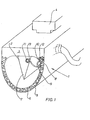
- the safety contact rail according to FIG. 1 essentially has a hollow rubber profile 1, a rib 2 made of electrically conductive rubber being attached inside the hollow rubber profile 1, the base of which is attached to a carrier 4 opposite the electrically non-conductive back 3 of the hollow rubber profile 1 is.
- the carrier 4 is T-shaped and can be inserted and fastened, for example, in a corresponding recess in a roller shutter.
- a wall 5 adjoins the back 3, which forms the actual hollow rubber profile 1 and is electrically conductive, for example due to the inclusion of graphite 6.
- a section 7 of the rib 2 in the form of a cutting edge faces the electrically conductive wall 5.
- the switching lines 8, 9 are fastened by means of needle contact elements 10, 11 in the electrically conductive zones of the wall 5 and the rib 2.
- the needle contact element 10 has a fastening device which is designed as a screw clamping device, while the fastening device of the needle contact element 11 is designed as a spring clamping device.
- a shoulder 12, 13 is arranged and designed such that the head 14a, 14b of a needle contact element 10, 11 projects completely into the latter.
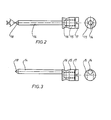
- the needle contact elements 10, 11 each have a needle contact pin 14, which continues in a needle contact head 15.
- the needle contact head 15 has a transverse bore 16 into which the switching line 8, 9 can be inserted with a stripped line part.
- a screw 17 which can be screwed in from the end face of the needle contact head presses the stripped part of the switching line 8, 9 against the wall of the transverse bore 16 and ensures a secure and electrically conductive seat.
- the needle contact head is centered on one end face of the needle contact pin 14, while in the exemplary embodiment according to FIG. 3 the needle contact head is attached eccentrically to the needle contact pin 14.
- a needle tip 18, which encloses an angle of 70 °, is formed on the free end of the needle contact pin 14 opposite the head end.
- the needle contact pin 14 has a diameter that increases up to the opposite free end.
- the diameter of the needle contact pin 14 in the head-side area is, for example, approximately 1.2 mm, while in the area of the needle contact tip 18 it has a diameter of approximately 1.4 mm. Otherwise, the length of the needle contact pin from the needle contact tip 18 to the head 14 is approximately 15 mm, while the needle contact head without the screw has a length of approximately 4 mm.
- the diameter of the needle contact head is approximately 3.5 mm in the exemplary embodiment.
Landscapes
- Engineering & Computer Science (AREA)
- General Engineering & Computer Science (AREA)
- Mechanical Engineering (AREA)
- Connections By Means Of Piercing Elements, Nuts, Or Screws (AREA)
- Lead Frames For Integrated Circuits (AREA)
- Contacts (AREA)
- Infusion, Injection, And Reservoir Apparatuses (AREA)
- Measurement Of The Respiration, Hearing Ability, Form, And Blood Characteristics Of Living Organisms (AREA)
- Electron Sources, Ion Sources (AREA)
- Cold Cathode And The Manufacture (AREA)
Applications Claiming Priority (2)
| Application Number | Priority Date | Filing Date | Title |
|---|---|---|---|
| DE4135890A DE4135890A1 (de) | 1991-10-31 | 1991-10-31 | Nadelkontaktelement |
| DE4135890 | 1991-10-31 |
Publications (3)
| Publication Number | Publication Date |
|---|---|
| EP0539887A2 true EP0539887A2 (fr) | 1993-05-05 |
| EP0539887A3 EP0539887A3 (en) | 1993-09-15 |
| EP0539887B1 EP0539887B1 (fr) | 1997-02-05 |
Family
ID=6443822
Family Applications (1)
| Application Number | Title | Priority Date | Filing Date |
|---|---|---|---|
| EP92118192A Expired - Lifetime EP0539887B1 (fr) | 1991-10-31 | 1992-10-23 | Aiguille de contact |
Country Status (4)
| Country | Link |
|---|---|
| EP (1) | EP0539887B1 (fr) |
| AT (1) | ATE148779T1 (fr) |
| DE (2) | DE4135890A1 (fr) |
| ES (1) | ES2097257T3 (fr) |
Cited By (6)
| Publication number | Priority date | Publication date | Assignee | Title |
|---|---|---|---|---|
| EP0638701A3 (fr) * | 1993-08-09 | 1995-04-19 | Metzeler Automotive Profiles | Sécurité anti-pincement pour dispositifs de fermeture motorisés. |
| EP0654575A1 (fr) * | 1993-11-22 | 1995-05-24 | Karlheinz Beckhausen | Rail de contact de sécurité avec une couche protective |
| EP0728893A1 (fr) * | 1995-02-24 | 1996-08-28 | REHAU AG + Co | Bordure de sécurité pour lignes électriques |
| FR2791173A1 (fr) * | 1999-03-19 | 2000-09-22 | Electronique Controle Mesure | Dispositif de detection d'appui et de passage de roue de vehicule sur une chaussee utilisant un caoutchouc conducteur et son procede de pose |
| US6568130B1 (en) * | 1999-09-17 | 2003-05-27 | Marantec Antriebs-Und Steuerungstechnik Gmbh & Co. Kg | Safety contact rail including a freely moving contact element and hollow profile situated thereabout |
| WO2012025198A1 (fr) * | 2010-08-27 | 2012-03-01 | Menz Juergen | Connexion électrique d'un dispositif de commutation de sécurité |
Families Citing this family (1)
| Publication number | Priority date | Publication date | Assignee | Title |
|---|---|---|---|---|
| DE10306436A1 (de) * | 2003-02-15 | 2004-08-26 | Menz, Jürgen | Sicherheitseinrichtung |
Family Cites Families (9)
| Publication number | Priority date | Publication date | Assignee | Title |
|---|---|---|---|---|
| SU866579A1 (ru) * | 1980-01-07 | 1981-09-23 | Предприятие П/Я Г-4755 | Кабель дл аварийного отключени |
| DE3304400C3 (de) * | 1983-02-09 | 1994-02-24 | Karlheinz Beckhausen | Sicherheitskontaktschiene für kraftbetätigte Anlagen |
| DE3411198A1 (de) * | 1984-03-27 | 1985-10-03 | OPTO - electronic GmbH, 7931 Unterstadion | Verfahren zur signalerzeugung und signalauswertung unter verwendung eines gummikoerpers |
| DE3640464A1 (de) * | 1986-11-27 | 1988-06-09 | Siemens Ag | Mehradrige als flachleitung ausgebildete anschluss- oder verbindungsschnur |
| DE8805557U1 (de) * | 1988-04-27 | 1988-12-15 | Malkmus-Dörnemann, Carola, Dr., 38259 Salzgitter | Als elektrische Schaltvorrichtung ausgebildetes Gummihohlprofil |
| DE8809726U1 (de) * | 1988-07-30 | 1988-09-22 | Beckhausen, Karlheinz, 50931 Köln | Verbindungs- und/oder Endstück für ein Gummihohlprofil an Sicherheitskontaktschienen und dgl. |
| DE3909548A1 (de) * | 1989-03-22 | 1990-09-27 | Hirschmann Richard Gmbh Co | Anschlussklemme |
| DE8913363U1 (de) * | 1989-11-13 | 1990-03-22 | Beckhausen, Karlheinz, 50931 Köln | Sicherheitskontaktschiene |
| DE4029929C2 (de) * | 1990-09-21 | 1999-11-04 | G E K Ges Fuer Elektrotechnisc | Sicherheits-Schaltleiste |
-
1991
- 1991-10-31 DE DE4135890A patent/DE4135890A1/de not_active Withdrawn
-
1992
- 1992-10-23 ES ES92118192T patent/ES2097257T3/es not_active Expired - Lifetime
- 1992-10-23 EP EP92118192A patent/EP0539887B1/fr not_active Expired - Lifetime
- 1992-10-23 AT AT92118192T patent/ATE148779T1/de not_active IP Right Cessation
- 1992-10-23 DE DE59208010T patent/DE59208010D1/de not_active Expired - Lifetime
Cited By (8)
| Publication number | Priority date | Publication date | Assignee | Title |
|---|---|---|---|---|
| EP0638701A3 (fr) * | 1993-08-09 | 1995-04-19 | Metzeler Automotive Profiles | Sécurité anti-pincement pour dispositifs de fermeture motorisés. |
| EP0654575A1 (fr) * | 1993-11-22 | 1995-05-24 | Karlheinz Beckhausen | Rail de contact de sécurité avec une couche protective |
| EP0728893A1 (fr) * | 1995-02-24 | 1996-08-28 | REHAU AG + Co | Bordure de sécurité pour lignes électriques |
| FR2791173A1 (fr) * | 1999-03-19 | 2000-09-22 | Electronique Controle Mesure | Dispositif de detection d'appui et de passage de roue de vehicule sur une chaussee utilisant un caoutchouc conducteur et son procede de pose |
| WO2000057442A1 (fr) * | 1999-03-19 | 2000-09-28 | Electronique Controle Mesure | Dispositif de detection d'appui et de passage de roue de vehicule sur une chaussee utilisant un caoutchouc conducteur et son procede de pose |
| US6492604B1 (en) | 1999-03-19 | 2002-12-10 | Electronique Controle Mesure | Device for detecting pressure and passage of a vehicle wheel on a pavement using a conductive rubber and method for installing same |
| US6568130B1 (en) * | 1999-09-17 | 2003-05-27 | Marantec Antriebs-Und Steuerungstechnik Gmbh & Co. Kg | Safety contact rail including a freely moving contact element and hollow profile situated thereabout |
| WO2012025198A1 (fr) * | 2010-08-27 | 2012-03-01 | Menz Juergen | Connexion électrique d'un dispositif de commutation de sécurité |
Also Published As
| Publication number | Publication date |
|---|---|
| ES2097257T3 (es) | 1997-04-01 |
| EP0539887A3 (en) | 1993-09-15 |
| ATE148779T1 (de) | 1997-02-15 |
| EP0539887B1 (fr) | 1997-02-05 |
| DE59208010D1 (de) | 1997-03-20 |
| DE4135890A1 (de) | 1993-05-06 |
Similar Documents
| Publication | Publication Date | Title |
|---|---|---|
| DE102013223694B4 (de) | Verbesserter mehrpoliger elektrischer Steckverbinder mit Federkontakten | |
| EP1507315B1 (fr) | Pont à fiche pour des borniers électriques et borniers associées | |
| EP1251590B1 (fr) | Borne électrique | |
| EP3342005B1 (fr) | Bloc de jonction électrique | |
| DE69402983T2 (de) | Elektrische vorrichtung in modulbauweise mit beruehrungsschutz fuer anschlussklemmen | |
| EP3734771B1 (fr) | Ensemble comprenant un connecteur électrique et un élément fonctionnel | |
| EP3259807B1 (fr) | Bloc de jonction électrique | |
| DE8125854U1 (de) | Als elektrischer Stecker oder als Steckdose oder als Kupplungsdose ausgebildetes Installationsteil | |
| EP0539887B1 (fr) | Aiguille de contact | |
| DE102007045400B4 (de) | Netzstecker | |
| DE602005004414T2 (de) | Vorrichtung zur elektrischen verbindung diskontinuierlicher leiter | |
| EP0654576B1 (fr) | Aiguille de contact d'un rail de contact de sécurité | |
| DE4400555A1 (de) | Kurzschlussfreier Steckverbinder | |
| EP3221928B1 (fr) | Bloc de jonction | |
| DE8809666U1 (de) | Anschlußklemme für Sammelschienen | |
| DE19708914C1 (de) | Prüfstecker für Reihenklemmen | |
| DE2613704C2 (de) | Elektrische Steckvorrichtung | |
| DE102016113524A1 (de) | Anschlusseinrichtung zum Anschluss eines Leiters an eine Sammelschiene | |
| DE19525801A1 (de) | Vorrichtung zum elektrisch leitenden Verbinden von zwei elektrischen Leitungen | |
| EP3857584B1 (fr) | Fiche pour un profilé de sécurité et une baguette de commutation | |
| DE10329775B4 (de) | Kabelanschluß- oder -verbindungseinrichtung | |
| EP1611654B1 (fr) | Dispositif d'adaptation pour des appareils d'installation pour des barres omnibus | |
| EP2262062B1 (fr) | Connecteur à fiches | |
| DE102019104574A1 (de) | Stiftleiste zur Anordnung in einer Wandöffnung | |
| DE3710708C2 (fr) |
Legal Events
| Date | Code | Title | Description |
|---|---|---|---|
| PUAI | Public reference made under article 153(3) epc to a published international application that has entered the european phase |
Free format text: ORIGINAL CODE: 0009012 |
|
| AK | Designated contracting states |
Kind code of ref document: A2 Designated state(s): AT BE CH DE DK ES FR GB IT LI LU NL SE |
|
| PUAL | Search report despatched |
Free format text: ORIGINAL CODE: 0009013 |
|
| RHK1 | Main classification (correction) |
Ipc: F16P 3/12 |
|
| AK | Designated contracting states |
Kind code of ref document: A3 Designated state(s): AT BE CH DE DK ES FR GB IT LI LU NL SE |
|
| 17P | Request for examination filed |
Effective date: 19931022 |
|
| 17Q | First examination report despatched |
Effective date: 19940919 |
|
| GRAG | Despatch of communication of intention to grant |
Free format text: ORIGINAL CODE: EPIDOS AGRA |
|
| GRAH | Despatch of communication of intention to grant a patent |
Free format text: ORIGINAL CODE: EPIDOS IGRA |
|
| GRAH | Despatch of communication of intention to grant a patent |
Free format text: ORIGINAL CODE: EPIDOS IGRA |
|
| GRAA | (expected) grant |
Free format text: ORIGINAL CODE: 0009210 |
|
| RAP1 | Party data changed (applicant data changed or rights of an application transferred) |
Owner name: BECKHAUSEN, KARLHEINZ |
|
| AK | Designated contracting states |
Kind code of ref document: B1 Designated state(s): AT BE CH DE DK ES FR GB IT LI LU NL SE |
|
| PG25 | Lapsed in a contracting state [announced via postgrant information from national office to epo] |
Ref country code: GB Effective date: 19970205 Ref country code: DK Effective date: 19970205 Ref country code: NL Free format text: LAPSE BECAUSE OF FAILURE TO SUBMIT A TRANSLATION OF THE DESCRIPTION OR TO PAY THE FEE WITHIN THE PRESCRIBED TIME-LIMIT Effective date: 19970205 |
|
| REF | Corresponds to: |
Ref document number: 148779 Country of ref document: AT Date of ref document: 19970215 Kind code of ref document: T |
|
| REG | Reference to a national code |
Ref country code: CH Ref legal event code: EP Ref country code: CH Ref legal event code: NV Representative=s name: R. A. EGLI & CO. PATENTANWAELTE |
|
| ET | Fr: translation filed | ||
| REF | Corresponds to: |
Ref document number: 59208010 Country of ref document: DE Date of ref document: 19970320 |
|
| REG | Reference to a national code |
Ref country code: ES Ref legal event code: FG2A Ref document number: 2097257 Country of ref document: ES Kind code of ref document: T3 |
|
| ITF | It: translation for a ep patent filed | ||
| PG25 | Lapsed in a contracting state [announced via postgrant information from national office to epo] |
Ref country code: SE Effective date: 19970505 |
|
| NLV1 | Nl: lapsed or annulled due to failure to fulfill the requirements of art. 29p and 29m of the patents act | ||
| GBV | Gb: ep patent (uk) treated as always having been void in accordance with gb section 77(7)/1977 [no translation filed] |
Effective date: 19970205 |
|
| PG25 | Lapsed in a contracting state [announced via postgrant information from national office to epo] |
Ref country code: LU Free format text: LAPSE BECAUSE OF NON-PAYMENT OF DUE FEES Effective date: 19971023 |
|
| PG25 | Lapsed in a contracting state [announced via postgrant information from national office to epo] |
Ref country code: BE Free format text: LAPSE BECAUSE OF NON-PAYMENT OF DUE FEES Effective date: 19971031 |
|
| PLBE | No opposition filed within time limit |
Free format text: ORIGINAL CODE: 0009261 |
|
| STAA | Information on the status of an ep patent application or granted ep patent |
Free format text: STATUS: NO OPPOSITION FILED WITHIN TIME LIMIT |
|
| 26N | No opposition filed | ||
| BERE | Be: lapsed |
Owner name: BECKHAUSEN KARLHEINZ Effective date: 19971031 |
|
| PGFP | Annual fee paid to national office [announced via postgrant information from national office to epo] |
Ref country code: ES Payment date: 20091006 Year of fee payment: 18 Ref country code: DE Payment date: 20091012 Year of fee payment: 18 Ref country code: AT Payment date: 20091001 Year of fee payment: 18 |
|
| PGFP | Annual fee paid to national office [announced via postgrant information from national office to epo] |
Ref country code: IT Payment date: 20091027 Year of fee payment: 18 Ref country code: FR Payment date: 20091117 Year of fee payment: 18 Ref country code: CH Payment date: 20100126 Year of fee payment: 18 |
|
| REG | Reference to a national code |
Ref country code: CH Ref legal event code: PL |
|
| PG25 | Lapsed in a contracting state [announced via postgrant information from national office to epo] |
Ref country code: FR Free format text: LAPSE BECAUSE OF NON-PAYMENT OF DUE FEES Effective date: 20101102 Ref country code: LI Free format text: LAPSE BECAUSE OF NON-PAYMENT OF DUE FEES Effective date: 20101031 Ref country code: CH Free format text: LAPSE BECAUSE OF NON-PAYMENT OF DUE FEES Effective date: 20101031 |
|
| REG | Reference to a national code |
Ref country code: FR Ref legal event code: ST Effective date: 20110630 |
|
| PG25 | Lapsed in a contracting state [announced via postgrant information from national office to epo] |
Ref country code: AT Free format text: LAPSE BECAUSE OF NON-PAYMENT OF DUE FEES Effective date: 20101023 |
|
| REG | Reference to a national code |
Ref country code: DE Ref legal event code: R119 Ref document number: 59208010 Country of ref document: DE Effective date: 20110502 |
|
| REG | Reference to a national code |
Ref country code: ES Ref legal event code: FD2A Effective date: 20111118 |
|
| PG25 | Lapsed in a contracting state [announced via postgrant information from national office to epo] |
Ref country code: IT Free format text: LAPSE BECAUSE OF NON-PAYMENT OF DUE FEES Effective date: 20101023 |
|
| PG25 | Lapsed in a contracting state [announced via postgrant information from national office to epo] |
Ref country code: ES Free format text: LAPSE BECAUSE OF NON-PAYMENT OF DUE FEES Effective date: 20101024 |
|
| PG25 | Lapsed in a contracting state [announced via postgrant information from national office to epo] |
Ref country code: DE Free format text: LAPSE BECAUSE OF NON-PAYMENT OF DUE FEES Effective date: 20110502 |