EP0540045A1 - Dispositif de vulcanisation pour pneumatiques de véhicule routier - Google Patents
Dispositif de vulcanisation pour pneumatiques de véhicule routier Download PDFInfo
- Publication number
- EP0540045A1 EP0540045A1 EP92118687A EP92118687A EP0540045A1 EP 0540045 A1 EP0540045 A1 EP 0540045A1 EP 92118687 A EP92118687 A EP 92118687A EP 92118687 A EP92118687 A EP 92118687A EP 0540045 A1 EP0540045 A1 EP 0540045A1
- Authority
- EP
- European Patent Office
- Prior art keywords
- mold
- fact
- curing unit
- portions
- annular
- Prior art date
- Legal status (The legal status is an assumption and is not a legal conclusion. Google has not performed a legal analysis and makes no representation as to the accuracy of the status listed.)
- Granted
Links
- 238000010438 heat treatment Methods 0.000 claims abstract description 25
- 238000012856 packing Methods 0.000 claims abstract description 5
- 239000011324 bead Substances 0.000 claims abstract description 4
- 239000012530 fluid Substances 0.000 claims description 8
- 230000006835 compression Effects 0.000 claims description 6
- 238000007906 compression Methods 0.000 claims description 6
- 230000000916 dilatatory effect Effects 0.000 claims 1
- IJGRMHOSHXDMSA-UHFFFAOYSA-N Atomic nitrogen Chemical compound N#N IJGRMHOSHXDMSA-UHFFFAOYSA-N 0.000 description 6
- 239000007789 gas Substances 0.000 description 5
- 238000000034 method Methods 0.000 description 4
- 229910052757 nitrogen Inorganic materials 0.000 description 3
- 230000013011 mating Effects 0.000 description 2
- 239000012528 membrane Substances 0.000 description 2
- 239000000446 fuel Substances 0.000 description 1
- 238000004519 manufacturing process Methods 0.000 description 1
- 239000002184 metal Substances 0.000 description 1
- 238000002156 mixing Methods 0.000 description 1
- 230000002093 peripheral effect Effects 0.000 description 1
Images




Classifications
-
- B—PERFORMING OPERATIONS; TRANSPORTING
- B29—WORKING OF PLASTICS; WORKING OF SUBSTANCES IN A PLASTIC STATE IN GENERAL
- B29D—PRODUCING PARTICULAR ARTICLES FROM PLASTICS OR FROM SUBSTANCES IN A PLASTIC STATE
- B29D30/00—Producing pneumatic or solid tyres or parts thereof
- B29D30/06—Pneumatic tyres or parts thereof (e.g. produced by casting, moulding, compression moulding, injection moulding, centrifugal casting)
- B29D30/0601—Vulcanising tyres; Vulcanising presses for tyres
-
- B—PERFORMING OPERATIONS; TRANSPORTING
- B29—WORKING OF PLASTICS; WORKING OF SUBSTANCES IN A PLASTIC STATE IN GENERAL
- B29D—PRODUCING PARTICULAR ARTICLES FROM PLASTICS OR FROM SUBSTANCES IN A PLASTIC STATE
- B29D30/00—Producing pneumatic or solid tyres or parts thereof
- B29D30/06—Pneumatic tyres or parts thereof (e.g. produced by casting, moulding, compression moulding, injection moulding, centrifugal casting)
- B29D30/0601—Vulcanising tyres; Vulcanising presses for tyres
- B29D30/0662—Accessories, details or auxiliary operations
-
- B—PERFORMING OPERATIONS; TRANSPORTING
- B29—WORKING OF PLASTICS; WORKING OF SUBSTANCES IN A PLASTIC STATE IN GENERAL
- B29D—PRODUCING PARTICULAR ARTICLES FROM PLASTICS OR FROM SUBSTANCES IN A PLASTIC STATE
- B29D30/00—Producing pneumatic or solid tyres or parts thereof
- B29D30/06—Pneumatic tyres or parts thereof (e.g. produced by casting, moulding, compression moulding, injection moulding, centrifugal casting)
- B29D30/0601—Vulcanising tyres; Vulcanising presses for tyres
- B29D30/0662—Accessories, details or auxiliary operations
- B29D2030/0666—Heating by using fluids
- B29D2030/0667—Circulating the fluids, e.g. introducing and removing them into and from the moulds; devices therefor
- B29D2030/0669—Circulating the fluids, e.g. introducing and removing them into and from the moulds; devices therefor the fluids being circulated by a turbine type pump associated with the mould, e.g. positioned in the mould
-
- B—PERFORMING OPERATIONS; TRANSPORTING
- B29—WORKING OF PLASTICS; WORKING OF SUBSTANCES IN A PLASTIC STATE IN GENERAL
- B29D—PRODUCING PARTICULAR ARTICLES FROM PLASTICS OR FROM SUBSTANCES IN A PLASTIC STATE
- B29D30/00—Producing pneumatic or solid tyres or parts thereof
- B29D30/06—Pneumatic tyres or parts thereof (e.g. produced by casting, moulding, compression moulding, injection moulding, centrifugal casting)
- B29D30/0601—Vulcanising tyres; Vulcanising presses for tyres
- B29D30/0662—Accessories, details or auxiliary operations
- B29D2030/0666—Heating by using fluids
- B29D2030/0667—Circulating the fluids, e.g. introducing and removing them into and from the moulds; devices therefor
- B29D2030/067—Circulating the fluids, e.g. introducing and removing them into and from the moulds; devices therefor the vulcanizing fluids being gases or vapours
Definitions
- the present invention relates to a road vehicle tire curing device.
- Italian Patent Application n.TO91A 000820 to which full reference is made herein in the interest of full disclosure, relates to a road vehicle tire manufacturing process whereby a green tire is assembled inside an annular forming mold consisting of an outer annular body; two inner annular supports, each fitted to a respective bead portion of the tire; and two lateral annular plates connecting the two inner annular supports and the outer annular body.
- the tire so formed is kept inside the forming mold until after curing.
- Yet a further object of the present invention is to provide a curing device designed to receive not only the aforementioned forming mold but also any type of curing mold currently employed on standard curing presses.
- a road vehicle tire curing device comprising a toroidal mold for receiving said tire and having a first and second coaxial cylindrical inner surface; external means for heating said mold; and a gas curing unit connected to said mold and comprising a first and second portion on either side of the mold; characterized by the fact that each said cylindrical surface defines a seat for a respective said portion of the curing unit; a releasable joint being provided for connecting the two portions of the curing unit through the mold; and one of the two portions of the curing unit comprising axial thrust means for packing the mold and external heating means against the other portion.
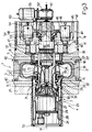
- Device 1 indicates a device for curing road vehicle tires 2.
- Device 1 comprises a toroidal curing mold 3; a gas curing unit 4 connected to mold 3; two annular heating plates 5 facing opposite axial ends of mold 3; and two annular insulating plates 6, each connected to and outwardly insulating a respective heating plate 5.
- Curing unit 4 comprises a first and second portion 7 and 8 on either side of mold 3, which consists of a forming mold for a green tire 2, as described in Italian Patent Application n.TO91A 000820, to which full reference is made herein in the interest of full disclosure.
- Mold 3 comprises a first and second inner annular support 9 and 10 for supporting respective bead portions 11 of tire 2.
- Annular supports 9 and 10 are defined internally by respective cylindrical surfaces 12 and 13 coaxial with axis 14, and are connected in releasable manner to the inner edge of respective annular plates 15 and 16, the outer edge of each of which is connected in releasable manner to a respective axial end of an outer annular body 17.
- annular body 17 defines a toroidal chamber 18 having an inner surface negatively reproducing the outer surface of finished tire 2, and accessible from the inside through an annular opening 19 defined between annular supports 9 and 10 and extending about axis 14.
- annular plates 15 and 16 present respective outer lateral surfaces 20 and 21 projecting slightly outwards in relation to respective end surfaces 22 of annular body 17.
- Portion 7 of curing unit 4 is positioned coaxial with axis 14, facing annular plate 15 of mold 3, and comprises a supporting frame 23 defined by a tube 24 coaxial with axis 14 and fitted with an annular plate 25 on the end facing mold 3.
- the surface of plate 25 facing mold 3 is fitted with an insulating plate 6 and a heating plate 5 on top of plate 6.
- Tube 24, plate 25 and plates 6 and 5 integral with plate 25 define a through conduit 26 of substantially the same diameter as cylindrical surface 12 of annular support 9.
- Conduit 26 is fitted inside with a turbine device 27 sliding in fluidtight manner, inside conduit 26, between an idle backup position (Fig.s 1 and 2) and a forward operating position (Fig.3).
- Device 27 is of the type described in European Patent Application n. 91111887.5, to which full reference is made herein in the interest of full disclosure.
- Device 27 comprises a tubular body 28 sliding along conduit 26 and housing the drive motor 29 of a fan 30 for circulating heat exchange gas along a pneumatic circuit 31 comprising an annular supply conduit 32 and an annular return conduit 33, the first outside the second, and both coaxial with axis 14.
- Conduits 32 and 33 come out through an annular opening 34 defined between two annular clamping devices 35 coaxial with axis 14, located outwards of the end of tubular body 28 facing mold 3, and connected integral with tubular body 28 for supporting the opposite ends of an optional curing bladder (not shown).
- annular return conduit 33 is defined by an elongated central core 36 housing a heating element 37, and having a cylindrical head 38 extending coaxially with axis 14 towards mold 3 and beyond clamping devices 35, and having an internally threaded dead axial hole 39.
- portion 7 of curing unit 4 is moved between a backup position (Fig.1) wherein heating plate 5 is detached from surface 20 of annular plate 15, and a forward position (Fig.s 2 and 3) wherein heating plate 5 contacts surface 20 and defines a relatively narrow annular opening 40 with surface 22, and wherein conduit 26 and the passage defined by cylindrical surface 12 of annular support 9 are a continuation of each other.
- tubular body 28 slides along conduit 26 between the backup position in Fig.s 1 and 2 and the forward position in Fig.3, wherein annular opening 34 coincides with opening 19, when portion 7 of curing unit 4 is in the forward position, and circuit 31 is closed through toroidal chamber 18.
- portion 8 of curing unit 4 comprises a cup-shaped frame 41 defined by a substantially cylindrical lateral wall 42 coaxial with axis 14 and closed, on the side facing mold 3, by a plate 43 similar to plate 25 and fitted integral with plates 6 and 5 facing annular plate 16 of mold 3.
- frame 41 supports a further cup-shaped body 44 comprising a substantially cylindrical lateral wall 45 coaxial with axis 14 and closed, on the side facing plate 43, by a plate 46, a peripheral portion of which presents a number of equally-spaced through holes 47, each engaged by the body of a hydraulic jack 48 integral with plate 46 and having an output rod 49 connected axially integral with plate 43.
- Plate 46 is fitted integral with a central sleeve 50 extending from plate 46 through a central hole 51 in plate 43, and communicating with a central hole 52 through plate 46.
- Hole 52 and sleeve 50 are engaged in rotary axially-fixed manner by a shaft 53 connected to plate 46 via the interposition of a thrust bearing 54 gripped against plate 46 by a double-ring-nut lock device 55.
- a first end portion of shaft 53 consists of a threaded pin 56 coaxial with axis 14 and constituting one element of a releasable joint 57, the other element of which consists of internally threaded head 38 of core 36.
- Pin 56 is fitted inside a sleeve 58 engaged inside a central hole 59 in plates 5 and 6, and projecting outwards of plate 5 to form a tubular appendix 60, the outside diameter of which is approximately equal to but no larger than the diameter of cylindrical surface 13 of tubular support 10.
- a second end portion of shaft 53 opposite pin 56 is connected to the output shaft 61 of a reduction gear 62 connected to the output of a motor 63 supported on plate 46 by an upright 64.
- portion 8 of curing unit 4 is moved between a backup position (Fig.1) wherein heating plate 5 is detached from surface 21 of annular plate 16, and a forward position (Fig.s 2 and 3) wherein heating plate 5 contacts surface 21 and defines a further relatively narrow annular opening 40 with surface 22, and wherein tubular appendix 60 engages in sliding manner the passage defined by cylindrical surface 13 of annular support 10.
- each annular heating plate 5 presents a sunken annular portion 65, the end surface of which presents a groove 66 closed by an annular cover 67 housed inside annular portion 65 so as to define a number of round concentric conduits 68 connected by radial conduits 69.
- the outermost and innermost conduits 68 communicate externally by means of respective radial inlet and outlet conduits 70 and 71 for a heat exchange fluid.
- conduits 68 house electric resistors (not shown), the terminals of which come out through conduits 70 and 71.
- portions 7 and 8 of curing unit 4 are initially separated, as shown in Fig.1, for inserting mold 3 between portions 7 and 8 and coaxial with axis 14.
- Mold 3 may of course be set up contacting one of portions 7 and 8, e.g. portion 7, so that only one portion need be moved axially for gripping mold 3.
- mold 3 is set up between portions 7 and 8, these are brought together so as to grip mold 3 as shown in Fig.2, wherein plates 5 contact surfaces 20 and 21 of annular plates 15 and 16 of mold 3; appendix 60 of portion 8 engages the seat defined by cylindrical surface 13; and turbine device 27 is in the idle backup position outside the seat defined by cylindrical surface 12.
- turbine device 27 is pushed into the forward operating position through cylindrical surface 12 and mold 3, so as to bring head 38 into contact with pin 56, which is rotated by motor 63 so as to screw inside hole 39 and so close joint 57 (Fig.3) connecting portions 7 and 8, and bring the free end of tube 24 into contact with outer flange 72 of tubular body 28.
- turbine device 27 is integral with plate 46, and, by virtue of tube 24 contacting flange 72, plate 25 is axially fixed in relation to plate 26. Consequently, when jacks 48 are operated, the axial pressure exerted by plate 43 provides for packing, between plates 25 and 43, the assembly consisting of mold 3 and the two pairs of plates 5 and 6.
- said axial pressure which is sufficient for keeping mold 3 closed during the curing process performed in known manner when curing unit 4 is positioned as shown in Fig.3, is an internal pressure applied with no need for presses or other similar external devices.
- heating plates 5 are so designed as to enable them to be heated to the required temperature using any type of fuel or heat exchange fluid.
- Fig.s 6 and 7 relate to a road vehicle tire curing device 73 substantially similar to device 1, and the component parts of which are indicated, where possible, using the same numbering system
- Device 73 comprises a toroidal curing mold 3; a gas curing unit 74 connected to mold 3; two annular heating plates 5 facing respective opposite axial ends of mold 3; and two annular insulating plates 6, each connected to and externally insulating a respective heating plate 5.
- unit 74 comprises a first portion 7 supporting turbine device 27 and which differs from portion 7 of unit 4 solely by presenting a head 38 with an external thread 75. Portion 7 of unit 74 is connected through mold 3 to a second portion 76 functionally similar to but differing in design from second portion 8 of unit 4.
- Portion 76 comprises a rigid frame 77 in turn comprising two annular plates 78 and 79 coaxial with axis 14, and the first of which is positioned, in use, contacting the outer axial surface of respective insulating plate 6.
- Frame 77 also comprises a sleeve 80 coaxial with axis 14 and integral with and located between the inner edges of plates 78 and 79; a tubular casing 81 coaxial with axis 14 and fitted contacting the outer edges of plates 78 and 79; and a substantially cup-shaped metal bell 82 having its concavity facing the surface 83 of plate 79 opposite that facing plate 78, and having a convex end wall 84 blending with a cylindrical lateral wall 85, the free edge of which is connected integral with a rigid ring 86 coaxial with axis 14 and connected by screws 87 to a ring 88 integral with the outer edge of surface 83.
- Portion 76 also comprises a piston 89 sliding axially inside frame 77 against the thrust exerted by an elastic reaction system 90.
- piston 89 comprises a sleeve 91 coaxial with axis 14 and sliding through a central hole 92 in plate 79; and a polygonal annular plate 93 surrounding sleeve 91 and having a number of axial walls 94 by which plate 93 is rendered integral with both the outer surface of sleeve 91 and the inner surface of a bell 95 housed inside bell 82 and coaxial with axis 14.
- the free edge of bell 95 facing plate 79 is connected integral with a first ring 96 of a clamping device 97, which presents a second ring 98 coaxial with ring 96 and axis 14, and grips between rings 96 and 98 the inner edge of an annular membrane 99, the outer edge of which is gripped between rings 86 and 88 defining a second clamping device 100.
- bells 82 and 95 define a chamber 101 communicating, via a fitting 102 through bell 82, with a pneumatic circuit 103 for supplying pressurized gas, more specifically nitrogen, to both chamber 101 and circuit 31.
- Plate 93 presents two numbers of equally-spaced alternating through holes 104 and 105 engaged by respective pins 106 and 107 parallel to axis 14 and integral with plate 93.
- Pins 106 present the free ends facing and relatively close to surface 83 of plate 79, and slide inside respective holes formed in a second annular plate 108 integral with surface 83 and facing plate 93.
- pins 107 slide axially inside respective sleeves 109, each having one end facing and relatively close to plate 93.
- Sleeves 109 are integral with plate 108, and extend through plate 108 and respective holes 110 formed through plate 79.
- Elastic system 90 comprises a set of Belleville washers 111 compressed between plates 93 and 108 and coaxial with each of pins 106; and a set of Belleville washers 112 compressed between plates 93 and 108 and coaxial with each of sleeves 109.
- Sleeve 91 houses an electric motor 113 having a casing 114 integral with sleeve 91, and an output shaft 115 coaxial with axis 14 and fitted with a plate 116.
- the outer edge of plate 116 is connected angularly to the inner surface of a further sleeve 117 having an external thread 118 mating with the internal thread 119 of sleeve 91, and an internal thread 120 mating, in use, with the external thread 75 of head 38, so as to form a joint 121 for connecting portions 7 and 76 of curing unit 74.
- circuit 103 comprises a source 122 of heat exchange fluid, in this case pressurized nitrogen; and two branches 123 and 124 connected to source 122 by a distributor 125.
- Branch 123 is connected in known manner (not shown) to circuit 31, while branch 124 is connected to fitting 102 and extends through a further distributor 126, the exhaust of which is connected directly to branch 123 via branch 127.
- distributors 125 and 126 are set so as to connect source 122 to chamber 101 and supply pressurized fluid, in this case the same nitrogen supplied to circuit 31, inside chamber 101, thus moving piston 89 in relation to frame 77 and compressing washers 111 and 112 of elastic system 90.
- Portion 76 is then moved axially towards portion 7 until plate 78 contacts respective plate 6, and motor 113 is activated for rotating sleeve 117 about axis 14 and so engaging joint 121, which, like joint 57, is a screw-nut-screw joint.
- joint 121 provides for packing mold 3 between plates 5 and 6 and portions 7 and 76 of unit 74, which are subjected via elastic system 90 to additional pressure by exhausting distributors 125 and 126 and eliminating the pressure inside chamber 101.
Landscapes
- Engineering & Computer Science (AREA)
- Mechanical Engineering (AREA)
- Moulds For Moulding Plastics Or The Like (AREA)
- Heating, Cooling, Or Curing Plastics Or The Like In General (AREA)
Applications Claiming Priority (4)
| Application Number | Priority Date | Filing Date | Title |
|---|---|---|---|
| ITTO910825A IT1250034B (it) | 1991-10-31 | 1991-10-31 | Dispositivo per la vulcanizzazione di pneumatici di veicoli stradali. |
| ITTO910825 | 1991-10-31 | ||
| ITTO920551 | 1992-07-01 | ||
| ITTO920551A IT1257244B (it) | 1992-07-01 | 1992-07-01 | Dispositivo per la vulcanizzazione di pneumatici di veicoli stradali |
Publications (2)
| Publication Number | Publication Date |
|---|---|
| EP0540045A1 true EP0540045A1 (fr) | 1993-05-05 |
| EP0540045B1 EP0540045B1 (fr) | 1996-12-18 |
Family
ID=26332181
Family Applications (1)
| Application Number | Title | Priority Date | Filing Date |
|---|---|---|---|
| EP92118687A Expired - Lifetime EP0540045B1 (fr) | 1991-10-31 | 1992-10-30 | Dispositif de vulcanisation pour pneumatiques de véhicule routier |
Country Status (5)
| Country | Link |
|---|---|
| US (1) | US5330337A (fr) |
| EP (1) | EP0540045B1 (fr) |
| JP (1) | JP3243015B2 (fr) |
| DE (1) | DE69216048T2 (fr) |
| ES (1) | ES2097260T3 (fr) |
Cited By (7)
| Publication number | Priority date | Publication date | Assignee | Title |
|---|---|---|---|---|
| US7389830B2 (en) | 2005-04-29 | 2008-06-24 | Aps Technology, Inc. | Rotary steerable motor system for underground drilling |
| US9500031B2 (en) | 2012-11-12 | 2016-11-22 | Aps Technology, Inc. | Rotary steerable drilling apparatus |
| EP3153311A1 (fr) * | 2015-10-08 | 2017-04-12 | Sumitomo Rubber Industries Limited | Appareil de vulcanisation de pneus |
| US10113363B2 (en) | 2014-11-07 | 2018-10-30 | Aps Technology, Inc. | System and related methods for control of a directional drilling operation |
| US10233700B2 (en) | 2015-03-31 | 2019-03-19 | Aps Technology, Inc. | Downhole drilling motor with an adjustment assembly |
| US10337250B2 (en) | 2014-02-03 | 2019-07-02 | Aps Technology, Inc. | System, apparatus and method for guiding a drill bit based on forces applied to a drill bit, and drilling methods related to same |
| US11162303B2 (en) | 2019-06-14 | 2021-11-02 | Aps Technology, Inc. | Rotary steerable tool with proportional control valve |
Families Citing this family (2)
| Publication number | Priority date | Publication date | Assignee | Title |
|---|---|---|---|---|
| US5866170A (en) * | 1996-06-06 | 1999-02-02 | Kabushiki Kaisha Kobe Seiko Sho | Tire press |
| EP4691746A1 (fr) * | 2024-08-07 | 2026-02-11 | Bridgestone Europe NV/SA | Plaque chauffante pour une presse de vulcanisation, presse de vulcanisation et procédé de fabrication d'une plaque chauffante |
Citations (5)
| Publication number | Priority date | Publication date | Assignee | Title |
|---|---|---|---|---|
| US2340191A (en) * | 1938-09-21 | 1944-01-25 | Mcneil Machine & Eng Co | Tire vulcanizing press and method of stripping tires from molds |
| GB621184A (en) * | 1947-01-06 | 1949-04-05 | Simon Ltd Henry | Improvements in vulcanising apparatus |
| GB2185211A (en) * | 1986-01-15 | 1987-07-15 | Apsley Metals Ltd | Moulding tyres |
| EP0246495A2 (fr) * | 1986-05-20 | 1987-11-25 | Bridgestone/Firestone, Inc. | Moule mobile de vulcanisation de pneus |
| EP0467314A2 (fr) * | 1990-07-17 | 1992-01-22 | Bridgestone Corporation | Dispositif de vulcanisation pour pneus |
Family Cites Families (3)
| Publication number | Priority date | Publication date | Assignee | Title |
|---|---|---|---|---|
| US3553778A (en) * | 1968-07-01 | 1971-01-12 | Goodyear Tire & Rubber | Tire molding apparatus |
| US4238174A (en) * | 1979-09-13 | 1980-12-09 | Macmillan Kenneth T | Rimless, production mold |
| US4395209A (en) * | 1981-04-20 | 1983-07-26 | Nrm Corporation | Tire press |
-
1992
- 1992-10-27 US US07/967,345 patent/US5330337A/en not_active Expired - Lifetime
- 1992-10-30 DE DE69216048T patent/DE69216048T2/de not_active Expired - Fee Related
- 1992-10-30 JP JP31565392A patent/JP3243015B2/ja not_active Expired - Fee Related
- 1992-10-30 ES ES92118687T patent/ES2097260T3/es not_active Expired - Lifetime
- 1992-10-30 EP EP92118687A patent/EP0540045B1/fr not_active Expired - Lifetime
Patent Citations (5)
| Publication number | Priority date | Publication date | Assignee | Title |
|---|---|---|---|---|
| US2340191A (en) * | 1938-09-21 | 1944-01-25 | Mcneil Machine & Eng Co | Tire vulcanizing press and method of stripping tires from molds |
| GB621184A (en) * | 1947-01-06 | 1949-04-05 | Simon Ltd Henry | Improvements in vulcanising apparatus |
| GB2185211A (en) * | 1986-01-15 | 1987-07-15 | Apsley Metals Ltd | Moulding tyres |
| EP0246495A2 (fr) * | 1986-05-20 | 1987-11-25 | Bridgestone/Firestone, Inc. | Moule mobile de vulcanisation de pneus |
| EP0467314A2 (fr) * | 1990-07-17 | 1992-01-22 | Bridgestone Corporation | Dispositif de vulcanisation pour pneus |
Cited By (9)
| Publication number | Priority date | Publication date | Assignee | Title |
|---|---|---|---|---|
| US7389830B2 (en) | 2005-04-29 | 2008-06-24 | Aps Technology, Inc. | Rotary steerable motor system for underground drilling |
| US7762356B2 (en) | 2005-04-29 | 2010-07-27 | Aps Technology, Inc. | Rotary steerable motor system for underground drilling |
| US9500031B2 (en) | 2012-11-12 | 2016-11-22 | Aps Technology, Inc. | Rotary steerable drilling apparatus |
| US10337250B2 (en) | 2014-02-03 | 2019-07-02 | Aps Technology, Inc. | System, apparatus and method for guiding a drill bit based on forces applied to a drill bit, and drilling methods related to same |
| US10113363B2 (en) | 2014-11-07 | 2018-10-30 | Aps Technology, Inc. | System and related methods for control of a directional drilling operation |
| US10233700B2 (en) | 2015-03-31 | 2019-03-19 | Aps Technology, Inc. | Downhole drilling motor with an adjustment assembly |
| EP3153311A1 (fr) * | 2015-10-08 | 2017-04-12 | Sumitomo Rubber Industries Limited | Appareil de vulcanisation de pneus |
| US11162303B2 (en) | 2019-06-14 | 2021-11-02 | Aps Technology, Inc. | Rotary steerable tool with proportional control valve |
| US11624237B2 (en) | 2019-06-14 | 2023-04-11 | Aps Technology, Inc. | Rotary steerable tool with proportional control valve |
Also Published As
| Publication number | Publication date |
|---|---|
| ES2097260T3 (es) | 1997-04-01 |
| US5330337A (en) | 1994-07-19 |
| EP0540045B1 (fr) | 1996-12-18 |
| DE69216048D1 (de) | 1997-01-30 |
| JPH05245843A (ja) | 1993-09-24 |
| JP3243015B2 (ja) | 2002-01-07 |
| DE69216048T2 (de) | 1997-05-07 |
Similar Documents
| Publication | Publication Date | Title |
|---|---|---|
| EP0540045B1 (fr) | Dispositif de vulcanisation pour pneumatiques de véhicule routier | |
| EP0578104B1 (fr) | Méthode pour fabriquer un pneumatique de véhicule routier | |
| JP4431221B2 (ja) | 車の車輪用タイヤを成形し且つ加硫処理する方法及び車の車輪用タイヤを成形し且つ加硫処理する装置 | |
| JP2001502402A (ja) | ボール弁組立体と形成方法 | |
| EP0246495B1 (fr) | Moule mobile de vulcanisation de pneus | |
| EP0578105B1 (fr) | Appareil à vulcaniser un pneumatique de véhicule routier | |
| US3260782A (en) | Press for shaping and curing pneumatic tires | |
| EP0467314B1 (fr) | Dispositif de vulcanisation pour pneus | |
| JPH0645144B2 (ja) | タイヤ加硫機の中心機構 | |
| US20140147539A1 (en) | Device for Vulcanizing a Tire Comprising an Inner Reshaping Envelope | |
| AU687037B2 (en) | Apparatus and method for retreading a tire | |
| KR100232339B1 (ko) | 타이어가황기의 중심기구 | |
| KR19990013906A (ko) | 밸브가이드구조 | |
| EP0997254A2 (fr) | Mécanisme de centrage pour machine de vulcanisation de pneus | |
| GB2192675A (en) | A method for integrating a piston boot into a disc brake | |
| US3041667A (en) | Vulcanizing press | |
| US3330023A (en) | Apparatus for producing hose couplings | |
| US4028029A (en) | Retreading mold with bladder for creating annular vacuum gap | |
| US4117053A (en) | Method of retreading a tire utilizing an annular sealing gap | |
| GB2149126A (en) | Pressure testing components | |
| JPH0929746A (ja) | タイヤ加硫用金型組立体 | |
| JPS59121816A (ja) | 巻線締付装置 | |
| RU2116211C1 (ru) | Стенд-модуль для испытания узлов автомобиля | |
| JPH0141492B2 (fr) | ||
| CN115971618B (zh) | 一种焊接定位充气保护装置 |
Legal Events
| Date | Code | Title | Description |
|---|---|---|---|
| PUAI | Public reference made under article 153(3) epc to a published international application that has entered the european phase |
Free format text: ORIGINAL CODE: 0009012 |
|
| AK | Designated contracting states |
Kind code of ref document: A1 Designated state(s): DE ES FR GB IT |
|
| 17P | Request for examination filed |
Effective date: 19931026 |
|
| 17Q | First examination report despatched |
Effective date: 19950221 |
|
| GRAG | Despatch of communication of intention to grant |
Free format text: ORIGINAL CODE: EPIDOS AGRA |
|
| GRAH | Despatch of communication of intention to grant a patent |
Free format text: ORIGINAL CODE: EPIDOS IGRA |
|
| GRAH | Despatch of communication of intention to grant a patent |
Free format text: ORIGINAL CODE: EPIDOS IGRA |
|
| GRAA | (expected) grant |
Free format text: ORIGINAL CODE: 0009210 |
|
| AK | Designated contracting states |
Kind code of ref document: B1 Designated state(s): DE ES FR GB IT |
|
| REF | Corresponds to: |
Ref document number: 69216048 Country of ref document: DE Date of ref document: 19970130 |
|
| ITF | It: translation for a ep patent filed | ||
| ET | Fr: translation filed | ||
| REG | Reference to a national code |
Ref country code: ES Ref legal event code: FG2A Ref document number: 2097260 Country of ref document: ES Kind code of ref document: T3 |
|
| PLBE | No opposition filed within time limit |
Free format text: ORIGINAL CODE: 0009261 |
|
| STAA | Information on the status of an ep patent application or granted ep patent |
Free format text: STATUS: NO OPPOSITION FILED WITHIN TIME LIMIT |
|
| 26N | No opposition filed | ||
| PGFP | Annual fee paid to national office [announced via postgrant information from national office to epo] |
Ref country code: GB Payment date: 19981001 Year of fee payment: 7 |
|
| PG25 | Lapsed in a contracting state [announced via postgrant information from national office to epo] |
Ref country code: GB Free format text: LAPSE BECAUSE OF NON-PAYMENT OF DUE FEES Effective date: 19991030 |
|
| GBPC | Gb: european patent ceased through non-payment of renewal fee |
Effective date: 19991030 |
|
| PGFP | Annual fee paid to national office [announced via postgrant information from national office to epo] |
Ref country code: FR Payment date: 20001009 Year of fee payment: 9 |
|
| PGFP | Annual fee paid to national office [announced via postgrant information from national office to epo] |
Ref country code: ES Payment date: 20001016 Year of fee payment: 9 |
|
| PGFP | Annual fee paid to national office [announced via postgrant information from national office to epo] |
Ref country code: DE Payment date: 20001030 Year of fee payment: 9 |
|
| PG25 | Lapsed in a contracting state [announced via postgrant information from national office to epo] |
Ref country code: ES Free format text: LAPSE BECAUSE OF NON-PAYMENT OF DUE FEES Effective date: 20011031 |
|
| PG25 | Lapsed in a contracting state [announced via postgrant information from national office to epo] |
Ref country code: FR Free format text: LAPSE BECAUSE OF NON-PAYMENT OF DUE FEES Effective date: 20020628 |
|
| PG25 | Lapsed in a contracting state [announced via postgrant information from national office to epo] |
Ref country code: DE Free format text: LAPSE BECAUSE OF NON-PAYMENT OF DUE FEES Effective date: 20020702 |
|
| REG | Reference to a national code |
Ref country code: FR Ref legal event code: ST |
|
| REG | Reference to a national code |
Ref country code: ES Ref legal event code: FD2A Effective date: 20021113 |
|
| PG25 | Lapsed in a contracting state [announced via postgrant information from national office to epo] |
Ref country code: IT Free format text: LAPSE BECAUSE OF NON-PAYMENT OF DUE FEES;WARNING: LAPSES OF ITALIAN PATENTS WITH EFFECTIVE DATE BEFORE 2007 MAY HAVE OCCURRED AT ANY TIME BEFORE 2007. THE CORRECT EFFECTIVE DATE MAY BE DIFFERENT FROM THE ONE RECORDED. Effective date: 20051030 |