EP0997254A2 - Mécanisme de centrage pour machine de vulcanisation de pneus - Google Patents
Mécanisme de centrage pour machine de vulcanisation de pneus Download PDFInfo
- Publication number
- EP0997254A2 EP0997254A2 EP99308432A EP99308432A EP0997254A2 EP 0997254 A2 EP0997254 A2 EP 0997254A2 EP 99308432 A EP99308432 A EP 99308432A EP 99308432 A EP99308432 A EP 99308432A EP 0997254 A2 EP0997254 A2 EP 0997254A2
- Authority
- EP
- European Patent Office
- Prior art keywords
- plate ring
- bladder
- upper plate
- tire
- piston rod
- Prior art date
- Legal status (The legal status is an assumption and is not a legal conclusion. Google has not performed a legal analysis and makes no representation as to the accuracy of the status listed.)
- Withdrawn
Links
Images


Classifications
-
- B—PERFORMING OPERATIONS; TRANSPORTING
- B29—WORKING OF PLASTICS; WORKING OF SUBSTANCES IN A PLASTIC STATE IN GENERAL
- B29D—PRODUCING PARTICULAR ARTICLES FROM PLASTICS OR FROM SUBSTANCES IN A PLASTIC STATE
- B29D30/00—Producing pneumatic or solid tyres or parts thereof
- B29D30/06—Pneumatic tyres or parts thereof (e.g. produced by casting, moulding, compression moulding, injection moulding, centrifugal casting)
- B29D30/0601—Vulcanising tyres; Vulcanising presses for tyres
- B29D30/0662—Accessories, details or auxiliary operations
-
- B—PERFORMING OPERATIONS; TRANSPORTING
- B29—WORKING OF PLASTICS; WORKING OF SUBSTANCES IN A PLASTIC STATE IN GENERAL
- B29D—PRODUCING PARTICULAR ARTICLES FROM PLASTICS OR FROM SUBSTANCES IN A PLASTIC STATE
- B29D30/00—Producing pneumatic or solid tyres or parts thereof
- B29D30/06—Pneumatic tyres or parts thereof (e.g. produced by casting, moulding, compression moulding, injection moulding, centrifugal casting)
- B29D30/0601—Vulcanising tyres; Vulcanising presses for tyres
- B29D30/0645—Devices for inserting vulcanising cores, i.e. bladders, into the tyres; Closing the press in combination herewith
-
- B—PERFORMING OPERATIONS; TRANSPORTING
- B29—WORKING OF PLASTICS; WORKING OF SUBSTANCES IN A PLASTIC STATE IN GENERAL
- B29C—SHAPING OR JOINING OF PLASTICS; SHAPING OF MATERIAL IN A PLASTIC STATE, NOT OTHERWISE PROVIDED FOR; AFTER-TREATMENT OF THE SHAPED PRODUCTS, e.g. REPAIRING
- B29C37/00—Component parts, details, accessories or auxiliary operations, not covered by group B29C33/00 or B29C35/00
- B29C2037/90—Measuring, controlling or regulating
Definitions
- the present invention relates generally to presses for shaping and curing tires. More particularly, the present invention relates to apparatus for positioning an uncured tire relative to a press for shaping and curing tires wherein the uncured tire is positioned and manipulated by a unique bag control or center mechanism configuration. More specifically, the present invention relates to a center mechanism which is highly versatile in terms of being adapted for optimum performance in different types of tire curing presses and for shaping and curing tires of differing sizes and configurations.
- presses for shaping and curing tires Numerous types of presses for shaping and curing tires have been developed over the years.
- One major construction feature of such presses is the mechanism for actuating the upper and lower mold sections for opening and closing the press to permit removal of a cured tire and insertion of an uncured tire on the one hand and the controlled pressurizing and heating of the tires within the mold sections on the other hand.
- successful mechanisms for opening and closing presses have been developed that feature both mechanical and hydraulic actuation.
- center mechanism provides the primary interaction between the press and a tire band being processed by the press, particularly during the manipulations of loading and unloading tires into the press.
- center mechanisms While various types of center mechanisms have been developed over the years, the most universally accepted have employed a flexible, generally cylindrical bladder or bag member that is secured to the press and that is capable of manipulation to be inserted within a tire band, radially distended in order to apply shaping pressure and curing pressure and heat to the interior of the tire band, and to strip the bladder from the tire after the curing process is completed.
- the factors involved in operation of a center mechanism bladder in conjunction with conventional bias-ply tires was relatively simple due to the cylindrical form of the uncured tire.
- a bladder or bag that has an axial extent that approximates the bead-to-bead dimension interiorly of a tire will, when axially upwardly extended to receive the tire, project a substantial distance above the upper bead of the tire.
- movement of the upper and lower bead area of a bladder, together with control of the internal pressure, are significant in accurately concentrically locating the bladder within the tire to complete shaping and perform curing of a green radial tire band.
- Center mechanisms employing a generally cylindrical bag or bladder member have assumed many forms in the commercial environment; however, it has been realized in recent years that the configuration of the bladder and its accuracy of placement within an uncured tire band are highly significant to the uniformity and, therefore, performance of the resultant cured tire.
- Many center mechanisms have inherent weaknesses or disadvantages based solely upon the construction of the bag or bladder and the manner in which it is attached to and manipulated by components of a center mechanism.
- a bladder that is not symmetrical about both horizontal and vertical axes can readily lead to a lack of uniformity in the resultant tires. In instances where the bladder beads are fixed, the girth of the bladder is limited.
- Bag-O-Matic® center mechanism which has been sold by Applicant's assignee for many years.
- These center mechanisms have a bladder that has symmetrical construction around both the horizontal and vertical axes to achieve the resultant quality and uniformity of tires.
- the center mechanism is capable of sizing the bladder to the bead diameter of tires being cured. This minimizes the unsupported bladder between the tire bead and the bladder clamp rings, thus eliminating the problems associated with variance in the stretch of unsupported areas of the bladder and the consequent effect on tire uniformity, particularly in the bead areas of the tires.
- a further object of the present invention is to provide such a press center mechanism that is capable of installation and use in a variety of existing presses, including both mechanical and hydraulic press designs that are currently utilized in the industry.
- a further object of the invention is to provide a tire curing press center mechanism that employs commercially available cylinder technology. Yet a further object of the invention is to provide such a center mechanism that accommodates usage of cylinder operating fluids such as oil or water-glycol systems, where higher pressures can be readily utilized. Yet another object of the invention is to provide such a center mechanism wherein usage of higher pressure operating media for the cylinders permits the utilization of smaller cylinders and other components while providing the necessary actuating forces for manipulating the center mechanism components.
- the present invention contemplates a tire curing apparatus for manipulating a bladder relative to a tire in a tire curing press including, a lower plate ring for carrying a lower bead of the bladder, an upper plate ring for carrying an upper bead of the bladder, a first cylinder mechanism for selectively moving the lower plate ring and the upper plate ring, a piston rod attached to the upper plate ring and extending through the lower plate ring, a second cylinder mechanism located within the first cylinder mechanism for selectively actuating the piston rod to move the upper plate ring relative to the lower plate ring, a stretch-height control mechanism for controlling the position of the upper plate ring relative to the lower plate ring upon actuation of the second cylinder, and a bladder detector mechanism for positioning the upper plate ring at a predetermined position relative to a tire in the tire curing press.
- Fig. 1 is a fragmentary, vertical view partially in cross-section depicting a portion of a press for shaping and curing tires and equipped with a center mechanism embodying the concepts of the present invention.
- Fig. 2 is an enlarged, fragmentary view of a portion of Fig. 1, designated as Fig. 2 and showing details of a stretch-height control mechanism for adjusting the center mechanism to accommodate a range of tire sizes.
- Fig. 3 is a fragmentary, elevational view of an exemplary tire curing press loader showing the mounting of a bladder detector mechanism according to the present invention for use in conjunction with a center mechanism according to the present invention.
- Fig. 4 is an enlarged, fragmentary, cross-sectional view of the portion of the bladder detector mechanism of Fig. 3, designated as Fig. 4 and showing details of a bladder detector rod and interrelated proximity switch.
- Figs. 5-10 are a series of views of a tire curing press employing the center mechanism and bladder detector mechanism of the present invention in an exemplary sequence showing the loading, shaping, and curing of an uncured tire band and the subsequent removal of a cured tire band.
- a center mechanism according to the concept of the present invention may be incorporated in various types and constructions of presses designed to shape and cure tires. While the center mechanism 10 is shown in conjunction with an exemplary hydraulic press, it is equally adaptable to various hydraulic and mechanical presses.
- a portion of a suitable press is shown in sufficient detail for an understanding of the structure and operation of the center mechanism 10.
- the press 11 is depicted as mounting a lower mold section 12 and a separable mating upper mold section (not shown) mounted on press head 13 (Fig. 5) in a conventional manner.
- the center mechanism 10 is equally suitable for use in conjunction with a press mounting segmented mold sections or adapted to mount both types of molds.
- the lower mold section 12 is mounted on a platen 15 secured to bolster 16 attached to a portion of the base of the press 11.
- the upper mold section is preferably similarly mounted on a platen (not shown) that is selectively movable with respect to the platen 15.
- the bolster 16, platen 15, and lower mold section 12 are centrally apertured to receive the center mechanism 10.
- the portion of center mechanism 10 extending above the lower mold section 12 includes a flexible bladder, diaphragm or bag 25 that may be made of any number of suitable elastomeric materials well known to persons skilled in the art.
- the bag 25 is of the type that is open at both ends and is preferably of a generally annular configuration and symmetrical about a horizontal centerline thereof. Further, the bag 25 is preferably of a substantially uniform wall thickness to provide a uniform transmittal of temperature and pressure from internally thereof to all portions internally of an uncured or green tire band B that it contacts (Fig. 5).
- the bladder or bag 25 has a lower bead area 26 and an upper bead area 27 (Fig. 1) that are sealingly clamped in a manner to be described to permit selective radial expansion and contraction of bag 25 upon the introduction of and withdrawal of fluids interiorly thereof.
- the lower bead area 26 of bag 25 is clamped between a lower bead ring 30, which provides a seat for the lower bead of uncured tire band B, and a lower plate ring 31.
- the lower bead ring 30 and lower plate ring 31 are detachably secured as by bolts 32.
- the lower bead ring 30 is selectively positioned in register with the lower mold section 12 as depicted in Fig. 1 or vertically extended thereabove as depicted, for example, in Fig. 9 by a cylinder mechanism, generally indicated by the numeral 35 in Fig. 1.
- the cylinder mechanism 35 has a generally annular housing 36, which is fixed in a central bore in bolster 15 of press 11, that contains an outer cylinder casing 37.
- An outer piston rod 38 of outer cylinder 37 carries at its upper end a bladder-mounting hub 39 that is exteriorly threaded for selective attachment to the interiorly threaded lower plate ring 31.
- the vertical actuation of lower bead ring 30 is effected by an outer piston 40 on outer piston rod 38, which selectively controllably moves within outer cylinder 37.
- the outer piston 40 is preferably located at the lower extremity of outer piston rod 38. As shown, the outer piston 40 moves between a bottom cap 41 at the lower extremity of outer cylinder casing 37 and a sealing collar 42 at the upper extremity of outer cylinder casing 37.
- the stroke of piston 40 between the solid line position of Fig. 1 and the chain line position 40' is effected by the ingress and egress of operating fluid through bore 43 in bottom cap 41 and bore 44 in sealing collar 42, which communicate with the interior of outer cylinder casing 37 below and above piston 40, respectively.
- the operating fluid is preferably oil or a water-glycol mixture wherein substantially higher pressures can be employed than with conventional water systems. This permits a down-sizing of cylinder mechanism 35 while retaining the necessary operating force piston 40 imparts to outer piston rod 38.
- the upper bead area 27 of bladder or bag 25 is engaged between an upper plate ring 50 and a cooperating clamp ring 51 that are detachably secured by bolts 52 for bladder change.
- the upper bead area 27 of bladder 25 is movable to the extent necessary to provide the variation in bladder bead spacing depicted in Fig. 2 as contrasted with Fig. 9 by a cylinder mechanism, generally indicated by the numeral 55.
- the cylinder mechanism 55 has a post or inner piston rod 56 to which the upper plate ring 50 is selectively axially secured by a stretch height control mechanism, generally indicated by the numeral 57, which is described in detail hereinafter.
- the piston rod 56 extends through and is supported by a seal pack 58 positioned within the bladder mounting hub 39 of cylinder casing 37.
- the seal pack 58 is designed to contain high pressure cure media within bladder 25 whether a liquid or gas media is employed.
- Piston rod 56 further extends through a central bore portion 39' of outer piston rod 38 and into a bore 38' of outer piston rod 38 wherein it is attached to a piston 60 that moves within the confines of the lower bore portion 38' of outer piston rod 38.
- the piston rod 38 thus also serves as a cylinder casing for piston 60.
- the central bore 39' of hub 39 and the bore 38' of piston rod 38 are joined but maintained in fluid-tight and heat-transfer separation by a connector assembly, generally indicated by the numeral 65.
- a connector assembly generally indicated by the numeral 65.
- an annular heat insulator 66 is interposed between a radially extending flange 67 at the lower extremity of hub 39 and a radially extending flange 68 at the upper end of piston rod 38.
- the flanges 67 and 68 are joined by a plurality of cap screws 69 spaced circumferentially thereabout.
- a gland 70 carrying seals 71 extends below connecter assembly 65 between piston rod 56 and bore 38' of piston rod 38 to maintain the operating fluid for piston 60 contained within bore 38'.
- both the insulator 66 and the substantial vertical extend of bladder mounting hub 39 serve to prevent the transfer of heat from the curing media in bladder 25 and mold section 12 to the operating fluids for pistons 40 and 60.
- cooling media may be circulated in central bore 39' of hub 39.
- hub 39 may be provided with an aperture 72 for introducing cooling air or other fluid through a suitable fitting (not shown).
- One or more bleed holes 73 may be provided preferably proximate the connector assembly 65 to permit escape of the cooling media to thus establish a circulation path through central bore 39' of hub 39.
- radial bleed hole 73 is provided in flange 67 abutting annular insulator 66.
- the bleed hole 73 could be readily located in flange 68 abutting the insulator 66 or in the annular insulator 66 itself.
- the piston 60 moves between its lower solid line position and its upper phantom line position 60' in the bore 38' of piston rod 38. This movement is effected by the controlled ingress and egress of operating fluid through a bore 61 intercepting a channel 62 circumferentially surrounding bore 38' and communicating with the lower extremity thereof below piston 60 in the piston rod 38 and a bore 63 in piston rod 38 proximate the connector 65.
- the operating fluid controlling piston 60 in bore 38' of piston rod 38 may advantageously be of the same type as discussed above in conjunction with piston 40 and may advantageously be supplied from a common source for a given tire curing press.
- Stretch-height control mechanism 57 has an adjusting sleeve 80 that is positioned centrally of upper plate ring 50 in alignment with a bore 81 therein that receives the piston rod 56.
- a seal in the form of an O-ring 82 is provided between piston rod 56 and upper plate ring 50 to preclude the escape of curing media from within the bladder 25.
- the adjusting sleeve 80 has a plurality of apertures 83 at different locations along its axial length.
- Adjusting sleeve 80 is positioned on upper plate ring 50 in alignment with bore 81 but in a manner permitting rotational adjustment by a retainer ring 84 that overlies a projecting flange 85 at the base of sleeve 80 and is affixed to upper plate ring 50 by a plurality of cap screws 86.
- the piston rod 56 interacts with adjusting sleeve 80 through a pin-retaining assembly 90.
- Pin-retaining assembly 90 attaches to the upper extremity of piston rod 56 by engaging a threaded bore 89 in the axial extremity thereof.
- the pin-retaining assembly 90 has a head 91 having a transverse bore 92 for receiving a pin 93.
- the pin 93 is of greater axial extent than the diameter of the head 91 of pin-retaining assembly 90 such that the axial extremities of pin 93 engage apertures 83 in adjusting sleeve 80, as depicted in Fig. 2.
- the pin 93 is operationally retained in the position depicted in Fig. 2 but selectively removable for adjustment purposes by a ball-lock assembly 94 in pin-retaining assembly 90.
- the ball-lock assembly 94 consists of a ball 95 positioned in a bore 96 and biased into engagement with pin 93 as by a spring 97.
- the pin 93 is provided with a medial circumferential groove 98 in which the ball 95 is normally seated in the manner depicted in Fig. 2 to effect retention of pin 93 during normal operation of center mechanism 10.
- Application of an axial force to pin 93 permits removal of pin 93 when it is necessary to adjust the position of piston rod 76 relative to the adjusting sleeve 80 by moving pin 93 to another selected aperture 83 in adjusting sleeve 80.
- the number of apertures 83 in adjusting sleeve 80 may be dictated by the range of tire sizes to be cured in the press.
- the lowest aperture 85 in sleeve 80 would be engaged with pin 93, as shown in Fig. 2, for the largest tire size.
- the top aperture 83 of adjusting sleeve 80 would be employed for the smallest tire size, with the intermediate apertures 83 being employed for intermediate tire sizes.
- dedicated sleeves could be made with a single aperture 93 for each size of tire to be processed on the press.
- the hub 39 is provided with a cap plate 100 that reposes internally of the bladder 25.
- the cap plate 100 is provided with passages 101 and 102 that exit internally of the bladder 25 and provide for input and output of curing media, as previously described, internally of the bladder 25.
- the ingress and egress of curing fluid through passages 101, 102 thus supply the shaping and curing fluids employed in press operating cycles during the shaping and curing of an uncured tire band and the drainage of the curing media subsequent to the curing cycle.
- the passages 101 and 102 may be serviced in a conventional manner by pipes 103 attached to the hub 39.
- a limit-switch assembly generally indicated by the numeral 105, may be mounted on annular housing 36 and engage pipe 103 to signal the extent of travel of lower bead ring 30 as effected by movement of piston 40.
- Stack-height control which is part of the bladder insertion technique with an upstanding bladder 25 of the type disclosed herein, requires positioning of upper plate ring 50 in relation to the top bead of a green or uncured radial tire band B, as depicted in Figs. 5-8 of the drawings.
- the stack-height control is achieved in a manner hereinafter described by a bladder detector mechanism, generally indicated by the numeral 110 in Fig. 3 of the drawings.
- the bladder detector mechanism 110 is mounted on a loader, generally indicated by the numeral 112, for the press.
- the loader 112 consists of a framework 113 that suspends loader-shoe assemblies 114 from a plurality of arms 115.
- the loader-shoe assemblies 114 have spine plates 116 for engaging the upper bead of an uncured tire band B.
- the shoe assemblies 114 are movable inwardly and outwardly to selectively grip and release an uncured tire band B.
- a tire loader 112 of the type depicted in Fig. 3 of the drawings is shown in detail in U.S. Patent No. 5,716,089 owned by Applicant's assignee, to which reference is made for further particulars of the loader 112. It is to be appreciated, however, that bladder detector mechanism 110 may be employed in conjunction with a wide variety of loader and loader basket designs that exist in the art.
- bladder detector mechanism 110 is mounted on the framework 113.
- a primary operating component of bladder detector mechanism 110 is a bladder detector rod 120, which, as seen in Figs. 3 and 4, is vertically suspended from the loader 112.
- the bladder detector rod 120 is supported and guided in its vertical movements by a pillow block 121 that is attached to the loader 112.
- the pillow block 121 and bladder detector rod 120 are positioned generally centrally of but offset from the center of the loader 112, as best seen in Fig. 3.
- the bladder detector rod 120 engages the retaining ring 20 for adjusting sleeve 80 when the upper plate ring 50 moves upwardly and downwardly within the confines of shoes 114 of the loader 112. It will thus be appreciated that bladder detector rod 120 is vertically movable as a function of the relative position of upper plate ring 50 vertically with respect to loader 112.
- the pillow block 121 carries internally thereof a ball bushing 122 that supports the bladder detector rod 120 for free vertical movement relative thereto.
- the ball bushing 122 is maintained in position within the pillow block 121 by retaining rings 123 at each axial extremity thereof.
- the bladder detector rod 120 Upwardly of the pillow block 121, the bladder detector rod 120 carries a clamp block 125 that may be fixed on rod 120 at any selected position axially there along.
- the upper extremity of rod 120 may be fitted with a cap screw 126 and lock washer 127 to retain clamp block on rod 120 during adjustment thereof.
- the bladder detector mechanism 110 also includes a sensor such as a proximity switch 128 that is adjustably affixed to loader 112 by a mounting bracket 129. Proximity switch 128 is positioned in the manner shown in Fig.
- proximity switch 128 is deactivated. As can be appreciated from Fig. 3 of the drawings, the proximity switch 128 is actuated to stop the lowering of the upper plate ring 50 when it is substantially horizontally aligned with the lower extremity of the spine plates 116 that engage the upper bead of an uncured tire band B. It is to be appreciated that precise positioning for a particular uncured tire configuration can be effected by merely adjusting the position of clamp block 125 axially along bladder detector rod 120. It will also be apparent that a limit switch or other sensor may be employed to signal a desired relationship of clamp block 125 and loader 112.
- Fig. 5 depicts the center mechanism 10 in a normal condition for receipt of an uncured tire band B.
- the lower bead ring 30 is positioned in register with lower mold section 12, with the piston 40 in the solid-line position depicted in Fig. 1 of the drawings.
- the cylinder mechanism 55 has moved the piston 60 to the chain-line position 60' of Fig. 1 to effect vertical stretching of the bladder 25 by vertically upwardly displacing the upper plate ring 50 carried by piston rod 56.
- the bladder 25 may be radially medially depressed to an extent by the introduction of a low vacuum internally of the bladder 25.
- the loader L has previously picked up a green tire band B from a tire stand S, holder, or the like, and has moved the tire band into vertical alignment with the bladder 25. As shown, the tire band B is suspended by engagement of the shoes 114 of loader 110 with its upper bead area.
- the bladder detector rod 120 is gravity suspended at its lowermost position based upon the location of the clamp block 125.
- the loader 110 has been vertically lowered to a predetermined position, with the lower bead of tire band B at a predetermined position proximate to the lower bead ring 30 and lower mold section 12 (Fig. 1).
- the bladder detector rod 120 has been displaced vertically upwardly relative to the loader 110 and proximity switch 128 so that clamp block 125 is displaced thereabove by virtue of the extremity of bladder detector rod 120 having engaged and displaced by upper plate ring 50 as it moves within the confines of shoes 114 of loader 110.
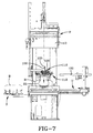
- Fig. 7 which is sequential to Fig. 6, the upper plate ring 50 is in the process of moving downwardly as a result of downward movement of the piston 60 of cylinder mechanism 55.
- bladder detector rod 120 moves vertically downwardly by gravity forces operative thereon with the lowering of upper plate ring 50.
- shaping pressure is introduced into the bladder 25 to effect its radial outward expansion within the tire band B.
- the clamp block 125 When the upper plate ring 50 reaches a predetermined position relative to the upper bead of the tire band B, the clamp block 125 is positioned in the sensing position of the proximity switch 128, the actuation of which controls the supply of operating media to piston 60 to stop and maintain piston 60 in the desired position of the upper plate ring 50 relative to the top bead of tire band B, as depicted in Fig. 8.
- the shoes 40 of loader 112 are retracted to release the upper bead of the tire band B.
- the loader 112 is then moved vertically and laterally to the position shown in Fig. 9.
- the press P is then closed in conventional fashion, with the upper mold section mounted within press head 13, brought into mating engagement with the lower mold section 12.
- full curing pressure is applied interiorly of the bladder 25, which, over a suitable time period, effects full cure of the tire band B in cooperation with the heat provided to the mold sections by the platens.
- the high-pressure curing fluid is scavenged from the bladder, and the press head is opened.
- Fig. 9 depicts the center mechanism 10 after cylinder mechanism 35 has moved lower bead ring 30 to its raised or extended position wherein piston 40 has moved from the solid-line position of Fig. 1 to the chain-line position 40'.
- cylinder mechanism 55 has extended bladder 25 to its stretched position by movement of piston 60 from the solid-line position of Fig. 1 to the chain-line position 60', which strips the bladder 25 from within the cured tire band B.
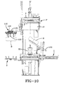
- Fig. 9 also shows an exemplary unloader, generally indicated by the letter U, having arms 130 that have been moved into position under the lower bead ring 30. Thereafter, lowering the lower bead ring 30 by moving piston 40 from the chain-line position 40' to the solid-line position 40 in Fig.
- the unloader U may then be manipulated as by tilting of the arms 130, as shown in Fig. 10, to effect discharge of the cured tire band B from the press. Withdrawal of the unloader U from the Fig. 10 position to the Fig. 5 position places the center mechanism 10 in condition for receiving a further uncured tire band B and a repetition of the operating cycle described herein.
Landscapes
- Engineering & Computer Science (AREA)
- Mechanical Engineering (AREA)
- Moulds For Moulding Plastics Or The Like (AREA)
- Heating, Cooling, Or Curing Plastics Or The Like In General (AREA)
Applications Claiming Priority (2)
| Application Number | Priority Date | Filing Date | Title |
|---|---|---|---|
| US09/178,842 US6416305B1 (en) | 1998-10-26 | 1998-10-26 | Tire curing press center mechanism |
| US178842 | 1998-10-26 |
Publications (2)
| Publication Number | Publication Date |
|---|---|
| EP0997254A2 true EP0997254A2 (fr) | 2000-05-03 |
| EP0997254A3 EP0997254A3 (fr) | 2001-01-03 |
Family
ID=22654137
Family Applications (1)
| Application Number | Title | Priority Date | Filing Date |
|---|---|---|---|
| EP99308432A Withdrawn EP0997254A3 (fr) | 1998-10-26 | 1999-10-26 | Mécanisme de centrage pour machine de vulcanisation de pneus |
Country Status (2)
| Country | Link |
|---|---|
| US (1) | US6416305B1 (fr) |
| EP (1) | EP0997254A3 (fr) |
Cited By (4)
| Publication number | Priority date | Publication date | Assignee | Title |
|---|---|---|---|---|
| US7607383B2 (en) | 2007-05-01 | 2009-10-27 | Nagel Robert W | System for backup rod seal for hydraulic cylinder |
| CN104908180A (zh) * | 2015-07-02 | 2015-09-16 | 江苏通用科技股份有限公司 | 拉伸高度可调的硫化胶囊 |
| CN105128231A (zh) * | 2015-09-24 | 2015-12-09 | 华澳轮胎设备科技(苏州)股份有限公司 | 用于轮胎硫化机加压机构的安全检测装置及方法 |
| CN115534377A (zh) * | 2022-11-01 | 2022-12-30 | 三角轮胎股份有限公司 | 全钢液压硫化机胶囊拉伸高度自动调整方法 |
Families Citing this family (7)
| Publication number | Priority date | Publication date | Assignee | Title |
|---|---|---|---|---|
| US7513763B1 (en) | 2007-06-04 | 2009-04-07 | Mcneil & Nrm, Inc. | Tire press center mechanism |
| JP5469361B2 (ja) * | 2009-04-10 | 2014-04-16 | 三菱重工マシナリーテクノロジー株式会社 | タイヤ加硫機の中心機構 |
| EP3313653B1 (fr) * | 2015-06-25 | 2020-05-06 | Bridgestone Americas Tire Operations, LLC | Anneaux de vessie pour moule de vulcanisation de pneumatique |
| CN105965926B (zh) * | 2016-05-23 | 2018-07-27 | 怡维怡橡胶研究院有限公司 | 一种轮胎成型方法 |
| EP3880279B1 (fr) * | 2018-11-13 | 2026-04-15 | Pulse NeedleFree Systems, LLC. | Ensemble de verrouillage à bille avec broche de retenue |
| CN109624154A (zh) * | 2019-02-14 | 2019-04-16 | 咸阳海龙密封复合材料有限公司 | 用于橡胶复合密封板的内置式大开档自动平板加热装置 |
| CN113580439B (zh) * | 2021-08-06 | 2023-05-26 | 青岛力沃液压机械有限公司 | 硫化机中心机构 |
Family Cites Families (18)
| Publication number | Priority date | Publication date | Assignee | Title |
|---|---|---|---|---|
| NL86381C (fr) | 1948-12-29 | |||
| US2699572A (en) | 1951-03-26 | 1955-01-18 | Mcneil Machine & Eng Co | Tire vulcanizing press with automatic bagging mechanism |
| US2730763A (en) | 1953-05-06 | 1956-01-17 | Nat Rubber Machinery Co | Tire curing press |
| NL95363C (fr) | 1953-09-29 | |||
| DE1065165B (de) | 1954-03-16 | 1959-09-10 | The Mc Neil Machine &. Engineering Company, Akron, Ohio (V. St. A.) | Presse zum Formen und Vu'kanisieren von Reifen |
| US2970342A (en) | 1957-10-17 | 1961-02-07 | Cleveland Trust Co | Vulcanizing press |
| GB1388055A (en) | 1972-06-09 | 1975-03-19 | Chodos Np | Two-section presses for vulcanizing tyre blanks |
| US3976409A (en) | 1974-11-07 | 1976-08-24 | Mcneil Corporation | Tire curing press center mechanism |
| IT1198209B (it) * | 1986-12-01 | 1988-12-21 | Pirelli | Miglioramenti alle presse di vulcanizzazione per pneumatici |
| US4863360A (en) * | 1988-01-15 | 1989-09-05 | Rogers Industrial Products | Bag control mechanism for tire press |
| JP2709099B2 (ja) * | 1988-10-17 | 1998-02-04 | 株式会社神戸製鋼所 | タイヤプレスにおけるスタンディングウエルポスト型中心機構 |
| JP2792707B2 (ja) | 1990-02-14 | 1998-09-03 | 株式会社神戸製鋼所 | タイヤ加硫機の中心機構におけるブラダ上部クランプ部の位置決め装置 |
| IT1251381B (it) * | 1991-08-30 | 1995-05-09 | Pirelli | Dispositivo di comando per camere di vulcanizzazione in presse di vulcanizzazione, e procedimento di comando attuato da detto dispositivo. |
| JP3238268B2 (ja) | 1994-02-24 | 2001-12-10 | 三菱重工業株式会社 | ブラダレスタイヤ加硫機の生タイヤ装着方法及び生タイヤ把持装置 |
| JPH08155961A (ja) | 1994-12-05 | 1996-06-18 | Kobe Steel Ltd | タイヤ加硫機用のローダ又はアンローダ |
| JP3221816B2 (ja) * | 1995-06-02 | 2001-10-22 | 株式会社神戸製鋼所 | タイヤ加硫機の中心機構 |
| JP2866027B2 (ja) * | 1995-06-06 | 1999-03-08 | 三菱重工業株式会社 | タイヤ加硫機用中心機構 |
| JPH09123171A (ja) | 1995-10-31 | 1997-05-13 | Kobe Steel Ltd | タイヤ加硫機の中心機構 |
-
1998
- 1998-10-26 US US09/178,842 patent/US6416305B1/en not_active Expired - Fee Related
-
1999
- 1999-10-26 EP EP99308432A patent/EP0997254A3/fr not_active Withdrawn
Cited By (5)
| Publication number | Priority date | Publication date | Assignee | Title |
|---|---|---|---|---|
| US7607383B2 (en) | 2007-05-01 | 2009-10-27 | Nagel Robert W | System for backup rod seal for hydraulic cylinder |
| CN104908180A (zh) * | 2015-07-02 | 2015-09-16 | 江苏通用科技股份有限公司 | 拉伸高度可调的硫化胶囊 |
| CN105128231A (zh) * | 2015-09-24 | 2015-12-09 | 华澳轮胎设备科技(苏州)股份有限公司 | 用于轮胎硫化机加压机构的安全检测装置及方法 |
| CN105128231B (zh) * | 2015-09-24 | 2017-06-20 | 华澳轮胎设备科技(苏州)股份有限公司 | 用于轮胎硫化机加压机构的安全检测装置及方法 |
| CN115534377A (zh) * | 2022-11-01 | 2022-12-30 | 三角轮胎股份有限公司 | 全钢液压硫化机胶囊拉伸高度自动调整方法 |
Also Published As
| Publication number | Publication date |
|---|---|
| EP0997254A3 (fr) | 2001-01-03 |
| US6416305B1 (en) | 2002-07-09 |
Similar Documents
| Publication | Publication Date | Title |
|---|---|---|
| CA1272567A (fr) | Methode de vulcanisation dans une presse de pneus | |
| US6416305B1 (en) | Tire curing press center mechanism | |
| EP0701894B2 (fr) | Moule à secteurs sans moyens de dégazage et procédé de vulcanisation de pneus utilisant ce moule | |
| US3976409A (en) | Tire curing press center mechanism | |
| US2559119A (en) | Tire curing apparatus and method | |
| EP1422036A1 (fr) | Procede et dispositif de vulcanisation de pneumatique | |
| US3260782A (en) | Press for shaping and curing pneumatic tires | |
| KR100252412B1 (ko) | 타이어프레스의센터기구 | |
| JPH01221207A (ja) | タイヤプレス | |
| KR910008054B1 (ko) | 타이어 프레스에서 직립 웰 포스트 형태(Standing Well Post Type)센터기구 | |
| US3298066A (en) | Tire presses | |
| TW397756B (en) | Central mechanism for tire vulcanizer | |
| US4400342A (en) | Bladderless, clampless curing | |
| US3134136A (en) | Tire carcass loading apparatus for tire curing press | |
| EP0578105A2 (fr) | Appareil à vulcaniser un pneumatique de véhicule routier | |
| US7513763B1 (en) | Tire press center mechanism | |
| KR100397749B1 (ko) | 타이어 가황 설비 | |
| US20090115103A1 (en) | Tire vulcanization method and tire vulcanization apparatus | |
| US2812545A (en) | Press for shaping and vulcanizing pneumatic tires | |
| US5102319A (en) | Hydraulic squeeze for tire curing press | |
| JP2001047438A (ja) | タイヤ加硫機の中心機構 | |
| US2978749A (en) | Tire manufacture | |
| JPH0780846A (ja) | タイヤ加硫設備 | |
| KR101376420B1 (ko) | 타이어 성형용 2 분할 금형 및 이 타이어 성형용 2 분할 금형을 사용한 타이어의 제조 방법 | |
| US4921412A (en) | Tire curing press |
Legal Events
| Date | Code | Title | Description |
|---|---|---|---|
| PUAI | Public reference made under article 153(3) epc to a published international application that has entered the european phase |
Free format text: ORIGINAL CODE: 0009012 |
|
| AK | Designated contracting states |
Kind code of ref document: A2 Designated state(s): DE FR GB |
|
| AX | Request for extension of the european patent |
Free format text: AL;LT;LV;MK;RO;SI |
|
| RIC1 | Information provided on ipc code assigned before grant |
Free format text: 7B 29C 35/02 A, 7B 30B 5/02 B, 7B 29D 30/06 B, 7B 29L 30:00 Z |
|
| PUAL | Search report despatched |
Free format text: ORIGINAL CODE: 0009013 |
|
| AK | Designated contracting states |
Kind code of ref document: A3 Designated state(s): AT BE CH CY DE DK ES FI FR GB GR IE IT LI LU MC NL PT SE |
|
| AX | Request for extension of the european patent |
Free format text: AL;LT;LV;MK;RO;SI |
|
| 17P | Request for examination filed |
Effective date: 20010514 |
|
| AKX | Designation fees paid |
Free format text: DE FR GB |
|
| 17Q | First examination report despatched |
Effective date: 20020830 |
|
| STAA | Information on the status of an ep patent application or granted ep patent |
Free format text: STATUS: THE APPLICATION IS DEEMED TO BE WITHDRAWN |
|
| 18D | Application deemed to be withdrawn |
Effective date: 20030110 |