EP0540078A2 - Unité d'association de gaine avec des boîtes de cassette vidéo - Google Patents
Unité d'association de gaine avec des boîtes de cassette vidéo Download PDFInfo
- Publication number
- EP0540078A2 EP0540078A2 EP92203115A EP92203115A EP0540078A2 EP 0540078 A2 EP0540078 A2 EP 0540078A2 EP 92203115 A EP92203115 A EP 92203115A EP 92203115 A EP92203115 A EP 92203115A EP 0540078 A2 EP0540078 A2 EP 0540078A2
- Authority
- EP
- European Patent Office
- Prior art keywords
- sleeve
- unit
- strip
- transparent sheet
- support member
- Prior art date
- Legal status (The legal status is an assumption and is not a legal conclusion. Google has not performed a legal analysis and makes no representation as to the accuracy of the status listed.)
- Withdrawn
Links
Images


Classifications
-
- G—PHYSICS
- G11—INFORMATION STORAGE
- G11B—INFORMATION STORAGE BASED ON RELATIVE MOVEMENT BETWEEN RECORD CARRIER AND TRANSDUCER
- G11B23/00—Record carriers not specific to the method of recording or reproducing; Accessories, e.g. containers, specially adapted for co-operation with the recording or reproducing apparatus ; Intermediate mediums; Apparatus or processes specially adapted for their manufacture
- G11B23/02—Containers; Storing means both adapted to cooperate with the recording or reproducing means
- G11B23/113—Apparatus or processes specially adapted for the manufacture of magazines or cassettes, e.g. initial loading into container
-
- B—PERFORMING OPERATIONS; TRANSPORTING
- B65—CONVEYING; PACKING; STORING; HANDLING THIN OR FILAMENTARY MATERIAL
- B65B—MACHINES, APPARATUS OR DEVICES FOR, OR METHODS OF, PACKAGING ARTICLES OR MATERIALS; UNPACKING
- B65B25/00—Packaging other articles presenting special problems
- B65B25/002—Packaging other articles presenting special problems packaging of information carriers, e.g. records, CD, DVD
-
- G—PHYSICS
- G11—INFORMATION STORAGE
- G11B—INFORMATION STORAGE BASED ON RELATIVE MOVEMENT BETWEEN RECORD CARRIER AND TRANSDUCER
- G11B23/00—Record carriers not specific to the method of recording or reproducing; Accessories, e.g. containers, specially adapted for co-operation with the recording or reproducing apparatus ; Intermediate mediums; Apparatus or processes specially adapted for their manufacture
- G11B23/02—Containers; Storing means both adapted to cooperate with the recording or reproducing means
- G11B23/023—Containers for magazines or cassettes
- G11B23/0233—Containers for a single cassette
Definitions
- This invention relates generally to videocassette or videotape cases, and more particularly to a unit for associating respective personalized sleeves with said cases.
- said cases are of book formation and comprise two half-shells of substantially rigid synthetic material hinged together at a spine.
- the outer surface of the case is covered by an extended transparent synthetic sheet welded to those edges of the half-shells which are opposing and parallel to the spine.
- Each of the devices of said documents basically comprises conveyor means driven with intermittent motion, on which the cases are laid open with their concavity facing upwards and with their spine positioned transversely to the direction of advancement of the cases, an overlying unit arranged to grip and position the cases when said conveyor means are stationary, and a horizontal insertion plate structure for the sleeves which is positioned to the side of said conveyor means and gripping unit.
- said gripping unit arranges the two half-shells of the case at an opening angle greater than 180 degrees, while the corresponding transparent sheet is flexed in the opposite direction.
- the sleeve insertion plate structure of the two aforesaid documents in both cases it consists of two side-by-side coplanar plates driven with reciprocating towards and away from each other, and arranged on a slide which slides perpendicular to said movement and to the direction of advancement of the cases.
- the said plates have the front portions of their respective outer longitudinal edges bent inwards through substantially 180 degrees to form two seats in which the opposing transverse edges of the sleeve are guided and slide.
- the two plates are arranged to occupy a rearward position in which they are spaced apart to receive a sleeve, after which they move together for insertion into the space between the case and the transparent sheet, then after insertion into said space they again widen out to position the sleeve in this space.
- the need to insert the plate structure between the case and sheet means that this latter must have a width less than the distance between the welding lines of said sheet, to the detriment of appearance.
- the main object of the present invention is to provide a unit for associating sleeves with respective cases which totally obviates the aforesaid problems.
- the idea on which the invention is based is to prearrange the sleeve in such a manner that it can be inserted by itself into the space between the case and transparent sheet, ie without the need to insert any other member or element into this space.
- a construction suitable for the purpose comprises a support member for the sleeve, on which this latter rests via its opposing lateral edges and via its central strip which is parallel to these latter, and an overlying vertically slidable member arranged to occupy a raised position in which it enables the sleeve substantially spread out on said support member to be loaded, and a lowered position in which it rests on those two sleeve portions located on one and the other side of said central strip in such a manner as to flex these latter upwards, with simultaneous mutual approach of the opposing edges of the sleeve.
- the support member can consist for example of three mutually parallel side-by-side horizontal strips, of which the central one is preferably positioned at a higher level than that of the lateral strips, said vertically slidable member consisting for example of two coplanar side-by-side horizontal bars parallel to each other and to said strips. All the objects of the invention are attained by the aforesaid means.
- sleeves can be used having a width practically equal to the distance between the lines along which the transparent sheet is welded to the case.
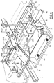
- Figure 1 is a latero-rear perspective view of the invention with parts cut away.
- Figure 2 is a side view to a greater scale, with parts cut away.
- Figure 3 is a section on the line III-III of Figure 2 to a greater scale.
- the unit of the invention is shown associated with a device of the type described in the documents cited in the introduction, but this must in no way be considered as limiting its application thereto, in that the invention is suitable for any device or apparatus able to position videocassette cases ready for receiving respective sleeves, as shown in the figure.
- Said figures show a usual horizontal conveyor line indicated by 1 and shown schematically for the aforesaid reasons, it being driven with intermittent motion so as to position the cases 2 one after another in front of the unit of the invention.
- said surfaces 3 comprise respective suckers 200 for gripping the sheet 20, and with which there correspond two overlying vertically mobile suckers 210 for gripping and raising the spine 21.
- Two inclined plates 220 converging towards said two upper suckers 210 cooperate with these latter to maintain the two half-shells 22 of the case equally inclined when the spine 21 has been raised ( Figure 1).
- the case 2 is opened by more than 180 degrees and the sheet 20 is flexed in the opposite direction, so that a space for the insertion of the sleeve 4 is defined between the case and sheet.
- the loading unit of the invention comprises two coplanar horizontal supports 6 of right-angled cross-section which are parallel to each other and perpendicular to the conveying line 1.
- the two supports 6 are provided with clamps 66 for adjusting their distance apart and each comprises, extending along its entire length, a downwardly inclined internal horizontal ledge 7 with its longitudinal edge free.
- each support 6 Between the upper longitudinal edge of each support 6 and the respective ledge 7 a seat of obtuse-angled right cross-section is formed for supporting and receiving the corresponding lateral edge of the sleeves 4.
- the facing surfaces of the vertical edges of the two supports 6 are spaced apart (with the possibility of adjustment, as stated) by a distance practically equal to the distance between the lines along which the transparent sheet 20 is welded to the case 2, or in other words to the width of the sleeve 4 when completely extended.
- a horizontal strip 77 is positioned centrally between said two ledges 7 and parallel to these latter, at a level higher than that of the two ledges but lower than that of the spine 21 when in its raised position.
- the strip 77 is fixed to project rearwards over the surface 3, and below it in a position between the two ledges 7 there is a vertical transverse pusher plate 8 operated by a cylinder-piston unit 80.
- the plate 8 comprises two vertically extending opposing elongate recesses 88, externally to which the corresponding portions of the plate 8 are bent doubly forwards in the two opposing directions.
- each bar 800 and the corresponding recess 88 lie in a common vertical plane lying between the vertical planes passing through the mutually facing edges of said strip 77 and the respective ledge 7. The reason for this will be apparent hereinafter.
- said pair of bars 800 is supported by a fork-shaped frame 90 which is made to slide vertically by a respective cylinder-piston unit 99. It should also be noted that the length of said strips 77, ledges 7 and bars 800 is of the same order of magnitude as the length of the sleeve 4 ( Figure 2).
- the described loading unit operates as follows. Before a case 2 halts and is positioned as heretofore described (see Figures 1, 3), the bars 800 are in their raised position whereas the plate 8 and stop member 5 are in their retracted position.
- a suitable loading device (not shown because of usual type) transfers a sleeve 4 from a respective storage region, such as that indicated for example by dotted lines to the right of Figure 1, onto the strip 77 of the unit and consequently onto the ledges 7.
- the two lateral edges of the sleeve are spaced apart by a distance substantially equal to the horizontal distance between the lines along which the transparent sheet 20 is welded to the open case 2.
- the bars 800 receive the enabling signal to descend as shown by full lines in all the accompanying figures.
- the two sleeve portions lying on one and the other side of the strip 77 assume a curvature which is the opposite of that determined by said strip 77, so that the two lateral edges of the sleeve 4 move towards each other to a (horizontal) distance apart which is less than that between the lines along which the sheet 20 is welded to the open case 2.
- the sleeve assumes an omega-shaped configuration.
- the path of downward travel of the bars 800 is such as to maintain the vertical extension of the transverse outline of the doubly flexed sleeve within the outline of the mouth of the space formed between the case 2 and sheet 20.
- the cylinder-piston unit 80 receives the enabling signal to advance the plate 8, with simultaneous insertion of the sleeve between the case 2 and the transparent sheet 20.
- the sleeve 4 spreads out on abandoning the bars 800, after which the entire assembly is repositioned as previously, for loading a further sleeve and for awaiting the arrival of the next case.
- a channel-shaped body can be provided instead of the two bars 800.
Landscapes
- Engineering & Computer Science (AREA)
- Mechanical Engineering (AREA)
- Packaging Frangible Articles (AREA)
- Packaging Of Annular Or Rod-Shaped Articles, Wearing Apparel, Cassettes, Or The Like (AREA)
Applications Claiming Priority (2)
| Application Number | Priority Date | Filing Date | Title |
|---|---|---|---|
| ITRE910072A IT1252751B (it) | 1991-10-30 | 1991-10-30 | Gruppo per associare locandine a scatole per videocassette. |
| ITRE910072 | 1991-10-30 |
Publications (2)
| Publication Number | Publication Date |
|---|---|
| EP0540078A2 true EP0540078A2 (fr) | 1993-05-05 |
| EP0540078A3 EP0540078A3 (en) | 1994-06-22 |
Family
ID=11398081
Family Applications (1)
| Application Number | Title | Priority Date | Filing Date |
|---|---|---|---|
| EP19920203115 Withdrawn EP0540078A3 (en) | 1991-10-30 | 1992-10-09 | Unit for associating sleeves with videocassette cases |
Country Status (2)
| Country | Link |
|---|---|
| EP (1) | EP0540078A3 (fr) |
| IT (1) | IT1252751B (fr) |
Family Cites Families (5)
| Publication number | Priority date | Publication date | Assignee | Title |
|---|---|---|---|---|
| US4555290A (en) * | 1984-04-19 | 1985-11-26 | Blair Industries, Inc. | Method of making cassette holders |
| US4718550A (en) * | 1986-10-24 | 1988-01-12 | Johnson Breck J | Thermoformed composite cassette album |
| FR2646374A1 (fr) * | 1989-04-28 | 1990-11-02 | Biotti Jean | Chaine automatique de fabrication de boitiers cassettes en plastique thermoforme et carton |
| IT1234154B (it) * | 1989-06-19 | 1992-05-04 | Sacma Plastdi Sacchini Enzo & | Dispostivo per associare locandine a cassette per videonastri |
| US5038462A (en) * | 1989-09-08 | 1991-08-13 | Dorner Mfg. Corp. | Apparatus for assembling articles from two halves such as video cassette containers |
-
1991
- 1991-10-30 IT ITRE910072A patent/IT1252751B/it active IP Right Grant
-
1992
- 1992-10-09 EP EP19920203115 patent/EP0540078A3/en not_active Withdrawn
Also Published As
| Publication number | Publication date |
|---|---|
| ITRE910072A0 (it) | 1991-10-30 |
| EP0540078A3 (en) | 1994-06-22 |
| ITRE910072A1 (it) | 1993-04-30 |
| IT1252751B (it) | 1995-06-28 |
Similar Documents
| Publication | Publication Date | Title |
|---|---|---|
| US5457941A (en) | Envelope stuffing machine | |
| CA2080513C (fr) | Appareil de remplissage d'enveloppe avec plateau reglable pour traiter divers types d'enveloppes | |
| EP0623535B1 (fr) | Dispositif de transport pour masses solides | |
| EP0989060B1 (fr) | Procédé et machine pour grouper des emballages du type blister et pour transporter ces groupes | |
| EP0464002A1 (fr) | Dispositif pour former et insérer une pile d'emballages de type blister dans un carton | |
| US4031585A (en) | Binding of perforated sheets | |
| EP0713448A1 (fr) | Appareil de reliure automatique | |
| NO309031B1 (no) | Maskin til fremstilling av en madrassbane | |
| US4803764A (en) | Apparatus for manufacturing a spacer frame for insulating glass | |
| US3889309A (en) | Machines for binding packets of perforated sheets | |
| US4318685A (en) | Insert bander | |
| EP0540078A2 (fr) | Unité d'association de gaine avec des boîtes de cassette vidéo | |
| AU619499B2 (en) | An automatic bookbinding machine | |
| US3588991A (en) | Forming and attaching top stops to fastener chains | |
| EP0603977B1 (fr) | Dispositif d'alimentation de flans | |
| US20070186508A1 (en) | Cartoning machine | |
| US4663914A (en) | Wrapping machine for applying a web to one or more articles to form a package | |
| KR100411801B1 (ko) | 슬라이딩 사입식 자동 리필 팩커 및 이를 이용한 자동리필 팩킹 방법 | |
| TW356574B (en) | Device for separation and conveying of thread-guiding frame | |
| KR850008427A (ko) | 핵연료 집합체 그리드에 대한 헤어핀 스프링 위치 결정 장치 | |
| CA2294720A1 (fr) | Pince pour maintenir des objets plans | |
| EP0949149B1 (fr) | Procédé et dispositif pour couper des bandes de cerclage de piles ou d' emballages d'étiquettes ou de feuilles | |
| EP0575019B1 (fr) | machine à relier | |
| US1855638A (en) | Machine for feeding inserts | |
| JPS5941694Y2 (ja) | スライドフアスナ−チエ−ンのスペ−ス作成装置 |
Legal Events
| Date | Code | Title | Description |
|---|---|---|---|
| PUAI | Public reference made under article 153(3) epc to a published international application that has entered the european phase |
Free format text: ORIGINAL CODE: 0009012 |
|
| AK | Designated contracting states |
Kind code of ref document: A2 Designated state(s): AT BE CH DE DK ES FR GB GR IE IT LI LU MC NL PT SE |
|
| PUAL | Search report despatched |
Free format text: ORIGINAL CODE: 0009013 |
|
| AK | Designated contracting states |
Kind code of ref document: A3 Designated state(s): AT BE CH DE DK ES FR GB GR IE IT LI LU MC NL PT SE |
|
| 18D | Application deemed to be withdrawn |
Effective date: 19941223 |