EP0540834B2 - Méthode et dispositif pour couper des structures sous-marines - Google Patents
Méthode et dispositif pour couper des structures sous-marines Download PDFInfo
- Publication number
- EP0540834B2 EP0540834B2 EP19920113871 EP92113871A EP0540834B2 EP 0540834 B2 EP0540834 B2 EP 0540834B2 EP 19920113871 EP19920113871 EP 19920113871 EP 92113871 A EP92113871 A EP 92113871A EP 0540834 B2 EP0540834 B2 EP 0540834B2
- Authority
- EP
- European Patent Office
- Prior art keywords
- cutting
- anchorage
- frame
- cradle
- turn
- Prior art date
- Legal status (The legal status is an assumption and is not a legal conclusion. Google has not performed a legal analysis and makes no representation as to the accuracy of the status listed.)
- Expired - Lifetime
Links
Images


Classifications
-
- E—FIXED CONSTRUCTIONS
- E02—HYDRAULIC ENGINEERING; FOUNDATIONS; SOIL SHIFTING
- E02D—FOUNDATIONS; EXCAVATIONS; EMBANKMENTS; UNDERGROUND OR UNDERWATER STRUCTURES
- E02D9/00—Removing sheet piles bulkheads, piles, mould-pipes or other moulds or parts thereof
- E02D9/04—Removing sheet piles bulkheads, piles, mould-pipes or other moulds or parts thereof by cutting-off under water
-
- B—PERFORMING OPERATIONS; TRANSPORTING
- B23—MACHINE TOOLS; METAL-WORKING NOT OTHERWISE PROVIDED FOR
- B23D—PLANING; SLOTTING; SHEARING; BROACHING; SAWING; FILING; SCRAPING; LIKE OPERATIONS FOR WORKING METAL BY REMOVING MATERIAL, NOT OTHERWISE PROVIDED FOR
- B23D53/00—Machines or devices for sawing with strap saw-blades which are effectively endless in use, e.g. for contour cutting
- B23D53/003—Machines or devices for sawing with strap saw-blades which are effectively endless in use, e.g. for contour cutting with means to attach the sawing device to the workpiece
-
- B—PERFORMING OPERATIONS; TRANSPORTING
- B23—MACHINE TOOLS; METAL-WORKING NOT OTHERWISE PROVIDED FOR
- B23D—PLANING; SLOTTING; SHEARING; BROACHING; SAWING; FILING; SCRAPING; LIKE OPERATIONS FOR WORKING METAL BY REMOVING MATERIAL, NOT OTHERWISE PROVIDED FOR
- B23D53/00—Machines or devices for sawing with strap saw-blades which are effectively endless in use, e.g. for contour cutting
- B23D53/04—Machines or devices for sawing with strap saw-blades which are effectively endless in use, e.g. for contour cutting with the wheels carrying the strap mounted shiftably or swingingly, i.e. during sawing, other than merely for adjustment
-
- B—PERFORMING OPERATIONS; TRANSPORTING
- B23—MACHINE TOOLS; METAL-WORKING NOT OTHERWISE PROVIDED FOR
- B23D—PLANING; SLOTTING; SHEARING; BROACHING; SAWING; FILING; SCRAPING; LIKE OPERATIONS FOR WORKING METAL BY REMOVING MATERIAL, NOT OTHERWISE PROVIDED FOR
- B23D57/00—Sawing machines or sawing devices not covered by one of the preceding groups B23D45/00 - B23D55/00
- B23D57/0084—Sawing machines or sawing devices not covered by one of the preceding groups B23D45/00 - B23D55/00 specially adapted for sawing under water or at places accessible with difficulty
-
- B—PERFORMING OPERATIONS; TRANSPORTING
- B28—WORKING CEMENT, CLAY, OR STONE
- B28D—WORKING STONE OR STONE-LIKE MATERIALS
- B28D1/00—Working stone or stone-like materials, e.g. brick, concrete or glass, not provided for elsewhere; Machines, devices, tools therefor
- B28D1/02—Working stone or stone-like materials, e.g. brick, concrete or glass, not provided for elsewhere; Machines, devices, tools therefor by sawing
- B28D1/08—Working stone or stone-like materials, e.g. brick, concrete or glass, not provided for elsewhere; Machines, devices, tools therefor by sawing with saw-blades of endless cutter-type, e.g. chain saws, i.e. saw chains, strap saws
- B28D1/088—Sawing in situ, e.g. stones from rocks, grooves in walls
-
- B—PERFORMING OPERATIONS; TRANSPORTING
- B63—SHIPS OR OTHER WATERBORNE VESSELS; RELATED EQUIPMENT
- B63C—LAUNCHING, HAULING-OUT, OR DRY-DOCKING OF VESSELS; LIFE-SAVING IN WATER; EQUIPMENT FOR DWELLING OR WORKING UNDER WATER; MEANS FOR SALVAGING OR SEARCHING FOR UNDERWATER OBJECTS
- B63C11/00—Equipment for dwelling or working underwater; Means for searching for underwater objects
- B63C11/34—Diving chambers with mechanical link, e.g. cable, to a base
- B63C11/36—Diving chambers with mechanical link, e.g. cable, to a base of closed type
- B63C11/40—Diving chambers with mechanical link, e.g. cable, to a base of closed type adapted to specific work
-
- E—FIXED CONSTRUCTIONS
- E02—HYDRAULIC ENGINEERING; FOUNDATIONS; SOIL SHIFTING
- E02B—HYDRAULIC ENGINEERING
- E02B17/00—Artificial islands mounted on piles or like supports, e.g. platforms on raisable legs or offshore constructions; Construction methods therefor
- E02B2017/0052—Removal or dismantling of offshore structures from their offshore location
-
- Y—GENERAL TAGGING OF NEW TECHNOLOGICAL DEVELOPMENTS; GENERAL TAGGING OF CROSS-SECTIONAL TECHNOLOGIES SPANNING OVER SEVERAL SECTIONS OF THE IPC; TECHNICAL SUBJECTS COVERED BY FORMER USPC CROSS-REFERENCE ART COLLECTIONS [XRACs] AND DIGESTS
- Y10—TECHNICAL SUBJECTS COVERED BY FORMER USPC
- Y10T—TECHNICAL SUBJECTS COVERED BY FORMER US CLASSIFICATION
- Y10T83/00—Cutting
- Y10T83/929—Tool or tool with support
- Y10T83/9317—Endless band or belt type
Definitions
- the invention relates to a method and a device for cutting underwater structures and particularly for cutting underwater structures such as, for example, ducts, pillars supporting offshore platforms, or the like and which are made mostly of steel or other metals or of mixed materials, such as steel or other metals and cement, or the like.
- said structures are cut manually by teams of underwater workmen who operate directly on the spot with suitable tools such as, for example, thermal lances, electrodes for underwater cutting, grinders, pipe-cutters, etc.
- suitable tools such as, for example, thermal lances, electrodes for underwater cutting, grinders, pipe-cutters, etc.
- these operations are tiresome, expensive and involve considerable fatigue and risks for the operating personnel.
- the high costs of these operations are determined by the considerable duration of the cutting operations, by the necessity to engage highly-specialized operating personnel in very dangerous conditions, and by the resulting necessity to provide adequate assistance means with a corresponding number of auxiliary operators.
- the operating conditions become even more difficult when the structures to be cut are of the composite type such as, for example, in case of elements constituted by concentric steel pipes whose interspaces are filled with concrete or cement. In effect, in these instances, the cutting through the interspace cannot be ensured even by the most sophisticated tools, so that the intermediate layer of cement must be broken down before acting on the inner pipes.
- the duration of these operations may last
- the invention is based on the problem of providing a method and a device for cutting underwater structures, which, thanks to a construction as simple and economical as possible, permit to carry out the cutting operations with extreme ease and rapidity, minimizing the risks and costs.
- the invention solves said problem by a method defined in claim 1 and the device defined in claim 3.
- the feed of the cutting means is effected by the upward push of water on a body of lower specific gravity, while the push for feeding the cutting means against the structure is adjusted to the optimum value by varying the upward push, i.e. the specific gravity of said body.
- the method and device according to the invention permit to achieve undoubted functional advantages.
- the use of specialized underwater personnel is only required, if desired, in the anchorage, recovery and check steps in the course of the work. These steps require a very limited number of underwater operators.
- the cutting step is controlled directly from the surface. This eliminates completely the disadvantages of the presently-used systems, thus minimizing the risks of the operating personnel and reducing considerably the costs of the operations.
- the cutting operations do not suffer substantially from the meteo-marine conditions and can be carried out uninterruptedly throughout the 24 hours of the day, thus increasing the productivity and reducing the costs furthermore.
- the cold-cutting means used by the invention permit to obtain much shorter working periods and ensure the utmost safety when working on structures in dangerous environments such as, for example, in the presence of liquid or gaseous hydrocarbons or flammable compounds.
- the particular construction of the device enables the execution of cutting operations at any depth even exceeding the possibility of use of underwater operators, because the anchorage, recovery and check steps may be easily effected by means of submersible units or by remotely-controlled vehicles.
- the invention also relates to other characteristics which further improve said device and which form the subject of the subclaims.
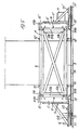
- the device shown in the figures is constructed in the form of a cutting frame T of rectangular or square configuration which is anchored directly in straddling relation to the element to be cut S of any structure, for example, around a pillar of an offshore platform.
- the cutting line is displaceable along a cutting plane parallel to one of the longer sides of the cutting frame T.
- the cutting frame T In order to effect a cut through the pillar along a horizontal plane, the cutting frame T, therefore, is arranged flatwise with the cutting line lying on said plane.
- the actuation and feed of the motors of the cutting frame is effected thanks to control and feed units U arranged at the surface, for example, on suitable auxiliary watercraft and which are connected by umbilical cables C to said cutting frame T.
- the motors of the cutting frame T may be of any type, namely of electric, hydraulic, pneumatic type, or the like.
- the cutting frame T is formed by a quadrilateral framework two opposite sides of which constitute slide guides 2,2' orientated in the cutting direction, parallelly to each other and to the cutting plane.
- Each guide 2,2' comprises two guide tubes 102,102' which are perfectly aligned to each other perpendicularly to the cutting plane.
- the free ends of the guides 2,2' are rigidly connected to each other, at one side by a transverse member 3 connecting the two guides and stationarily secured thereto, and at the opposite side by head members 5.
- the stationary transverse member 3 and the head members 5 constitute simultaneously the limit stops for the guides 2,2'.
- the side of the framework which is opposite to the stationary transverse one 3 is constructed as an openable gate-like member.
- transverse member 4 which is removably secured to the corresponding head members 5 of the guides 2,2'.
- hinge-type locking members 6 comprising two bushes 106 which are secured to the head members 5 of the guides in spaced apart relation, and a tube member 206 co-axially arranged therebetween.
- the hinge spindle is formed by an extractable bolt 306 provided with a radial grasping extension 406 at an end thereof, preferably at the upper end.
- the transverse member 3, fixedly secured to the guides 2,2', is provided intermediately with an anchorage cradle 7 which forms a V-shaped accommodation seat in the cutting direction so as to match different shapes and diameters of the element S of the structure to be cut.
- an anchorage cradle 7 Associated with the anchorage cradle 7 is a means 8 for tightening the element S of the structure against it.
- Said means can girdle the element S of the structure on the side away from the cradle 7 and in the illustrated embodiment it is formed by a metallic cable which is passed at least twice around the portion of the element S that is away from the anchoring cradle 7 and at planes which are spaced apart and parallel to the cutting plane, preferably coincident with the respective sides of the framework, in this instance with the upper side and lower side thereof.
- the free ends of the cable are fixedly connected to the opposite peripheral edges of the stationary transverse member 3 at points 10 thereon which are aligned to each other perpendicularly with respect to the cutting plane and which are arranged intermediately between one of the guides 2 and the corresponding side of the anchorage cradle 7, while it is turned round to points 10' which are symmetrically opposite with respect to the central axis which is directed in the cutting direction, between the opposite guide 2' and the facing side of the anchorage cradle 7.
- the connection of the ends of the cable is effected with the intermediary of adjustable tension means 9 such as, for example, turnbuckles or the like.
- a cutting unit Movably mounted on the slide guides 2,2' is a cutting unit which is formed by two slides 11,11' each comprising two tubular slide members 12 which are engaged on the respective guide tubes 102,102' and are connected rigidly to each other.
- the sliding movement of the slide members 12 is ensured thanks to an inner lining of suitable material such as, for example, teflon or the like.
- Each slide 11,11' carries a turn-round pulley 13,13' which is rotatable about an axis perpendicular to the cutting plane and having mounted thereon an endless cutting cable 14, for example, of the diamond-coated beads type and capable contemporarily both of cutting metallic materials and other materials such as cement, concrete, stone, or the like.
- the turn-round pulleys 13,13' are arranged in an outwardly-protruding position, both laterally and vertically beyond the corresponding sides of the slides 11, 11'.
- This permits to cut easily flush with the supporting bottom, for example, a vertical pillar such as that shown in the drawings with no need, unlike what has been effected heretofore, to dig a trench around the base of the pillar to permit the personnel to work.
- the two turn-round pulleys 13,13' are mounted on shelves 111,111' of the slides 11,11', protruding outwards from the outer sides thereof.
- One of the two turn-round pulleys 13' is mounted stationarily and is associated with an actuating motor M.
- the other turn-round pulley 13 is mounted so as to be displaceable crosswise to the cutting direction towards and away from the powered pulley 13', so as to allow the cutting cable 14 to be mounted and made taut, said pulley 13 being associated with removable means 113 to lock it in position.
- the displaceable turn-round pulley 13 has also associated therewith means for its predetermined positioning in an approaching position and in one or more tensioning positions of the cutting cable 14.
- the turn-round pulley 13 is rotatably mounted on a supporting plate 213.
- the plate 213 is secured to the shelf 111 by means of through-bolts 113 engaged in slots 211 in the shelf 111.
- the plate 213 and bracket 111 have each two rows of at least two holes 311,313 therethrough in registry with each other and receiving a removable locking pin 15. This permit to effect with great rapidity the operations of mounting and tensioning the cutting cable 14.
- each slide 11 On the head member outer side facing towards the structural element S to be cut, each slide 11 is connected to a traction cable 16.
- the traction cable 16 extends exteriorly along the respective guides 2,2' and is turned round parallelly to the rear side of the stationary transverse member 3 by means of an idle turn-round pulley 17 which is rotatably mounted about an axis perpendicular to the cutting plane on a rear bracket 103 of the transverse member 3.
- a further shelf 203 mounting two additional turn-round pulleys 18 for directing the respective traction cable 16 in a vertical direction upwards.
- the turn-round pulleys 18 are comparatively close to each other and, preferably, they are mounted on a common bracket 19 which can oscillate about a horizontal axis parallel to the transverse member 3.
- the vertically turned round and near branches of the traction cable 16 are connected at their ends to a variable-buoyancy body 20, such as an inflatable balloon.
- a variable-buoyancy body 20 such as an inflatable balloon.
- the buoyancy push thereon can be varied, thus obtaining the possibility of adjusting very simply the thrust of the cutting cable 14 against the element S to be cut in accordance with the power of the cutting unit and the type of materials constituting the structure.
- the arrangement of the vertically turn-round pulleys 18 on a common oscillatable bracket 19 permits the execution of cuts along planes of any inclination with respect to the horizontal plane, including the vertical direction.
- the application of the device to a structural element S to be cut is extremely rapid and simple.
- the cutting frame is straddled on the element S to be cut by removing the transverse removable member 4 and the cutting cable 14.
- the cutting cable 14 and removable transverse member 4 are mounted.
- the pre-established required amount of air or gas is fed into the balloon 20. From the above, it becomes apparent that said operations can be carried out easily and quickly by a reduced number of workers. At this stage, the underwater local operations have been completed, and the cutting stage may be controlled safely and with great ease from the surface.
- the only actuating motor to be fed adequately is, in effect, the one which is associated with the powered turn-round pulley 13' and is suitably connected to the control and feed means A at the surface.
- the pillars of the structure are formed by concentric steel tubes which are separated by an interspace which is filled with either cement or concrete.
- the cable 14 of diamond-coated beads is displaced transversely against and through the pillar S with a constant and suitably calibrated force and it cuts indifferently and with no problems both the metallic and the concrete portions without requiring any interruptions for using either manually or automatically other types of tools.
Landscapes
- Engineering & Computer Science (AREA)
- Mechanical Engineering (AREA)
- Mining & Mineral Resources (AREA)
- Paleontology (AREA)
- Life Sciences & Earth Sciences (AREA)
- General Life Sciences & Earth Sciences (AREA)
- Ocean & Marine Engineering (AREA)
- Civil Engineering (AREA)
- General Engineering & Computer Science (AREA)
- Structural Engineering (AREA)
- Processing Of Stones Or Stones Resemblance Materials (AREA)
- Placing Or Removing Of Piles Or Sheet Piles, Or Accessories Thereof (AREA)
- Earth Drilling (AREA)
Claims (13)
- Méthode pour couper des structures sous-marines par une étape télécommandée comprenant la mise en action automatique depuis la surface de moyens de coupe et l'alimentation automatique dans la direction de coupe le long du plan de coupe, depuis la position de non interférence avec la structure vers et à travers celle-ci, l'exécution de la coupe et l'arrêt automatique de l'alimentation et de la mise en action des moyens de coupe, caractérisée en ce que :une étape sous-marine locale comprenant, d'une part, le positionnement et l'ancrage à la structure (S) devant être coupée, dans la zone de coupe de celle-ci, des moyens de coupe comprenant un cadre de coupe supportant une unité de coupe montée sur ce dernier, utilisant un câble en diamant sans fin en boucle fermée (11, 11', 12, 13, 13', 14, M) disposé de manière à éviter les interférences avec la structure (S) pendant ledit ancrage par lequel la structure (S) est située complètement à l'extérieur du câble (14) en boucle fermée, orientée de manière à ce que sa ligne de coupe coïncide avec le plan de coupe souhaité, et, d'autre part, déplaçant l'unité de coupe (11, 11', 12, 13, 13', M) par rapport à la structure (S) pour en effectuer la coupe ; et une étape sous-marine locale finale similaire à la première étape, comprenant la récupération desdits moyens de coupe (T).
- Méthode selon la revendication 1, caractérisée en ce que le mouvement d'alimentation des moyens de coupe (T) est actionné par la poussée vers le haut de l'eau sur un corps (20) de gravité spécifique inférieure, tandis que la poussée pour alimenter les moyens de coupe (T) contre la structure (S) est ajustée à sa valeur optimale en faisant varier la poussée vers le haut, c'est-à-dire la gravité spécifique dudit corps (20).
- Dispositif destiné à mettre en oeuvre la méthode selon la revendication 1 ou 2, comprenant une unité de coupe commandée par moteur (11, 11', 12, 13, 13', 14, M) pouvant être déplacée dans la direction de coupe parallèlement au plan de coupe sur un cadre de coupe (T), de manière à déplacer l'unité de coupe (14) d'une position initiale de non interférence avec la structure (S) vers une position finale dans laquelle ladite unité de coupe (14) a été déplacée vers le côté opposé de la structure (S) devant être coupée en passant à travers celle-ci le long du plan de coupe prédéterminé, caractérisé en ce qu'il comprend :un cadre de coupe sous-marin (T) présentant des moyens amovibles (7, 8) pour le positionnement et l'ancrage à la structure (S) devant être coupée selon le plan de coupe prédéterminé ;une unité de coupe comprenant un câble en diamant sans fin en boucle fermée (11, 11', 12, 13, 13', 14, M) monté sur ledit cadre de coupe (T) et pouvant être déplacé d'une position dans laquelle le câble (14) est situé complètement à l'extérieur de la structure (S), vers une position de fonctionnement dans laquelle lesdits outils de coupe sont déplacés le long du plan de coupe contre et à travers la structure (S) ;une unité de réglage sous-marine (20) destinée à déplacer dans la direction de coupe ladite unité de coupe qui est supportée par le cadre de coupe sous-marin (T) ;des moyens de commande et de mise en oeuvre télécommandés (A,C) pour l'unité de coupe (11, 11', 12, 12', 13, 13', M, 14) et éventuellement pour l'unité de traction (20), disposés à la surface.
- Dispositif selon l'une des revendications précédentes, caractérisé en ce que le cadre de coupe (T) comprend un berceau d'ancrage (7) qui est ouvert vers le côté interne du cadre de coupe (T) et qui présente de manière associée des moyens amovibles (8) destinés à verrouiller la structure (S) contre le berceau d'ancrage (7) ; une paire de glissières de guidage coulissantes (2, 2') munies de dispositifs d'arrêt de limite (3, 5) en leurs extrémités, lesdites glissières de guidage (2, 2') étant dirigées dans la direction de coupe parallèlement l'une à l'autre et parallèlement au plan de coupe et étant espacées l'une de l'autre de manière transversale par rapport à la direction de coupe et depuis le côté respectif du berceau d'ancrage (7), et chacune desdites glissières de guidage (2, 2') supporte de manière coulissante un coulisseau (11, 11') pour une poulie pivotante respective (13, 13'), lesdites poulies pivotantes (13, 13') pouvant tourner autour d'un axe perpendiculaire au plan de coupe et s'étendant essentiellement sur ledit plan de coupe, et au moins l'une desdites poulies pivotantes (13') étant commandée par moteur (M), tandis que le câble de coupe (14) qui est de configuration sans fin, est monté sur les deux poulies pivotantes (13, 13').
- Dispositif selon la revendication 4, caractérisé en ce que le cadre de coupe (T) est construit comme une structure rectangulaire et le berceau d'ancrage (7) est disposé à l'intérieur de celui-ci, dans la zone à une extrémité des glissières de guidage (2, 2'), de manière centrale entre celles-ci, et est ouvert vers les extrémités opposées des glissières de guidage (2, 2') qui peuvent être reliées l'une à l'autre par un élément de traverse en forme de porte amovible (4) par exemple, au moyen de charnières (6) présentant une tige de charnière extractible (306), de sorte que le cadre de coupe (T) peut être ouvert pour ancrage en enjambant la structure (S) devant être coupée.
- Dispositif selon la revendication 4 ou 5, caractérisé en ce qu'une poulie pivotante (13') pour le câble de coupe (14) est fixée de manière stationnaire sur le coulisseau associé (11') et est commandée par un moteur (M) également supporté par le coulisseau (11'), tandis que l'autre poulie pivotante (13) est montée sur l'autre coulisseau (11) de manière à pouvoir tourner librement et se déplacer d'une position plus proche de la poulie pivotante commandée par moteur (13') vers une position plus éloignée de celle-ci dans laquelle le câble de coupe (14) est sous tension, des moyens amovibles (113) étant fournis pour verrouiller la poulie pivotante pouvant se déplacer (13) en position.
- Dispositif selon la revendication 6, caractérisé en ce que la poulie pivotante pouvant se déplacer (13) est également associée à des moyens de positionnement prédéterminé qui peuvent être verrouillés temporairement (111, 213, 311, 312, 15) dans la position la plus proche et dans la position de tension du câble.
- Dispositif selon la revendication 7, caractérisé en ce que la poulie pouvant être déplacée (13) est montée sur une plaque (213) qui est retenue de manière à pouvoir coulisser transversalement vers la direction de coupe et à être verrouillée en position sur un socle (111) qui est solidaire du coulisseau (11), tandis que les moyens qui peuvent être verrouillés temporairement pour le positionnement prédéterminé consistent en rangées de trous coïncidantes (312, 311) dans la plaque coulissante (213) et dans le socle (111) et en une cheville de verrouillage temporaire (15) pouvant être insérée dans lesdits trous (312, 311).
- Dispositif selon l'une des revendications précédentes, caractérisé en ce que les poulies pivotantes (13, 13') font saillie vers l'extérieur depuis le cadre de coupe (T), de sorte que le plan de coupe est disposé vers l'extérieur par rapport au côté parallèle faisant face du cadre de coupe (T).
- Dispositif selon l'une des revendications précédentes, caractérisé en ce que l'unité de traction comprend un corps creux à portance variable (20) par exemple un ballon gonflable, qui est relié au moyen d'un câble (16) à chaque coulisseau (11, 11'), lesdits câbles (16) étant extérieurs au cadre de coupe (T), tandis que les portions terminales de celui-ci qui sont associées aux coulisseaux (11) sont dirigées parallèlement aux glissières de guidage (2, 2') et les portions terminales qui sont connectées au corps (20) sont déviées au moyen de poulies pivotantes (17, 18) l'une vers l'autre en un point parfaitement central par rapport aux deux glissières de guidage (2, 2') et parallèlement dans une direction verticale vers le haut, les poulies déviant verticalement (18) étant montées sur une patte d'attache commune (19) qui est fixée extérieurement sur le cadre de coupe (T) de manière à pouvoir pivoter selon un angle d'au moins 90° autour d'un axe horizontal et dans une position centrale entre les deux glissières de guidage (2, 2'), de sorte que le cadre de coupe (T) peut adopter toute position inclinée entre les orientations verticale et horizontale du plan de coupe
- Dispositif selon l'une des revendications précédentes, caractérisé en ce que le berceau d'ancrage (7) est fixé sur le côté transversal (3) du cadre (T) qui est opposé au côté transversal (4) construit comme un élément en forme de porte ouvrable, et ledit berceau est formé avec un évidemment qui devient conique, par exemple en forme de V, dans la direction de coupe, tandis que les moyens de serrage (8) comprennent un ou plusieurs câbles entourant la structure (S) sur le côté éloigné du berceau d'ancrage (7).
- Dispositif selon la revendication 11, caractérisé en ce que les câbles (8) s'étendent à l'intérieur du cadre de coupe (T) qui est parallèle au plan de coupe et ils sont fixés de manière amovible en leurs extrémités au côté transversal (3) qui est associé au berceau d'ancrage (7) et est opposé au côté ouvrable (4), en des points intermédiaires (10, 10') entre le berceau d'ancrage (7) et la glissière de guidage respective (2, 2'), lesdits points étant placés de manière symétrique par rapport à l'axe central dudit cadre de coupe (T), des moyens de tension (9) étant fournis qui peuvent être actionnés manuellement, ou hydrauliquement ou pneumatiquement, par exemple.
- Dispositif selon l'une des revendications précédentes, caractérisé en ce que les côtés du cadre de coupe (T), qui sont orientés dans la direction de coupe sont constitués par lesdites glissières de guidage (2, 2'), tandis que les côtés qui sont transversaux par rapport à la direction de coupe sont constitués par le côté transversal ayant la forme d'un élément en forme de porte (4) et par le côté transversal opposé (3) associé au berceau d'ancrage (7).
Applications Claiming Priority (2)
| Application Number | Priority Date | Filing Date | Title |
|---|---|---|---|
| ITGE910143 | 1991-11-06 | ||
| IT91GE143 IT1253716B (it) | 1991-11-06 | 1991-11-06 | Metodo e dispositivo per il taglio di strutture subacquee. |
Publications (3)
| Publication Number | Publication Date |
|---|---|
| EP0540834A1 EP0540834A1 (fr) | 1993-05-12 |
| EP0540834B1 EP0540834B1 (fr) | 1995-11-15 |
| EP0540834B2 true EP0540834B2 (fr) | 2004-05-06 |
Family
ID=11354146
Family Applications (1)
| Application Number | Title | Priority Date | Filing Date |
|---|---|---|---|
| EP19920113871 Expired - Lifetime EP0540834B2 (fr) | 1991-11-06 | 1992-08-14 | Méthode et dispositif pour couper des structures sous-marines |
Country Status (6)
| Country | Link |
|---|---|
| US (1) | US5361748A (fr) |
| EP (1) | EP0540834B2 (fr) |
| DE (1) | DE69206103T3 (fr) |
| DK (1) | DK0540834T4 (fr) |
| IT (1) | IT1253716B (fr) |
| NO (1) | NO180185B3 (fr) |
Cited By (7)
| Publication number | Priority date | Publication date | Assignee | Title |
|---|---|---|---|---|
| WO2008085061A1 (fr) * | 2007-01-08 | 2008-07-17 | Beerenberg Frontier As | Porte-outil et procédé pour porter les outils pour couper des structures allongées |
| US8695467B2 (en) | 2009-08-13 | 2014-04-15 | Ts R&D S.R.L. | Method for cutting structural members, such as legs, beams, I-beams or the like for supporting structures made of steel, concrete, steel and concrete, stone-like materials or the like |
| US8833219B2 (en) | 2009-01-26 | 2014-09-16 | Illinois Tool Works Inc. | Wire saw |
| US10046405B2 (en) | 2014-11-26 | 2018-08-14 | Quanta Associates, L.P. | Salvage sawing system and method |
| US10786855B2 (en) | 2012-12-28 | 2020-09-29 | 1 Diamond, Llc | Sawing system, sawing support structure and a wire replacement unit and method |
| US11339549B2 (en) | 2018-01-30 | 2022-05-24 | Quanta Associates, L.P. | Inclined cut GBS leg |
| US11590010B2 (en) | 2017-01-25 | 2023-02-28 | Merit Medical Systems, Inc. | Methods and systems for facilitating laminar flow between conduits |
Families Citing this family (52)
| Publication number | Priority date | Publication date | Assignee | Title |
|---|---|---|---|---|
| FR2734192B1 (fr) * | 1995-05-18 | 1997-08-14 | Stolt Comex Seaway | Machine de coupe de tubes immerges par un outil abrasif filiforme |
| NL1001807C2 (nl) * | 1995-12-04 | 1997-06-06 | Noordhoek Overseas Equipment B | Werkwijze en inrichting voor het verwijderen van het bovenste gedeelte van een zich in de zeebodem bevindende constructie. |
| US6267037B1 (en) | 1999-06-22 | 2001-07-31 | Oceaneering International, Inc. | Pipeline cutting apparatus |
| ITGE20010026A1 (it) | 2001-03-20 | 2002-09-20 | Ts Tecnospamec S R L | Metodo per il taglio di strutture sommerse ed apparato atto a condurre tale metodo. |
| CA2635367C (fr) | 2001-07-13 | 2011-10-11 | Triton Resources Inc. | Methode et dispositif de coupe et de recuperation d'arbres immerges |
| GB2394694B (en) * | 2002-10-31 | 2005-01-12 | Ronald Wraith | Submarine saw |
| GB2438349B (en) * | 2005-03-29 | 2009-12-16 | Norse Cutting & Abandonment As | A method and a device for attaching a subsea cutting apparatus |
| FR2888260B1 (fr) * | 2005-07-08 | 2007-10-12 | Saipem U K Ltd | Dispositif et procede de decoupage de structures sous-marines en pleine eau |
| FR2888259B1 (fr) * | 2005-07-08 | 2007-10-12 | Saipem U K Ltd | Installation et procede de decoupage de structures sous-marines enfoncees dans le fond de la mer |
| NO324062B1 (no) * | 2005-12-02 | 2007-08-06 | Norsk Hydro Produksjon As | Kutteverktoy og fremgangsmate for a kutte en navlestreng mellom fortrinnsvis et undervannsproduksjons- og prosesseringsanlegg og et kontrollrom pa land eller pa en plattform |
| US7406905B2 (en) * | 2006-07-28 | 2008-08-05 | Oceaneering International, Inc | System for driving a wire loop cutting element |
| US7373935B2 (en) * | 2006-07-28 | 2008-05-20 | Oceaneering International, Inc. | Carbide wire blade |
| NO342479B1 (no) * | 2007-01-08 | 2018-05-28 | 1Diamond Llc | Verktøyholder, samt fremgangsmåte for å holde verktøy for skjæring av langstrakte konstruksjoner. |
| EP2265300B1 (fr) | 2008-03-05 | 2016-05-04 | CryoLife, Inc. | Système d'accès vasculaire |
| US20110295181A1 (en) | 2008-03-05 | 2011-12-01 | Hemosphere, Inc. | Implantable and removable customizable body conduit |
| US8056633B2 (en) * | 2008-04-28 | 2011-11-15 | Barra Marc T | Apparatus and method for removing subsea structures |
| US8286625B2 (en) * | 2008-05-27 | 2012-10-16 | Jenkins Nicholas J T | Underwater diamond wire saw assembly |
| US7922424B2 (en) * | 2008-06-20 | 2011-04-12 | Tetra Technologies, Inc. | Method of cutting target members using a cutting saw device |
| CH700374B1 (de) | 2009-02-10 | 2012-11-30 | Betag Betontaglio Sa | Seilsägeeinheit sowie Verfahren zum Betrieb einer solchen Seilsägeeinheit. |
| IT1395077B1 (it) * | 2009-08-13 | 2012-09-05 | Ts R&D S R L | Macchina per il taglio di elementi strutturali, quali piloni, travi, putrelle o simili di sostegno di strutture in acciaio, calcestruzzo, acciaio e calcestruzzo, materiali litoidi o simili |
| US8651098B2 (en) * | 2010-03-04 | 2014-02-18 | MacTech, Inc. | Apparatus, system and method for using a diamond-impregnated wire to cut an object |
| NO335301B1 (no) * | 2010-09-22 | 2014-11-10 | Aker Mh As | Innretning for behandling av den ytre overflaten på et sylindrisk element |
| US8778259B2 (en) | 2011-05-25 | 2014-07-15 | Gerhard B. Beckmann | Self-renewing cutting surface, tool and method for making same using powder metallurgy and densification techniques |
| WO2013036643A2 (fr) | 2011-09-06 | 2013-03-14 | Hemosphere, Inc. | Système d'accès vasculaire doté d'un connecteur |
| WO2013080228A1 (fr) | 2011-11-28 | 2013-06-06 | Ts R & D S.R.L. | Appareil pour couper des structures subaquatiques |
| WO2013114411A1 (fr) | 2012-01-31 | 2013-08-08 | Ts R & D S.R.L. | Procédé et appareil pour le découpage de structures sous-marines |
| US8833358B1 (en) * | 2012-05-16 | 2014-09-16 | John J. Robinson, III | Concrete saw system |
| US20150114189A1 (en) * | 2012-09-17 | 2015-04-30 | Jon Khachaturian | Method and apparatus for removing underwater platforms |
| US9138817B1 (en) * | 2012-09-17 | 2015-09-22 | Jon Khachaturian | Method and apparatus for removing underwater platforms |
| NL2009954C2 (en) * | 2012-12-10 | 2014-06-11 | Mammoet Engineering B V | Saw for sawing through an object, notably an offshore object or unshore object. |
| US9776265B2 (en) | 2013-06-03 | 2017-10-03 | MacTech, Inc. | System, method and retractable and/or folding apparatus for cutting an object |
| US9636761B2 (en) | 2013-07-25 | 2017-05-02 | MacTech, Inc. | Modular cutting system, method and apparatus |
| US9770761B2 (en) | 2013-08-22 | 2017-09-26 | MacTech, Inc. | Tool bit apparatus, system, and method for cutting an object |
| US10076797B2 (en) | 2013-10-11 | 2018-09-18 | Illinois Tool Works Inc. | Cutting apparatus including a wire cutting member |
| AU2014342198A1 (en) * | 2013-10-31 | 2016-05-05 | Jon Khachaturian | Method and apparatus for removing underwater platforms |
| CN103572734B (zh) * | 2013-11-22 | 2015-06-10 | 河海大学常州校区 | 水下清刷机器人的清刷装置 |
| CA2927803C (fr) | 2013-12-20 | 2021-12-28 | Cryolife, Inc. | Systeme d'acces vasculaire ayant un element de renforcement |
| KR20160015068A (ko) * | 2014-07-30 | 2016-02-12 | 두산중공업 주식회사 | 폐 증기발생기 처리 장치 및 그것의 설치 방법 |
| US9963943B1 (en) | 2015-07-09 | 2018-05-08 | Epic Applied Technologies, Llc | Method and apparatus for salvaging an oil well tubulars |
| CN105107771B (zh) * | 2015-09-17 | 2017-03-22 | 重庆交通大学 | 水下自清洁清洗头 |
| US9784062B1 (en) | 2016-03-18 | 2017-10-10 | Horacio Solis | Pipe cutting and plugging device |
| US10184587B1 (en) * | 2016-04-28 | 2019-01-22 | Versabar, Inc. | Underwater pipe lifting and cutting apparatus and method |
| NO342783B1 (en) * | 2016-08-12 | 2018-08-06 | 1Diamond As | Magazine wire saw |
| EP3568173A4 (fr) | 2017-01-12 | 2020-11-25 | Merit Medical Systems, Inc. | Procédés et systèmes de sélection et d'utilisation de raccords entre des conduits |
| US10925710B2 (en) | 2017-03-24 | 2021-02-23 | Merit Medical Systems, Inc. | Subcutaneous vascular assemblies for improving blood flow and related devices and methods |
| CN110944784B (zh) | 2017-06-09 | 2022-05-13 | 伊利诺斯工具制品有限公司 | 切割装置 |
| NO343501B1 (no) | 2017-06-16 | 2019-03-25 | Nor Oil Tools As | Verktøy for kutting av brønnrør |
| EP3651829A4 (fr) | 2017-07-14 | 2021-04-21 | Merit Medical Systems, Inc. | Raccords de conduit libérables |
| EP3655086A4 (fr) | 2017-07-20 | 2021-04-07 | Merit Medical Systems, Inc. | Procédés et systèmes pour raccorder des conduits |
| US10799967B1 (en) * | 2019-08-27 | 2020-10-13 | Nicholas J. T. Jenkins | Diamond wire saw apparatus |
| JP2024009712A (ja) * | 2022-07-11 | 2024-01-23 | 株式会社大林組 | 水中切断装置及びコンクリート部材の切断撤去方法 |
| CN117162282B (zh) * | 2023-08-15 | 2024-08-09 | 中铁北京工程局集团城市轨道交通工程有限公司 | 一种绳锯切割装置 |
Citations (11)
| Publication number | Priority date | Publication date | Assignee | Title |
|---|---|---|---|---|
| US2150381A (en) † | 1938-02-07 | 1939-03-14 | Charles B Lansing | Stone sawing machine |
| US2795222A (en) † | 1955-11-18 | 1957-06-11 | Swenson Granite Co Inc John | Wire stone sawing machine |
| US3578233A (en) † | 1968-07-11 | 1971-05-11 | Shell Oil Co | Apparatus for remotely joining underwater pipelines |
| US3933519A (en) † | 1974-04-25 | 1976-01-20 | Hydrotech International, Inc. | Sub-sea pipe cleaning apparatus and method |
| US4109480A (en) † | 1975-06-20 | 1978-08-29 | The Sea Horse Corporation | Under water crane |
| US4180047A (en) † | 1978-07-06 | 1979-12-25 | Bertelson George H | Above and below water and land pile cutting apparatus and method |
| US4234268A (en) † | 1978-07-28 | 1980-11-18 | Saipem, S.P.A | Apparatus for recovering, by means of a pipelaying craft, pipes laid on deep sea beds |
| US4765307A (en) † | 1986-04-12 | 1988-08-23 | Kabushiki Kaisha Dymosha | Guide pulley base for wire saw |
| US4777723A (en) † | 1987-10-05 | 1988-10-18 | Southoff Herbert C | Abrasive pipe saw |
| US4936284A (en) † | 1988-10-31 | 1990-06-26 | Johnson Jack B | Concrete saw |
| US5044827A (en) † | 1990-10-30 | 1991-09-03 | Diverless Systems, Inc. | Method for recovering wet buckled pipe |
Family Cites Families (11)
| Publication number | Priority date | Publication date | Assignee | Title |
|---|---|---|---|---|
| US1689829A (en) * | 1925-07-27 | 1928-10-30 | Norman M Heintz | Sanding machine |
| US2674238A (en) * | 1953-02-10 | 1954-04-06 | Joseph T Dessureau | Abrasive cutting wire stone saw with automatic down feed |
| SU150377A1 (ru) * | 1961-09-18 | 1961-11-30 | Н.И. Шестинский | Переносна шлифовальна головка дл разрезани стальных тросов, например, под водой |
| US3056267A (en) * | 1961-10-24 | 1962-10-02 | Columbus Construction Company | Method and apparatus for removing from submerged sites portions of previously drivenpiles |
| US3479830A (en) * | 1967-04-20 | 1969-11-25 | Global Divers & Contractors In | Anchoring machine |
| SU659687A1 (ru) * | 1977-10-03 | 1979-04-30 | Д. А. Бабаев, В. И. Карев и Б. А.—Б. Нагдалиев | Устройство дл срезки свай под водой |
| SU777146A1 (ru) * | 1978-03-16 | 1980-11-07 | Babaev David A | Устройство дл срезки свай под водой |
| USH45H (en) * | 1984-07-17 | 1986-04-01 | The United States Of America As Represented By The United States Department Of Energy | Portable cutting apparatus |
| JPS63189207A (ja) * | 1987-01-31 | 1988-08-04 | 株式会社 ダイモ社 | 鉄筋コンクリ−ト構築物のワイヤ−ソ−イング工法 |
| JPH0722886B2 (ja) * | 1988-08-23 | 1995-03-15 | ノリタケダイヤ株式会社 | ダイヤモンドワイヤーソー用ダイヤモンドビーズ |
| US5010694A (en) * | 1989-08-01 | 1991-04-30 | Advanced Technology Systems, Inc. | Fluid cutting machine |
-
1991
- 1991-11-06 IT IT91GE143 patent/IT1253716B/it active IP Right Grant
-
1992
- 1992-08-14 DK DK92113871T patent/DK0540834T4/da active
- 1992-08-14 EP EP19920113871 patent/EP0540834B2/fr not_active Expired - Lifetime
- 1992-08-14 DE DE1992606103 patent/DE69206103T3/de not_active Expired - Lifetime
- 1992-08-25 NO NO923326A patent/NO180185B3/no not_active IP Right Cessation
-
1994
- 1994-03-16 US US08/213,817 patent/US5361748A/en not_active Expired - Lifetime
Patent Citations (11)
| Publication number | Priority date | Publication date | Assignee | Title |
|---|---|---|---|---|
| US2150381A (en) † | 1938-02-07 | 1939-03-14 | Charles B Lansing | Stone sawing machine |
| US2795222A (en) † | 1955-11-18 | 1957-06-11 | Swenson Granite Co Inc John | Wire stone sawing machine |
| US3578233A (en) † | 1968-07-11 | 1971-05-11 | Shell Oil Co | Apparatus for remotely joining underwater pipelines |
| US3933519A (en) † | 1974-04-25 | 1976-01-20 | Hydrotech International, Inc. | Sub-sea pipe cleaning apparatus and method |
| US4109480A (en) † | 1975-06-20 | 1978-08-29 | The Sea Horse Corporation | Under water crane |
| US4180047A (en) † | 1978-07-06 | 1979-12-25 | Bertelson George H | Above and below water and land pile cutting apparatus and method |
| US4234268A (en) † | 1978-07-28 | 1980-11-18 | Saipem, S.P.A | Apparatus for recovering, by means of a pipelaying craft, pipes laid on deep sea beds |
| US4765307A (en) † | 1986-04-12 | 1988-08-23 | Kabushiki Kaisha Dymosha | Guide pulley base for wire saw |
| US4777723A (en) † | 1987-10-05 | 1988-10-18 | Southoff Herbert C | Abrasive pipe saw |
| US4936284A (en) † | 1988-10-31 | 1990-06-26 | Johnson Jack B | Concrete saw |
| US5044827A (en) † | 1990-10-30 | 1991-09-03 | Diverless Systems, Inc. | Method for recovering wet buckled pipe |
Non-Patent Citations (11)
| Title |
|---|
| Article "Fresh Solutions to Abandonment", Neil Potter, the Oilman, October 1988, pages 24-26 † |
| Bill of shipping from Rana to Tecnospamec † |
| Bills of shippings from Tecnospamec to Rana † |
| Declaration of Mr Francesco Lo Savio † |
| Final evaluation report on contract/supply by Agip (19.11.91, original in Italian) † |
| Part of Agip contract N. 2135050/ME † |
| Report of technical and administrative inspection, signed by Mr Lo Savio (original in Italian) † |
| U1: Document of evidence of prior use "Den Helder/Netherlands" † |
| U2: Document of evidence of prior use "Adriatic Sea/Italy" † |
| U3: Document of evidence of prior use "Nagoya Harbour/Japan" † |
| U4: Declarations of Mr Antonio Zangaglia and Mr Franco Battilana † |
Cited By (10)
| Publication number | Priority date | Publication date | Assignee | Title |
|---|---|---|---|---|
| WO2008085061A1 (fr) * | 2007-01-08 | 2008-07-17 | Beerenberg Frontier As | Porte-outil et procédé pour porter les outils pour couper des structures allongées |
| GB2458053A (en) * | 2007-01-08 | 2009-09-09 | Beerenberg Frontier As | Tool carrier and method for carrying tools for cutting elongated structures |
| GB2458053B (en) * | 2007-01-08 | 2011-01-19 | Beerenberg Frontier As | Tool carrier and method for carrying tools for cutting elongated structures |
| US8833219B2 (en) | 2009-01-26 | 2014-09-16 | Illinois Tool Works Inc. | Wire saw |
| US9827624B2 (en) | 2009-01-26 | 2017-11-28 | Illinois Tool Works Inc. | Wire saw |
| US8695467B2 (en) | 2009-08-13 | 2014-04-15 | Ts R&D S.R.L. | Method for cutting structural members, such as legs, beams, I-beams or the like for supporting structures made of steel, concrete, steel and concrete, stone-like materials or the like |
| US10786855B2 (en) | 2012-12-28 | 2020-09-29 | 1 Diamond, Llc | Sawing system, sawing support structure and a wire replacement unit and method |
| US10046405B2 (en) | 2014-11-26 | 2018-08-14 | Quanta Associates, L.P. | Salvage sawing system and method |
| US11590010B2 (en) | 2017-01-25 | 2023-02-28 | Merit Medical Systems, Inc. | Methods and systems for facilitating laminar flow between conduits |
| US11339549B2 (en) | 2018-01-30 | 2022-05-24 | Quanta Associates, L.P. | Inclined cut GBS leg |
Also Published As
| Publication number | Publication date |
|---|---|
| NO180185B3 (no) | 1997-03-24 |
| DE69206103T2 (de) | 1996-04-11 |
| IT1253716B (it) | 1995-08-23 |
| DE69206103T3 (de) | 2004-11-25 |
| NO923326D0 (no) | 1992-08-25 |
| US5361748A (en) | 1994-11-08 |
| NO923326A (no) | 1993-05-07 |
| NO180185B (no) | 1996-11-25 |
| DK0540834T4 (da) | 2004-08-09 |
| EP0540834A1 (fr) | 1993-05-12 |
| DK0540834T3 (da) | 1995-12-27 |
| DE69206103D1 (de) | 1995-12-21 |
| ITGE910143A1 (it) | 1993-05-06 |
| ITGE910143A0 (it) | 1991-11-06 |
| EP0540834B1 (fr) | 1995-11-15 |
| NO180185C (no) | 1997-03-05 |
Similar Documents
| Publication | Publication Date | Title |
|---|---|---|
| EP0540834B2 (fr) | Méthode et dispositif pour couper des structures sous-marines | |
| US7922424B2 (en) | Method of cutting target members using a cutting saw device | |
| KR101431459B1 (ko) | 선박에서 연장된 라인의 절단을 위한 절단장치와 절단방법 및 사용법 | |
| US8276577B2 (en) | Boom mounted saw | |
| US4444528A (en) | Method and apparatus for recovering submerged pipeline | |
| JPS6222037B2 (fr) | ||
| US4880335A (en) | Method and apparatus for removing concrete coating from pipe | |
| CA1188114A (fr) | Machine pour degarnir les pipelines de leur revetement, du beton entre autres | |
| US7121310B2 (en) | Underwater pile cutting apparatus and method of use | |
| US10799967B1 (en) | Diamond wire saw apparatus | |
| JPH0119010B2 (fr) | ||
| US6957804B2 (en) | Blade installation tool | |
| US4365675A (en) | Pile driving assembly | |
| JP3135214B2 (ja) | コンクリート法面補強アンカー埋入穴の穿孔施工方法、およびそれ用のアンカー埋入穴穿孔装置 | |
| EP0699804B1 (fr) | Appareil et méthode pour le cisaillage de tubes d'une structure en treillis, en particulier pour l'utilisation sous-marine | |
| WO1988005842A1 (fr) | Pose de tapis de feuilles dans le fond de la mer | |
| WO2008085061A1 (fr) | Porte-outil et procédé pour porter les outils pour couper des structures allongées | |
| JP2004204506A (ja) | コンクリート柱吊り上げ用台棒装置及びこれを用いたコンクリート柱の切断回収方法 | |
| CN217223852U (zh) | 一种桥梁用大型钢构件切割防变形装置 | |
| KR20190131944A (ko) | 콘크리트 파일 두부 절단장비 | |
| JPH07229314A (ja) | 水中コンクリート構築物の切断撤去工法及びガイドプ ーリー架台 | |
| CN223386658U (zh) | 一种用于泥石流防治的框架结构 | |
| KR960016782B1 (ko) | 케이블 행거장치 | |
| JP3275238B2 (ja) | 不断水式水道管工事における管切断装置 | |
| CN121315340A (zh) | 一种双切式水下金刚石绳锯机 |
Legal Events
| Date | Code | Title | Description |
|---|---|---|---|
| PUAI | Public reference made under article 153(3) epc to a published international application that has entered the european phase |
Free format text: ORIGINAL CODE: 0009012 |
|
| AK | Designated contracting states |
Kind code of ref document: A1 Designated state(s): DE DK FR GB NL |
|
| 17P | Request for examination filed |
Effective date: 19930504 |
|
| 17Q | First examination report despatched |
Effective date: 19940510 |
|
| GRAA | (expected) grant |
Free format text: ORIGINAL CODE: 0009210 |
|
| AK | Designated contracting states |
Kind code of ref document: B1 Designated state(s): DE DK FR GB NL |
|
| REF | Corresponds to: |
Ref document number: 69206103 Country of ref document: DE Date of ref document: 19951221 |
|
| REG | Reference to a national code |
Ref country code: DK Ref legal event code: T3 |
|
| ET | Fr: translation filed | ||
| PLBQ | Unpublished change to opponent data |
Free format text: ORIGINAL CODE: EPIDOS OPPO |
|
| PLBQ | Unpublished change to opponent data |
Free format text: ORIGINAL CODE: EPIDOS OPPO |
|
| PLBQ | Unpublished change to opponent data |
Free format text: ORIGINAL CODE: EPIDOS OPPO |
|
| PLBI | Opposition filed |
Free format text: ORIGINAL CODE: 0009260 |
|
| PLBF | Reply of patent proprietor to notice(s) of opposition |
Free format text: ORIGINAL CODE: EPIDOS OBSO |
|
| 26 | Opposition filed |
Opponent name: COFLEXIP STENA OFFSHORE LIMITED Effective date: 19960808 Opponent name: DIAMANT BOART S.A. Effective date: 19960813 Opponent name: STOLT COMEX SEAWAY Effective date: 19960813 |
|
| REG | Reference to a national code |
Ref country code: GB Ref legal event code: 732E |
|
| NLR1 | Nl: opposition has been filed with the epo |
Opponent name: STOLT COMEX SEAWAY Opponent name: COFLEXIP STENA OFFSHORE LIMITED Opponent name: DIAMANT BOART S.A. |
|
| PLBF | Reply of patent proprietor to notice(s) of opposition |
Free format text: ORIGINAL CODE: EPIDOS OBSO |
|
| PLBF | Reply of patent proprietor to notice(s) of opposition |
Free format text: ORIGINAL CODE: EPIDOS OBSO |
|
| PLBQ | Unpublished change to opponent data |
Free format text: ORIGINAL CODE: EPIDOS OPPO |
|
| PLBI | Opposition filed |
Free format text: ORIGINAL CODE: 0009260 |
|
| 26 | Opposition filed |
Opponent name: STOLT COMEX SEAWAY Effective date: 19960813 Opponent name: DIAMANT BOART S.A. Effective date: 19960813 Opponent name: SONSUB INTERNATIONAL LIMITED Effective date: 19970417 Opponent name: COFLEXIP STENA OFFSHORE LIMITED Effective date: 19960808 |
|
| NLR1 | Nl: opposition has been filed with the epo |
Opponent name: SONSUB INTERNATIONAL LIMITED Opponent name: COFLEXIP STENA OFFSHORE LIMITED Opponent name: DIAMANT BOART S.A. Opponent name: STOLT COMEX SEAWAY |
|
| REG | Reference to a national code |
Ref country code: GB Ref legal event code: IF02 |
|
| PUAH | Patent maintained in amended form |
Free format text: ORIGINAL CODE: 0009272 |
|
| 27A | Patent maintained in amended form |
Effective date: 20040506 |
|
| AK | Designated contracting states |
Kind code of ref document: B2 Designated state(s): DE DK FR GB NL |
|
| NLR2 | Nl: decision of opposition |
Effective date: 20040506 |
|
| REG | Reference to a national code |
Ref country code: DK Ref legal event code: T4 |
|
| NLR3 | Nl: receipt of modified translations in the netherlands language after an opposition procedure | ||
| ET3 | Fr: translation filed ** decision concerning opposition | ||
| PGFP | Annual fee paid to national office [announced via postgrant information from national office to epo] |
Ref country code: DK Payment date: 20110810 Year of fee payment: 20 |
|
| PGFP | Annual fee paid to national office [announced via postgrant information from national office to epo] |
Ref country code: FR Payment date: 20110824 Year of fee payment: 20 Ref country code: DE Payment date: 20110728 Year of fee payment: 20 Ref country code: GB Payment date: 20110721 Year of fee payment: 20 |
|
| PGFP | Annual fee paid to national office [announced via postgrant information from national office to epo] |
Ref country code: NL Payment date: 20110901 Year of fee payment: 20 |
|
| REG | Reference to a national code |
Ref country code: DE Ref legal event code: R071 Ref document number: 69206103 Country of ref document: DE |
|
| REG | Reference to a national code |
Ref country code: DE Ref legal event code: R071 Ref document number: 69206103 Country of ref document: DE |
|
| REG | Reference to a national code |
Ref country code: DK Ref legal event code: EUP |
|
| REG | Reference to a national code |
Ref country code: NL Ref legal event code: V4 Effective date: 20120814 |
|
| REG | Reference to a national code |
Ref country code: GB Ref legal event code: PE20 Expiry date: 20120813 |
|
| PG25 | Lapsed in a contracting state [announced via postgrant information from national office to epo] |
Ref country code: GB Free format text: LAPSE BECAUSE OF EXPIRATION OF PROTECTION Effective date: 20120813 Ref country code: DE Free format text: LAPSE BECAUSE OF EXPIRATION OF PROTECTION Effective date: 20120815 |