EP0540864A1 - Disposition d'alimentation pour l'insertion de fils de trame avec des longueurs prédéterminées dans les métiers à tisser ou analogues - Google Patents
Disposition d'alimentation pour l'insertion de fils de trame avec des longueurs prédéterminées dans les métiers à tisser ou analogues Download PDFInfo
- Publication number
- EP0540864A1 EP0540864A1 EP92115898A EP92115898A EP0540864A1 EP 0540864 A1 EP0540864 A1 EP 0540864A1 EP 92115898 A EP92115898 A EP 92115898A EP 92115898 A EP92115898 A EP 92115898A EP 0540864 A1 EP0540864 A1 EP 0540864A1
- Authority
- EP
- European Patent Office
- Prior art keywords
- thread
- delivery device
- weft
- circumferential length
- length
- Prior art date
- Legal status (The legal status is an assumption and is not a legal conclusion. Google has not performed a legal analysis and makes no representation as to the accuracy of the status listed.)
- Withdrawn
Links
Images



Classifications
-
- D—TEXTILES; PAPER
- D03—WEAVING
- D03D—WOVEN FABRICS; METHODS OF WEAVING; LOOMS
- D03D47/00—Looms in which bulk supply of weft does not pass through shed, e.g. shuttleless looms, gripper shuttle looms, dummy shuttle looms
- D03D47/34—Handling the weft between bulk storage and weft-inserting means
- D03D47/36—Measuring and cutting the weft
- D03D47/361—Drum-type weft feeding devices
- D03D47/362—Drum-type weft feeding devices with yarn retaining devices, e.g. stopping pins
Definitions
- the invention relates to a delivery device for entering predetermined lengths of weft threads in weaving machines or the like, with a storage drum which can be changed in its circumferential length and to which the thread runs in the circumferential direction and from which the thread can be pulled off overhead.
- such delivery devices are suitable for both air and water jet weaving machines.
- the end of the weft thread that protrudes from the fabric web and is introduced by the action of a nozzle is monitored by an interrogation point, which gives an impulse to a braking device arranged between the delivery device and the entry nozzle.
- a braking device arranged between the delivery device and the entry nozzle.
- the invention has for its object to provide a delivery device of the type in question in a technically simple manner so that a largely accurate compliance with the predetermined lengths of weft threads in weaving machines or the like is guaranteed.
- This object is achieved by a control device for the variation of the circumferential length from an interrogation of the length of the weft thread protruding from the fabric web.
- a generic delivery device of increased utility value is specified.
- the predetermined length of weft threads can now be adhered to very precisely while minimizing the loss of weft thread material.
- the weft thread protruding from the fabric web is subject to an interrogation, and the determined value is communicated to the control device for the variation of the circumferential length of the storage drum. Is e.g. If the length of the weft thread protruding from the fabric web is too short, the control device increases the circumferential length of the storage drum, so that the length of the weft thread protruding from the fabric web is also increased by the corresponding value.
- a larger weft thread length projecting beyond the fabric web then leads to a reduction in the circumferential length of the storage drum, specifically via the aforementioned control device. Regulating the predetermined length of wefts by the circumferential length of the storage drum is superior to the operation of intermediate braking devices.
- An advantageous further development is characterized by a double detection of the weft thread protruding from the fabric web.
- a particularly precise length determination can be achieved from this double interrogation of the weft thread protruding from the fabric web.
- the values determined in the double polling are input into the control device which controls the circumferential length of the storage drum.
- the storage drum consists of several single-motor driven rods for supporting the thread turns, which protrude from radially aligned threaded spindles, which threaded spindles are driven by a control motor for radial displacement of the rods.
- the threaded spindles are driven in one direction or the other, with the rods being displaced radially in one direction or the other.
- the rotary drive of the rods is used to transport the thread turns in the direction of the withdrawal end of the storage drum.
- the rods are equipped with a fine thread for transporting the thread turns to the free end.
- the fine thread is designed so that it is used for transport on the one hand and does not impair thread take-off on the other hand.
- At least one of the rods is assigned a stopper which can be activated and deactivated in the withdrawal path of the thread.
- this can be a pin that can be activated and deactivated, which is placed on the peripheral surface of the corresponding rod.
- an advantageous feature of the invention is an automatic radial displacement of the radial movement which is controlled synchronously with the variation in the circumferential length Stoppers and its support unit to be provided. If the rods move with a variation in the circumferential length, the support unit of the stopper moves by the same amount in one direction or the other, so that the stopper is always optimally assigned to the associated rod.
- a delivery device 1 designed according to the invention is arranged upstream of a weaving machine 2, on which a fabric web 3 can be produced.
- this is composed of warp threads and weft threads 4, which are not illustrated, and which cross the warp threads.
- the weaving machine 2 it can be one that in which the weft 4 is entered either by air nozzles or water nozzles.
- the weft thread 4 is drawn off from the delivery device 1. This represents an intermediate store, which in turn is supplied by a yarn spool 5.
- the thread F drawn from this passes through a draw-off eye 6 in order to reach the delivery device 1 from there.
- the delivery device 1 is operatively connected to a control device 7, which is coupled via lines 8, 9 to two adjacent query points 10, 11.
- the aforementioned query points 10, 11 are located on the side of the fabric web 3 opposite the delivery device 1 and are arranged relatively close to the same. They serve to query the length of the weft thread 4 protruding from the fabric web.
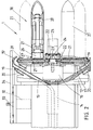
- the delivery device 1 has a drive housing 12 which is clad by a casing 13 shown in dash-dot lines in FIG.
- An electric motor (not shown) is accommodated in the drive housing 12, the rotor shaft 14 of which carries a guide tube 15 which is inclined to the radial. Its mouth end 15 'is bent in the direction of the rotor shaft axis.
- the rotor shaft 14 rotatably passes through the hub 16 of a bearing disk 17, which in turn is the carrier of a storage drum 18.
- the bearing disk 17 accommodates on its side facing away from the storage drum 18 magnets 19, which are opposed by counter magnets 20 which are fixed on the drive housing 12. In this way, the bearing disk 17 is secured against rotation and thus also the storage drum 18.
- the bearing disc 17 is equipped with six radially aligned threaded spindles 21 arranged in a uniform angular distribution.
- the inner end of each threaded spindle 21 carries a bevel gear 22.
- All bevel gears 22 mesh with a common ring gear 23 which is fixed on the axis 24 of a control motor 25 which can be switched in the direction of rotation.
- the axis 24 runs coaxially with the motor shaft 14.
- Each threaded spindle 21 engages through an internal thread of an individual motor 26, which drives a rod 27 tapering at its free end. Because of six threaded spindles 21, six rods 27 are accordingly also present, which form the storage drum 18. The rods serve to support the thread turns. These are generated by the rotation of the rotor shaft 14 together with the thread guide tube 15. The thread F passes through the mouth end 15 'onto the frustoconically widening, facing end 27' of the rod 27. The motor axis 28 of each individual motor 26 is extended and supports it of the radially freely projecting rod 27, see FIG. 2.
- Each rod 27 is flanked by two support strips 29 which run parallel to the longitudinal axis of the rod 27. Both support strips 29 assigned to a rod 27 are firmly connected to the single motor 26. This means that in the event of a radial displacement of the same, the support strips 29 are also moved. These therefore always maintain their position on rod 27. Slits 30 in a cover 31 overlapping the spindle drive serve to guide the support strips 29 parallel to the threaded spindle 21.
- the delivery device 1 is assigned a servomotor 32, by means of which a support unit 34 arranged parallel to the storage drum 18 can be displaced via an adjusting spindle 33.
- the carrying unit 34 receives a pin-like stopper 35, which can be activated and deactivated in the withdrawal path of the thread F.
- the stopper 35 is assigned to the upper rod 27 and aligned radially to the latter.
- the stopper 35 can be moved, for example, by electromagnetic means.
- each rod 27 is equipped with a fine thread 36 for transporting the thread turns to the free end of the storage drum.
- the fine thread 36 is such that, on the one hand, the thread turns are transported in the direction of the arrow without hitting or touching each other. On the other hand, the fine thread 36 permits trouble-free withdrawal of the thread from the storage drum 18.
- the stopper 35 When the weft thread 4 is inserted, the stopper 35 is in the release position. The weft thread 4 passes through the two interrogation points 10, 11 coupled to the control device, whereby the length of the weft thread 4 protruding from the fabric web 3 is registered. After the thread has been drawn off, the stopper 35 again enters its blocking position. If the weft thread 4 has the predetermined length, the control device 7 does not give any impulse to change the circumferential length of the storage drum 18. If, for example, the length of the weft thread 4 protruding from the fabric web 3 exceeds a predetermined value, the control device 7, which is in line connection with the two interrogation points 10, 11, gives the impulse, the circumferential length of the drum 18 to zoom out.
- control motor 25 drives the spindles 21 in the corresponding direction of rotation, the rods moving towards each other by a certain amount.
- the motor 32 is also controlled, which shifts the support unit 34 in the direction of the drum axis, so that the stopper 35 never leaves its starting position in relation to the facing rod 27.
- the variation of the circumferential length can take place during the operation of the delivery device 1, so that the weaving machine 2 does not need to be stopped.
- the control device 7 If, on the other hand, the length of the weft thread 4 protruding from the fabric web 3 is too short, this is communicated to the control device 7 via the inquiry points 10, 11. This then leads to an increase in the circumferential length of the storage drum 18 connected to the drive of the control motor 25 in the opposite direction, the rods 27 being displaced in the radially outward direction. This also applies to the carrying unit 34 with the stopper 35. In this way, the predetermined length of the weft thread 4 can be maintained very precisely while minimizing the loss of weft thread material.
Landscapes
- Engineering & Computer Science (AREA)
- Textile Engineering (AREA)
- Looms (AREA)
Applications Claiming Priority (2)
| Application Number | Priority Date | Filing Date | Title |
|---|---|---|---|
| DE4136481 | 1991-11-06 | ||
| DE19914136481 DE4136481A1 (de) | 1991-11-06 | 1991-11-06 | Liefervorrichtung zum eintragen vorbestimmter laengen von schussfaeden in webmaschinen oder dergleichen |
Publications (1)
| Publication Number | Publication Date |
|---|---|
| EP0540864A1 true EP0540864A1 (fr) | 1993-05-12 |
Family
ID=6444167
Family Applications (1)
| Application Number | Title | Priority Date | Filing Date |
|---|---|---|---|
| EP92115898A Withdrawn EP0540864A1 (fr) | 1991-11-06 | 1992-09-17 | Disposition d'alimentation pour l'insertion de fils de trame avec des longueurs prédéterminées dans les métiers à tisser ou analogues |
Country Status (2)
| Country | Link |
|---|---|
| EP (1) | EP0540864A1 (fr) |
| DE (1) | DE4136481A1 (fr) |
Cited By (3)
| Publication number | Priority date | Publication date | Assignee | Title |
|---|---|---|---|---|
| EP0832999A1 (fr) * | 1996-09-26 | 1998-04-01 | Micron Instrument Inc. | Système de contrÔle de fil de trame pour métiers à tisser |
| CN106460262A (zh) * | 2014-05-09 | 2017-02-22 | 必佳乐公司 | 输纬器装置 |
| IT202300028116A1 (it) * | 2023-12-27 | 2025-06-27 | Roj S R L | Porgitrama con tamburo a diametro regolabile per telai di tessitura comprendente un gruppo elettromagnete di rilascio del filo di trama munito di un dispositivo rapido di regolazione precisa della sua posizione di lavoro |
Citations (3)
| Publication number | Priority date | Publication date | Assignee | Title |
|---|---|---|---|---|
| EP0253359A2 (fr) * | 1986-07-14 | 1988-01-20 | Tsudakoma Corporation | Procédé pour régler la longueur de trame |
| EP0447680A1 (fr) * | 1990-03-22 | 1991-09-25 | SOBREVIN Société de brevets industriels-Etablissement | Dispositif de livraison d'un fil en mouvement |
| EP0469527A1 (fr) * | 1990-08-03 | 1992-02-05 | ROJ ELECTROTEX S.p.A. | Dispositif de réserve de trame pour les machines à tisser pneumatiques, comprenant un tambour de réserve de fil de diamètre réglable |
-
1991
- 1991-11-06 DE DE19914136481 patent/DE4136481A1/de not_active Withdrawn
-
1992
- 1992-09-17 EP EP92115898A patent/EP0540864A1/fr not_active Withdrawn
Patent Citations (3)
| Publication number | Priority date | Publication date | Assignee | Title |
|---|---|---|---|---|
| EP0253359A2 (fr) * | 1986-07-14 | 1988-01-20 | Tsudakoma Corporation | Procédé pour régler la longueur de trame |
| EP0447680A1 (fr) * | 1990-03-22 | 1991-09-25 | SOBREVIN Société de brevets industriels-Etablissement | Dispositif de livraison d'un fil en mouvement |
| EP0469527A1 (fr) * | 1990-08-03 | 1992-02-05 | ROJ ELECTROTEX S.p.A. | Dispositif de réserve de trame pour les machines à tisser pneumatiques, comprenant un tambour de réserve de fil de diamètre réglable |
Cited By (5)
| Publication number | Priority date | Publication date | Assignee | Title |
|---|---|---|---|---|
| EP0832999A1 (fr) * | 1996-09-26 | 1998-04-01 | Micron Instrument Inc. | Système de contrÔle de fil de trame pour métiers à tisser |
| CN106460262A (zh) * | 2014-05-09 | 2017-02-22 | 必佳乐公司 | 输纬器装置 |
| CN106460262B (zh) * | 2014-05-09 | 2018-11-13 | 必佳乐公司 | 输纬器装置 |
| IT202300028116A1 (it) * | 2023-12-27 | 2025-06-27 | Roj S R L | Porgitrama con tamburo a diametro regolabile per telai di tessitura comprendente un gruppo elettromagnete di rilascio del filo di trama munito di un dispositivo rapido di regolazione precisa della sua posizione di lavoro |
| EP4579017A1 (fr) * | 2023-12-27 | 2025-07-02 | Roj S.r.L. | Fournisseur de trame à tambour à diamètre réglable pour métiers à tisser, avec un électroaimant pour contrôler le relâchement du fil |
Also Published As
| Publication number | Publication date |
|---|---|
| DE4136481A1 (de) | 1993-05-13 |
Similar Documents
| Publication | Publication Date | Title |
|---|---|---|
| DE2225918C3 (de) | Verfahren für den Abzug fadenförmigen Materials von einem Wickelkörper einer Speichereinrichtung für Textilmaschinen und Einrichtung zur Durchführung des Verfahrens | |
| CH651862A5 (de) | Fangfadenaufwickelvorrichtung bei einem schuetzenlosen webstuhl. | |
| DE69504789T2 (de) | Schussfadenliefervorrichtung mit vorrichtung zum trennen von wendungen für schnelllaufende luftdüsenwebmaschinen | |
| DE4005418C1 (fr) | ||
| EP0524429A1 (fr) | Dispositif pour freiner distingtivement des fils ou des fils de fers et similaire | |
| CH693380A5 (de) | Verfahren und Vorrichtung zum Aufspulen eines kontinuierlich zulaufenden Fadens. | |
| EP0247967A1 (fr) | Dispositif de stockage de fil de trame pour un métier à tisser | |
| EP2251292B1 (fr) | Dispositif de paraffinage pour une machine textile fabriquant des bobines croisées | |
| DE2150301A1 (de) | Spul- und changiereinrichtung zum herstellen von wickeln aus garnen u.dgl | |
| DE3038969A1 (de) | Vorrichtung zum zufuehren des schussfadens in einer bandwebmaschine | |
| EP0725850A1 (fr) | Dispositif d'amenee du fil pour machines textiles | |
| DE3310438C2 (de) | Vorrichtung zur Veränderung des Durchmessers einer Ablaufhilfe für den Überkopfabzug eines auf eine Aufwickelspule aufzuwickelnden Fadens von einer Vorlagespule | |
| CH681802A5 (fr) | ||
| DE2221316B1 (de) | Vorrichtung zum Zwischenspeichern einer ueberschuessigen Fadenlaenge an einer Offen-End-Spinnmaschine | |
| DE4136481A1 (de) | Liefervorrichtung zum eintragen vorbestimmter laengen von schussfaeden in webmaschinen oder dergleichen | |
| DE4018124A1 (de) | Doppeldrahtzwirnspindelvorrichtung | |
| EP1083252A2 (fr) | Dispositif de préparation du fil de trame pour métiers à jet d'air | |
| DE2716017C2 (de) | Fadenbremse an einem Fadenspeicher | |
| EP0257464B1 (fr) | Procédé et dispositif de bobinage et le produit | |
| DE68904107T2 (de) | Vorrichtung zum bilden einer fadenreservewicklung auf eine leere huelse. | |
| DE2409466A1 (de) | Verfahren und anlage zum bearbeiten und handhaben von draht oder aehnlichem flexiblem strangmaterial | |
| DE1785436A1 (de) | Vorspinnmaschine | |
| DE2737048A1 (de) | Fadenspulmaschine zum automatischen verankern, verdrillen und aufwickeln eines fadens oder eines aehnlichen gegenstandes auf eine spule | |
| AT266658B (de) | Einrichtung an Spulmaschinen zum abfallosen Aufwickeln von Fadenmaterial | |
| DE1535643C2 (de) | Schußfaden Zwischenspeicher fur Webmaschinen mit feststehender Schuß faden Vorratsspule |
Legal Events
| Date | Code | Title | Description |
|---|---|---|---|
| PUAI | Public reference made under article 153(3) epc to a published international application that has entered the european phase |
Free format text: ORIGINAL CODE: 0009012 |
|
| AK | Designated contracting states |
Kind code of ref document: A1 Designated state(s): CH DE IT LI SE |
|
| 18W | Application withdrawn |
Withdrawal date: 19930420 |