EP0540896A1 - Machine à enrouler pour enrouler une bande, notamment une bande de papier - Google Patents
Machine à enrouler pour enrouler une bande, notamment une bande de papier Download PDFInfo
- Publication number
- EP0540896A1 EP0540896A1 EP92117246A EP92117246A EP0540896A1 EP 0540896 A1 EP0540896 A1 EP 0540896A1 EP 92117246 A EP92117246 A EP 92117246A EP 92117246 A EP92117246 A EP 92117246A EP 0540896 A1 EP0540896 A1 EP 0540896A1
- Authority
- EP
- European Patent Office
- Prior art keywords
- blade
- web
- support
- blade carrier
- carrier
- Prior art date
- Legal status (The legal status is an assumption and is not a legal conclusion. Google has not performed a legal analysis and makes no representation as to the accuracy of the status listed.)
- Granted
Links
Images



Classifications
-
- B—PERFORMING OPERATIONS; TRANSPORTING
- B65—CONVEYING; PACKING; STORING; HANDLING THIN OR FILAMENTARY MATERIAL
- B65H—HANDLING THIN OR FILAMENTARY MATERIAL, e.g. SHEETS, WEBS, CABLES
- B65H19/00—Changing the web roll
- B65H19/22—Changing the web roll in winding mechanisms or in connection with winding operations
- B65H19/26—Cutting-off the web running to the wound web roll
-
- B—PERFORMING OPERATIONS; TRANSPORTING
- B65—CONVEYING; PACKING; STORING; HANDLING THIN OR FILAMENTARY MATERIAL
- B65H—HANDLING THIN OR FILAMENTARY MATERIAL, e.g. SHEETS, WEBS, CABLES
- B65H2301/00—Handling processes for sheets or webs
- B65H2301/40—Type of handling process
- B65H2301/41—Winding, unwinding
- B65H2301/417—Handling or changing web rolls
- B65H2301/4187—Relative movement of core or web roll in respect of mandrel
- B65H2301/4189—Cutting
- B65H2301/41891—Cutting knife located between two winding rollers
Definitions
- the invention relates to a winding machine according to the preamble of claim 1. Reference is made to DE 41 28 095 A1.
- a similar winding machine has become known from DE 31 09 587 C2.
- the aim is to take measures to prevent the blade from damaging the drive surface of the roll wrapped in the web when the web is cut.
- the blade carrier is assigned a holding member which can be supported on the paper web and thus on the outer surface of the roll wrapped in the web at the moment of cutting, so that a certain minimum distance between the cutting edge of the blade and the outer surface of the roller remains.
- the holding member cooperates with a narrow edge provided with recesses with a perforating blade provided with corresponding recesses, which is moved towards the holding member essentially in the circumferential direction of the support roller at a distance from its surface.
- a separate bracket and a separate swivel drive are required for both the holding member and the perforating blade.
- DE-OS 26 38 368 relates to a winding machine in which a separating device is brought up from above via one of the two support rollers to the paper web to be cut, and which therefore belongs to a different genus.
- a pneumatic unit is used for the introduction.
- the winding machine according to the mentioned DE 41 28 095 A1 solves a particular problem that appears particularly unpleasantly with heavy, stiff types of paper. If the finished winding roll is ejected from the winding bed, so that the web to be cut rests under tension on the cutting edge of the blade, this exerts a force on the blade, and thus on the blade carrier and on the entire web cutting device.
- the web separator generally consists of a machine-wide plate that is supported at both ends. This plate and possibly the blade carrier are bent due to the aforementioned force. If the blade is no longer particularly sharp, this can result in the bend not cutting through the web at all.
- the problem is solved in that the blade carrier is designed as a double lever, one end of which supports the blade and the other end (support end) of which supports the blade carrier on the lateral surface of the carrier roller free of the web during the cutting process of the blade, so that a self-locking storage of the blade carrier takes place.
- the winding bed which is formed between the two support rollers is limited in its upper region by the outer surface of the roll. If the roll has a large diameter, it does not extend so far into the Space between the two support rollers; however, if it has a small diameter, it extends further down into the space between the two support rollers. The height of the space between the two support rollers in the area of the winding bed is therefore different, depending on whether it is a roll with a large or a small diameter.
- the separating device When the separating device is brought into position, it has to be moved a certain distance upwards, namely so far that the blade carrier can be tilted into the inclined position, one end of the blade-carrying end facing the web of material, while the other, so-called support end, is supported against the outer surface of the non-web-wrapped roller.
- the entire separating device - together with the blade carrier - can be lowered somewhat again. This means that the cutting device must be moved to a slightly higher position than is necessary for the cutting work before cutting the web. With regard to the limitation of the space between the two support rollers, this can become critical for rollers with a small diameter; the height of the room is then no longer sufficient.
- the invention has for its object to design a winding machine according to the preamble of claim 1 such that the winding bed height can be better used by the separating device does not have to be raised so far, so that even with smaller rolls, proper operation is guaranteed.
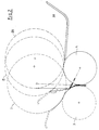
- FIG. 1 two carrier rollers 3 and 4 of a carrier roller winding machine can be seen.
- a finished paper roll 5 rests on the support rollers.
- the incoming web 6, which partially wraps around the support roller 3, has not yet been separated from the finished roll 5.
- a separating device has already been brought up between the two supporting rollers 3 and 4 in the gusset formed between the supporting rollers 3 and 4 and the winding 5.
- the separating device consists of a bar 7 guided on both sides, which has at its upper end a pivotably arranged blade carrier 8, to which a tear-off blade 9 is screwed.
- the rotatably mounted jacket is provided with a large number of bores 15. A vacuum can be applied inside. Carrier roller 4, however, asked for a closed outer surface.
- FIG. 2 shows further details of the entire machine, in particular the contour of the paper web 6 when the paper roll 5 is ejected. Individual positions of the paper roll are shown in dashed lines and identified by I, II and III.
- Fig. 3 again shows the rollers 3 and 4, and in the cutout.
- the blade carrier 8 has the blade 9 at one end, while its other end has a support surface 21.
- the blade carrier 8 is connected to the supporting structure 7 by means of a connecting member 40.
- joints 41 and 42 are provided. It can now be clearly seen that the blade carrier 8 can be moved into a tilted position, even without the entire separating device - including the supporting structure 7, the connecting member 40 and the blade carrier 8 - being able to be raised to a higher level.
- the blade support 8 can namely pivot due to the action of the link 40 already when starting up in the tilted position.
- the joint 42 does not necessarily have to rest on the blade-side end of the blade carrier 8. Rather, this joint could also be moved a little further towards the center of the connecting link.
- the support structure 7 does not have to consist of a single beam, but z. B. can be a latticework.
- the connecting member 40 - shown in the form of a rod in this side view - is in fact conceivable as a plate or as a plurality of parallel rods. The same applies to the blade carrier 8.
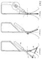
- FIG. 4 illustrates three positions that the blade carrier 8 and the connecting member 40 can assume.
- position 1 the entire unit, consisting of support structure 7, blade carrier 8 and connecting member 40, is moved into the basic position.
- Position 2 is an intermediate position.
- Position 3 is then the working position in which the paper web is finally cut.
- the adjustment mechanism comprises a pneumatic unit, with cylinder 50, piston rod 51 and pivot lever 52.
- the pivot lever 52 engages blade carrier 8 or is located in its extension.
- Fig. 5 illustrates the various forces that occur during the cutting process.
- the invention can also be used advantageously if the distance between the cutting edge of the blade 9 and the outer surface of the roller 3 is greater. Distances of several centimeters are conceivable.
- the angle between the connecting member 40 and the longitudinal center plane through the roller 5 need only be minimal. It is even conceivable that the connecting member 40 is absolutely vertical at the moment of cutting.
Landscapes
- Replacement Of Web Rolls (AREA)
- Paper (AREA)
- Winding Of Webs (AREA)
Applications Claiming Priority (2)
| Application Number | Priority Date | Filing Date | Title |
|---|---|---|---|
| DE4134361A DE4134361A1 (de) | 1991-10-17 | 1991-10-17 | Wickelmaschine zum aufwickeln einer warenbahn, insbesondere einer papierbahn |
| DE4134361 | 1991-10-17 |
Publications (2)
| Publication Number | Publication Date |
|---|---|
| EP0540896A1 true EP0540896A1 (fr) | 1993-05-12 |
| EP0540896B1 EP0540896B1 (fr) | 1995-02-22 |
Family
ID=6442883
Family Applications (1)
| Application Number | Title | Priority Date | Filing Date |
|---|---|---|---|
| EP92117246A Expired - Lifetime EP0540896B1 (fr) | 1991-10-17 | 1992-10-09 | Machine à enrouler pour enrouler une bande, notamment une bande de papier |
Country Status (7)
| Country | Link |
|---|---|
| US (1) | US5310130A (fr) |
| EP (1) | EP0540896B1 (fr) |
| JP (1) | JP3302413B2 (fr) |
| AT (1) | ATE118750T1 (fr) |
| CA (1) | CA2080625C (fr) |
| DE (2) | DE4134361A1 (fr) |
| FI (1) | FI108859B (fr) |
Cited By (1)
| Publication number | Priority date | Publication date | Assignee | Title |
|---|---|---|---|---|
| DE19901112A1 (de) * | 1999-01-14 | 2000-07-27 | Voith Sulzer Papiertech Patent | Rollenwickelvorrichtung |
Families Citing this family (8)
| Publication number | Priority date | Publication date | Assignee | Title |
|---|---|---|---|---|
| US4525142A (en) * | 1984-06-11 | 1985-06-25 | Research-Cottrell, Inc. | Process for treating flue gas with alkali injection and electron beam |
| DE4219541A1 (de) * | 1992-06-15 | 1993-12-16 | Jagenberg Ag | Tragwalzen-Wickelmaschine |
| DE59309354D1 (de) * | 1993-08-24 | 1999-03-11 | Beloit Technologies Inc | Wickelmaschine zum Wickeln von Bahnen |
| FI100324B (fi) * | 1994-12-13 | 1997-11-14 | Valmet Paper Machinery Inc | Menetelmä ja sovitelma radan katkaisemiseksi |
| CN1321868C (zh) * | 2002-02-06 | 2007-06-20 | 株式会社片冈机械制作所 | 片材分割卷取装置 |
| US6877689B2 (en) | 2002-09-27 | 2005-04-12 | C.G. Bretting Mfg. Co., Inc. | Rewinder apparatus and method |
| US7175127B2 (en) * | 2002-09-27 | 2007-02-13 | C.G. Bretting Manufacturing Company, Inc. | Rewinder apparatus and method |
| CN114277564A (zh) * | 2021-12-25 | 2022-04-05 | 诸暨凯发实业有限公司 | 一种赛络纺机织人棉布染色工艺 |
Citations (4)
| Publication number | Priority date | Publication date | Assignee | Title |
|---|---|---|---|---|
| US4368855A (en) * | 1980-02-14 | 1983-01-18 | Jagenberg Werke Ag | Web-cutting apparatus |
| US4444360A (en) * | 1981-03-13 | 1984-04-24 | J. M. Voith Gmbh | Web severing apparatus in a web winding machine |
| GB2183610A (en) * | 1985-11-28 | 1987-06-10 | Waertsilae Oy Ab | Web winding method and winder |
| DE4029914A1 (de) * | 1990-09-21 | 1992-03-26 | Jagenberg Ag | Tragwalzen-wickelmaschine |
Family Cites Families (9)
| Publication number | Priority date | Publication date | Assignee | Title |
|---|---|---|---|---|
| FI53560C (fi) * | 1976-03-12 | 1978-06-12 | Ahlstroem Oy | Foerfarande och anordning foer upprullning av materialbanor |
| DE2638368C2 (de) * | 1976-08-26 | 1983-08-25 | J.M. Voith Gmbh, 7920 Heidenheim | Verfahren und Doppeltragwalzen-Wickelmaschine zum Wickelwechsel nach dem Aufwickeln von Bahnen |
| DE2920707C2 (de) * | 1979-05-22 | 1990-05-31 | Jagenberg-Werke AG, 4000 Düsseldorf | Verfahren und Doppeltragwalzen-Wickelmaschine zum automatischen Trennen und Anwickeln einer Warenbahn |
| DE2930474C2 (de) * | 1979-07-27 | 1981-08-13 | J.M. Voith Gmbh, 7920 Heidenheim | Doppeltragwalzentwickelmaschine |
| AT373220B (de) * | 1979-07-27 | 1983-12-27 | Voith Gmbh J M | Doppeltragwalzenroller zum aufwickeln von materialbahnen |
| JPS5957849A (ja) * | 1982-09-22 | 1984-04-03 | Mitsubishi Heavy Ind Ltd | ウエブ巻取方法および装置 |
| DE3244966C1 (de) * | 1982-12-04 | 1984-06-07 | Jagenberg AG, 4000 Düsseldorf | Verfahren und Trenneinrichtung zum Durchtrennen von bahnfoermigem Zellstoff beim Anwickeln auf Wickelhuelsen |
| FI841655A7 (fi) * | 1983-06-13 | 1984-12-14 | Jagenberg Ag | Menetelmä rainojen katkaisemiseksi kelauskoneissa. |
| JPS60232358A (ja) * | 1984-05-01 | 1985-11-19 | Kawanoe Zoki Kk | ウエブ巻取装置におけるウエブの切断装置 |
-
1991
- 1991-10-17 DE DE4134361A patent/DE4134361A1/de not_active Withdrawn
-
1992
- 1992-10-09 DE DE59201460T patent/DE59201460D1/de not_active Expired - Fee Related
- 1992-10-09 EP EP92117246A patent/EP0540896B1/fr not_active Expired - Lifetime
- 1992-10-09 AT AT92117246T patent/ATE118750T1/de not_active IP Right Cessation
- 1992-10-15 CA CA002080625A patent/CA2080625C/fr not_active Expired - Fee Related
- 1992-10-15 FI FI924675A patent/FI108859B/fi not_active IP Right Cessation
- 1992-10-16 US US07/962,471 patent/US5310130A/en not_active Expired - Fee Related
- 1992-10-19 JP JP27999092A patent/JP3302413B2/ja not_active Expired - Fee Related
Patent Citations (4)
| Publication number | Priority date | Publication date | Assignee | Title |
|---|---|---|---|---|
| US4368855A (en) * | 1980-02-14 | 1983-01-18 | Jagenberg Werke Ag | Web-cutting apparatus |
| US4444360A (en) * | 1981-03-13 | 1984-04-24 | J. M. Voith Gmbh | Web severing apparatus in a web winding machine |
| GB2183610A (en) * | 1985-11-28 | 1987-06-10 | Waertsilae Oy Ab | Web winding method and winder |
| DE4029914A1 (de) * | 1990-09-21 | 1992-03-26 | Jagenberg Ag | Tragwalzen-wickelmaschine |
Cited By (3)
| Publication number | Priority date | Publication date | Assignee | Title |
|---|---|---|---|---|
| DE19901112A1 (de) * | 1999-01-14 | 2000-07-27 | Voith Sulzer Papiertech Patent | Rollenwickelvorrichtung |
| US6322020B1 (en) * | 1999-01-14 | 2001-11-27 | Voith Sulzer Papiertechnik Patent Gmbh | Reel winding device and process having cutter holder movable in accordance with a wound roll diameter |
| DE19901112B4 (de) * | 1999-01-14 | 2004-04-01 | Voith Paper Patent Gmbh | Rollenwickelvorrichtung |
Also Published As
| Publication number | Publication date |
|---|---|
| JPH05193796A (ja) | 1993-08-03 |
| JP3302413B2 (ja) | 2002-07-15 |
| FI108859B (fi) | 2002-04-15 |
| DE4134361A1 (de) | 1993-04-22 |
| FI924675L (fi) | 1993-04-18 |
| EP0540896B1 (fr) | 1995-02-22 |
| US5310130A (en) | 1994-05-10 |
| CA2080625A1 (fr) | 1993-04-18 |
| FI924675A0 (fi) | 1992-10-15 |
| ATE118750T1 (de) | 1995-03-15 |
| CA2080625C (fr) | 1998-04-21 |
| DE59201460D1 (de) | 1995-03-30 |
Similar Documents
| Publication | Publication Date | Title |
|---|---|---|
| DE19513143C2 (de) | Wickelmaschine zum Aufwickeln einer laufenden Bahn, insbesondere einer Papierbahn, zu einer Rolle | |
| DE3727339A1 (de) | Vorrichtung zum wechseln von auf eine vorratsrolle aufgewickelten folienbahnen | |
| EP0540896B1 (fr) | Machine à enrouler pour enrouler une bande, notamment une bande de papier | |
| DE2942883C2 (de) | Vorrichtung zum Verschließen des Bodens einer rechteckigen aufgerichteten Faltschachtel | |
| EP0791549B1 (fr) | Méthode et dispositif pour enrouler une bande de matériau coupée en long | |
| DE19904180C1 (de) | Kalander | |
| EP1334527A1 (fr) | Separateur en forme de manche et son dispositif de production | |
| DE2451469C3 (de) | Verfahren und Vorrichtung zum Herstellen eines gefalteten Bogens aus Papier, Folie od. dgl | |
| DE3629217A1 (de) | Vorrichtung zum aufwickeln einer warenbahn | |
| EP0327725B1 (fr) | Bobineuse avec cylindres porteurs pour enrouler une feuille continue, notamment une feuille continue en papier ou carton, aux mandrins | |
| EP0406581B1 (fr) | Dispositif pour couper une bande sur un rouleau d'inversement | |
| DE9112927U1 (de) | Wickelmaschine zum Aufwickeln einer Warenbahn, insbesondere einer Papierbahn | |
| DE1965299A1 (de) | Vorrichtung zum Aufwickeln von band- oder bahnfoermigem Material im Kontaktwalzen-Verfahren | |
| DE1223682B (de) | Vorrichtung zum Aussortieren von Bogen aus Papier, Pappe od. dgl. | |
| DE2728202C3 (de) | Querteilschere für Walzbleche, insbesondere für Grobbleche | |
| CH673483A5 (fr) | ||
| DE4128095C1 (fr) | ||
| DE68909791T2 (de) | Vorrichtung zum verbinden von zwei materialbahnen. | |
| DE3143011A1 (de) | Steuerkurvenbetaetigte greifvorrichtung fuer bedruckte papierbahnen | |
| DE3916156A1 (de) | Maschine zum herstellen von akkordeonfalten bei materialbahnen | |
| DE8708849U1 (de) | Doppeltragwalzen-Wickelmaschine | |
| EP1444156A1 (fr) | Dispositif d'enroulement de bandes en continu | |
| DE2913351A1 (de) | Vorrichtung zum vorbrechen, vollen aufrichten und ueberbrechen platt zusammengeklappter faltschachteln aus karton, kunststoff-folie o.dgl. | |
| DE2913308A1 (de) | Vorrichtung zum vorbrechen, vollen aufrichten und ueberbrechen platt zusammengeklappter faltschachteln aus karton, kunststoff-folie o.dgl. | |
| DD148014A1 (de) | Richtmaschine |
Legal Events
| Date | Code | Title | Description |
|---|---|---|---|
| PUAI | Public reference made under article 153(3) epc to a published international application that has entered the european phase |
Free format text: ORIGINAL CODE: 0009012 |
|
| 17P | Request for examination filed |
Effective date: 19921009 |
|
| AK | Designated contracting states |
Kind code of ref document: A1 Designated state(s): AT CH DE FR GB IT LI SE |
|
| 17Q | First examination report despatched |
Effective date: 19940707 |
|
| GRAA | (expected) grant |
Free format text: ORIGINAL CODE: 0009210 |
|
| AK | Designated contracting states |
Kind code of ref document: B1 Designated state(s): AT CH DE FR GB IT LI SE |
|
| REF | Corresponds to: |
Ref document number: 118750 Country of ref document: AT Date of ref document: 19950315 Kind code of ref document: T |
|
| GBT | Gb: translation of ep patent filed (gb section 77(6)(a)/1977) |
Effective date: 19950224 |
|
| REF | Corresponds to: |
Ref document number: 59201460 Country of ref document: DE Date of ref document: 19950330 |
|
| ET | Fr: translation filed | ||
| ITF | It: translation for a ep patent filed | ||
| PLBE | No opposition filed within time limit |
Free format text: ORIGINAL CODE: 0009261 |
|
| 26N | No opposition filed | ||
| PGFP | Annual fee paid to national office [announced via postgrant information from national office to epo] |
Ref country code: GB Payment date: 20000925 Year of fee payment: 9 |
|
| PGFP | Annual fee paid to national office [announced via postgrant information from national office to epo] |
Ref country code: FR Payment date: 20001017 Year of fee payment: 9 |
|
| PGFP | Annual fee paid to national office [announced via postgrant information from national office to epo] |
Ref country code: AT Payment date: 20001019 Year of fee payment: 9 |
|
| PGFP | Annual fee paid to national office [announced via postgrant information from national office to epo] |
Ref country code: CH Payment date: 20001030 Year of fee payment: 9 |
|
| PG25 | Lapsed in a contracting state [announced via postgrant information from national office to epo] |
Ref country code: GB Free format text: LAPSE BECAUSE OF NON-PAYMENT OF DUE FEES Effective date: 20011009 Ref country code: AT Free format text: LAPSE BECAUSE OF NON-PAYMENT OF DUE FEES Effective date: 20011009 |
|
| PG25 | Lapsed in a contracting state [announced via postgrant information from national office to epo] |
Ref country code: LI Free format text: LAPSE BECAUSE OF NON-PAYMENT OF DUE FEES Effective date: 20011031 Ref country code: CH Free format text: LAPSE BECAUSE OF NON-PAYMENT OF DUE FEES Effective date: 20011031 |
|
| REG | Reference to a national code |
Ref country code: GB Ref legal event code: IF02 |
|
| GBPC | Gb: european patent ceased through non-payment of renewal fee |
Effective date: 20011009 |
|
| REG | Reference to a national code |
Ref country code: CH Ref legal event code: PL |
|
| PG25 | Lapsed in a contracting state [announced via postgrant information from national office to epo] |
Ref country code: FR Free format text: LAPSE BECAUSE OF NON-PAYMENT OF DUE FEES Effective date: 20020628 |
|
| REG | Reference to a national code |
Ref country code: FR Ref legal event code: ST |
|
| PGFP | Annual fee paid to national office [announced via postgrant information from national office to epo] |
Ref country code: SE Payment date: 20021021 Year of fee payment: 11 |
|
| PG25 | Lapsed in a contracting state [announced via postgrant information from national office to epo] |
Ref country code: SE Free format text: LAPSE BECAUSE OF NON-PAYMENT OF DUE FEES Effective date: 20031010 |
|
| EUG | Se: european patent has lapsed | ||
| PG25 | Lapsed in a contracting state [announced via postgrant information from national office to epo] |
Ref country code: IT Free format text: LAPSE BECAUSE OF NON-PAYMENT OF DUE FEES;WARNING: LAPSES OF ITALIAN PATENTS WITH EFFECTIVE DATE BEFORE 2007 MAY HAVE OCCURRED AT ANY TIME BEFORE 2007. THE CORRECT EFFECTIVE DATE MAY BE DIFFERENT FROM THE ONE RECORDED. Effective date: 20051009 |
|
| PGFP | Annual fee paid to national office [announced via postgrant information from national office to epo] |
Ref country code: DE Payment date: 20051014 Year of fee payment: 14 |
|
| PG25 | Lapsed in a contracting state [announced via postgrant information from national office to epo] |
Ref country code: DE Free format text: LAPSE BECAUSE OF NON-PAYMENT OF DUE FEES Effective date: 20070501 |