EP0540920A2 - Broyeur à impact - Google Patents
Broyeur à impact Download PDFInfo
- Publication number
- EP0540920A2 EP0540920A2 EP92117691A EP92117691A EP0540920A2 EP 0540920 A2 EP0540920 A2 EP 0540920A2 EP 92117691 A EP92117691 A EP 92117691A EP 92117691 A EP92117691 A EP 92117691A EP 0540920 A2 EP0540920 A2 EP 0540920A2
- Authority
- EP
- European Patent Office
- Prior art keywords
- impact
- sensor
- impact body
- wear
- mill according
- Prior art date
- Legal status (The legal status is an assumption and is not a legal conclusion. Google has not performed a legal analysis and makes no representation as to the accuracy of the status listed.)
- Granted
Links
- 238000004458 analytical method Methods 0.000 claims description 9
- 230000004888 barrier function Effects 0.000 claims description 9
- 238000013461 design Methods 0.000 claims description 9
- 239000000463 material Substances 0.000 claims description 8
- 238000002604 ultrasonography Methods 0.000 claims description 6
- 230000001939 inductive effect Effects 0.000 claims description 5
- 230000003287 optical effect Effects 0.000 claims description 5
- 230000009471 action Effects 0.000 claims description 4
- 238000005259 measurement Methods 0.000 claims description 2
- 238000000034 method Methods 0.000 claims description 2
- 230000008569 process Effects 0.000 claims description 2
- 230000005855 radiation Effects 0.000 claims 2
- 230000011514 reflex Effects 0.000 claims 2
- 230000003213 activating effect Effects 0.000 claims 1
- 230000008859 change Effects 0.000 claims 1
- 230000009467 reduction Effects 0.000 claims 1
- 230000004580 weight loss Effects 0.000 claims 1
- 235000013339 cereals Nutrition 0.000 description 7
- 238000010276 construction Methods 0.000 description 4
- 230000001965 increasing effect Effects 0.000 description 3
- 230000015572 biosynthetic process Effects 0.000 description 2
- 238000011156 evaluation Methods 0.000 description 2
- 230000006978 adaptation Effects 0.000 description 1
- 230000005540 biological transmission Effects 0.000 description 1
- 239000000428 dust Substances 0.000 description 1
- 230000002349 favourable effect Effects 0.000 description 1
- 238000010191 image analysis Methods 0.000 description 1
- 238000004519 manufacturing process Methods 0.000 description 1
- 238000012544 monitoring process Methods 0.000 description 1
- 238000009420 retrofitting Methods 0.000 description 1
- 238000001228 spectrum Methods 0.000 description 1
- 239000004575 stone Substances 0.000 description 1
- 210000002105 tongue Anatomy 0.000 description 1
- 238000012549 training Methods 0.000 description 1
Images
Classifications
-
- B—PERFORMING OPERATIONS; TRANSPORTING
- B02—CRUSHING, PULVERISING, OR DISINTEGRATING; PREPARATORY TREATMENT OF GRAIN FOR MILLING
- B02C—CRUSHING, PULVERISING, OR DISINTEGRATING IN GENERAL; MILLING GRAIN
- B02C19/00—Other disintegrating devices or methods
- B02C19/0012—Devices for disintegrating materials by collision of these materials against a breaking surface or breaking body and/or by friction between the material particles (also for grain)
- B02C19/0018—Devices for disintegrating materials by collision of these materials against a breaking surface or breaking body and/or by friction between the material particles (also for grain) using a rotor accelerating the materials centrifugally against a circumferential breaking surface
- B02C19/0025—Devices for disintegrating materials by collision of these materials against a breaking surface or breaking body and/or by friction between the material particles (also for grain) using a rotor accelerating the materials centrifugally against a circumferential breaking surface by means of a rotor with radially extending channels
-
- B—PERFORMING OPERATIONS; TRANSPORTING
- B02—CRUSHING, PULVERISING, OR DISINTEGRATING; PREPARATORY TREATMENT OF GRAIN FOR MILLING
- B02B—PREPARING GRAIN FOR MILLING; REFINING GRANULAR FRUIT TO COMMERCIAL PRODUCTS BY WORKING THE SURFACE
- B02B3/00—Hulling; Husking; Decorticating; Polishing; Removing the awns; Degerming
Definitions
- the invention relates to an impact mill with a housing in which a centrifugal rotor which can be driven and rotated about an axis of rotation and an impact body which surrounds this centrifugal rotor are arranged.
- Impact mills of this type are known in numerous embodiments and for a wide variety of purposes.
- An example with a closed, annular impact body is shown in US Pat. No. 2,352,327, an impact body consisting of several segments is illustrated by DE-C-30 11 112. While the former impact mill for peeling nuts, in particular cereals with one of the grains surrounding shell, the latter is used to grind stone.
- US-A-2,352,327 shows an impact ring that can be moved up and down, so that the wear is evened out over its surface. Although this extends the service life of such a ring, it is only possible to determine when the final time for a replacement has come when the mill is at a standstill.
- DE-A-41 03 468 also deals with the problem of uniform wear, taking a different path than the US-A mentioned. But even here the problem remains unsolved to recognize the right time to replace the impact ring.
- the invention is therefore based on the object of designing an impact mill of the type mentioned at the outset in such a way that it is unnecessary to switch off the mill for the purpose of checking the impact ring and the impact ring can nevertheless continue to function for as long as possible in order to reduce the frequency of replacement .
- the impact body is assigned at least one sensor which functions during the operation of the mill and is provided for detecting at least the functionality, preferably also for determining the extent of wear of the impact body. This makes it possible to determine at any time whether the mill is properly equipped. Unexpected interruptions in the grinding operation can advantageously be avoided.
- At least one sensor is assigned to each segment part, preferably its impact surface areas, in a further embodiment of the invention. This is also advantageous in the case of a closed ring, because the wear can sometimes be unilateral or different.
- the senor is arranged to scan the impact body through an opening in its ring-shaped or cylindrical version of the impact body. This arrangement permits a particularly simple construction of the sensor and also enables retrofitting of impact mills already in use with one or - if appropriate - with several sensors.
- a finger is provided on the impact body under the action of a loading device and enters the interior of its annular arrangement and design when the impact body is worn through, a switching signal for a display device from this position of the finger and / or can be derived for a shutdown device of the impact mill drive.
- a switching signal for a display device from this position of the finger and / or can be derived for a shutdown device of the impact mill drive.
- the opening in the socket for the impact body is designed as a slot opening, and that the finger is integrally connected to a spring arm which is supported on a stop surface of a finger carrier, preferably under the force of a leg spring .
- This embodiment according to the invention advantageously represents a construction that can be used in the simplest way in all types of impact mills. It requires little space and only requires low manufacturing costs.
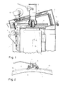
- An impact mill has a housing 1 with a cover 2.
- a centrifugal rotor 3 which can be driven to rotate by means of a motor 4.
- a feed pipe 6 via which the nuts or grains can be fed to the center of the rotor 3. The grains are then thrown through the channels 5 due to the rotation about an axis of rotation 8 and the centrifugal force generated thereby against a baffle ring 7.
- This impact ring 7 is therefore subject to increasing wear.
- This wear and tear can be made more uniform by an angle alpha of the axis 10 of this impact ring 7 with respect to the axis 8 if the impact ring 7 is driven to rotate by a motor 9.
- the details of this construction which is preferably used in the context of the invention, since the location of the attachment of a sensor is then relatively uncritical, can be found in the aforementioned DE-A-41 03 468.
- the above-mentioned sensor provided according to the invention consists of a scanning finger 11, which can be seen particularly in FIG. 2, which rests on the outside of the baffle ring 7 under the action of a loading device through a slot opening 12 of a socket 13 receiving the baffle ring 7.
- this loading device is formed by a spring arm 14 which is connected in one piece to the finger 11 and which is supported on a stop surface 15 of a finger carrier 16.
- the finger 11 is not shown under the action of the spring arm 14 or one connected to the arms 11 and 14 Leg spring pressed into the interior of the slot 12 and through it. You will then be able to recognize this state of the impact ring 7 from the position of the arm 14 or to be able to sense it with the aid of a sensor (optical, with contact tongues electrical, inductive or capacitive) which senses the position of the arm 14. If the arm 14 itself is designed as a loading device, its position when the impact ring 7 wears will be indefinite. If an additional loading device (magnet, spring, gas spring or the like) is provided, the arm 14 will turn counterclockwise turn around a bolt 17 holding it.
- the socket 13 will advantageously prevent the ring from falling apart and this socket is probably at least part of the outer surface of the baffle 7 should cover
- this can of course also be done with other sensors instead of the mechanical sensor 11 shown.
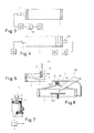
- FIG. 3 shows, for example, an ultrasound sensor 111 which is arranged opposite the outer wall of the impact ring 7.
- the ultrasound sensor 111 preferably operates alternately in the transmission mode and in the reception mode in order to be able to carry out a distance measurement. If the outer wall of the baffle ring 7 is intact - as shown in full lines - the sensor 111 will only detect a relatively short distance. However, should the ring 7 break through in its central area opposite the sensor 111 because it is already too worn out, the ultrasonic waves will only be reflected by the opposite inner wall of the ring 7, i.e. the distance has increased accordingly.
- a distance evaluation circuit 18 and a subsequent discrimination stage 19 in particular a simple threshold switch, to the sensor 111 in order to determine whether the received signals correspond to the short or long distance, which is indicated by a display device 20 (optical and / or acoustic) can be reported.
- such a distance measuring system can be designed in any manner known per se, for example also as a basic distance measuring system. It would also be conceivable to provide a receiver on the inside of the impact ring 7 in order to operate the sensor 111 to a certain extent as a “barrier”, for example as a light barrier (if the sensor 111 is designed as a light transmitter). Of course you can the arrangement of transmitter and receiver can then be reversed and the transmitter inside, the receiver outside, can be arranged. Last but not least, the advantages of such an arrangement are that a clear signal is obtained even if the impact ring 7 is rotatably arranged, as can be seen from FIG. 1. Intermittent signals are then produced when the slot or slot opening 12 that has been worn out passes. However, it is also understood that a plurality of sensors can be provided over the height of the impact ring, and that a number of such slot openings (and, if appropriate, sensors) can also be distributed.
- a vibration generator 111 ' can be dispensed with if one assumes that the grains bouncing against the inner wall of the baffle ring itself produce vibrations which - with a relatively constant supply of the grains - are also proportionate will be regular.
- a light source 22 carried by a holder 23 protruding into the impact ring 7 emits light against the inner surface of the impact ring 7. As long as this inner surface is still intact, the light is reflected against a photoelectric converter 311 (dashed beam).
- FIG. 6 A particularly simple variant can be seen in FIG. 6.
- a cylinder sleeve 24 is fastened to the housing cover 2, in which an inner sleeve 25 is guided telescopically.
- This inner sleeve 25 is fastened to the end of a tension spring 26 which is connected to a force transducer 411.
- a threshold switch cf. 19
- FIG. 6 shows a rotor disk 103 without internal channels (possibly with radial centrifugal walls), in the middle of which the material to be impacted is fed in via a chute 106.
- FIG. 7 illustrates an indirect determination of the degree of wear of the impact ring 7, in which the impacted material is then subjected to an analysis of the efficiency of the impact process in an analysis device 27.
- samples are taken within the analysis device 27, for example, which should help determine the degree of peeling or the degree of comminution of the material.
- the device 27 may include an image analysis device as is known per se and is described, for example, in DE-A-40 29 202.
- the grains, preferably in an ordered position and at a predetermined speed, are presented to a video camera which is connected to an image analyzer for determining the color and / or size.
- Another possibility is to design the analyzing device 27 with a separating device, in particular with an air classifier, through which the shells can be separated from the cores. The amount of shells is then compared to the amount of cores, which checks the peeling result can. Conclusions about the degree of wear of the impact ring 7 can then be drawn from this peeling result.
Landscapes
- Engineering & Computer Science (AREA)
- Food Science & Technology (AREA)
- Developing Agents For Electrophotography (AREA)
- Compositions Of Macromolecular Compounds (AREA)
- Graft Or Block Polymers (AREA)
- Crushing And Grinding (AREA)
- Measurement Of Mechanical Vibrations Or Ultrasonic Waves (AREA)
- Crushing And Pulverization Processes (AREA)
- Investigating Strength Of Materials By Application Of Mechanical Stress (AREA)
Applications Claiming Priority (2)
| Application Number | Priority Date | Filing Date | Title |
|---|---|---|---|
| DE4136575 | 1991-11-07 | ||
| DE4136575A DE4136575A1 (de) | 1991-11-07 | 1991-11-07 | Prallmuehle |
Publications (3)
| Publication Number | Publication Date |
|---|---|
| EP0540920A2 true EP0540920A2 (fr) | 1993-05-12 |
| EP0540920A3 EP0540920A3 (en) | 1993-12-29 |
| EP0540920B1 EP0540920B1 (fr) | 1997-03-26 |
Family
ID=6444226
Family Applications (1)
| Application Number | Title | Priority Date | Filing Date |
|---|---|---|---|
| EP92117691A Expired - Lifetime EP0540920B1 (fr) | 1991-11-07 | 1992-10-16 | Broyeur à impact |
Country Status (4)
| Country | Link |
|---|---|
| US (1) | US5407141A (fr) |
| EP (1) | EP0540920B1 (fr) |
| AT (1) | ATE150669T1 (fr) |
| DE (2) | DE4136575A1 (fr) |
Families Citing this family (3)
| Publication number | Priority date | Publication date | Assignee | Title |
|---|---|---|---|---|
| SE532108C2 (sv) * | 2004-12-08 | 2009-10-27 | Aake Faektenmark | Träningsanordning |
| US7172144B1 (en) * | 2006-03-09 | 2007-02-06 | Dennis Slater | System for measuring wear in a grinding mill |
| EP4620573A3 (fr) * | 2021-10-05 | 2025-12-03 | Bühler AG | Anneau d'impact et dispositif de décorticage amélioré |
Family Cites Families (12)
| Publication number | Priority date | Publication date | Assignee | Title |
|---|---|---|---|---|
| US2352327A (en) * | 1942-03-07 | 1944-06-27 | Quaker Oats Co | Grain huller |
| US2941732A (en) * | 1958-02-12 | 1960-06-21 | Reserve Mining Co | Dimensional indicator for inaccessible location |
| ZA747312B (en) * | 1973-11-17 | 1975-12-31 | Kloeckner Humboldt Deutz Ag | Method of determining and setting the width of the crushing gap and of measuring crushing tool wear in a a rotary crushing by aultrsonicmeans, and torary crusher for carrying out the method |
| DE2434837C2 (de) * | 1974-07-19 | 1976-08-19 | Hazemag Andreas Kg | Prallmuehle mit einer mahlbahn, die aus nebeneinander geschichteten schlag- oder pralleisten besteht |
| SU1146084A1 (ru) * | 1983-10-25 | 1985-03-23 | Криворожский Ордена Трудового Красного Знамени Горно-Рудный Институт | Система автоматического управлени измельчительным комплексом |
| AT389653B (de) * | 1985-09-10 | 1990-01-10 | Schroedl Hermann | Verfahren zur einstellung der spaltweite eines kegelbrechers od.dgl. |
| US4820980A (en) * | 1987-05-04 | 1989-04-11 | Dodson Edgars Darryl | Gap, wear and tram measurement system and method for grinding machines |
| SE456138B (sv) * | 1987-09-10 | 1988-09-12 | Boliden Ab | Forfarande for reglering av krosspaltbredden i en gyratorisk kross |
| DD301325A7 (de) * | 1990-01-02 | 1992-12-03 | Energiewerke Schwarze Pumpe Ag,De | Vorrichtung zur anzeige der grenznutzungsdauer von schlagraedern |
| DD301241A7 (de) * | 1990-01-02 | 1992-11-05 | Energiewerke Schwarze Pumpe Ag,De | Einrichtung zur grenzwertanzeige des schlagplattenverschleisses an schlagraedern |
| DE4029202A1 (de) * | 1990-09-14 | 1992-03-19 | Buehler Ag | Verfahren zum sortieren von partikeln eines schuettgutes und vorrichtungen hierfuer |
| DE4103468C2 (de) * | 1991-02-06 | 2001-07-12 | Buehler Gmbh | Prallmühle |
-
1991
- 1991-11-07 DE DE4136575A patent/DE4136575A1/de not_active Withdrawn
-
1992
- 1992-10-16 EP EP92117691A patent/EP0540920B1/fr not_active Expired - Lifetime
- 1992-10-16 AT AT92117691T patent/ATE150669T1/de not_active IP Right Cessation
- 1992-10-16 DE DE59208266T patent/DE59208266D1/de not_active Expired - Fee Related
-
1993
- 1993-09-30 US US08/129,792 patent/US5407141A/en not_active Expired - Fee Related
Also Published As
| Publication number | Publication date |
|---|---|
| DE4136575A1 (de) | 1993-05-13 |
| EP0540920B1 (fr) | 1997-03-26 |
| DE59208266D1 (de) | 1997-04-30 |
| EP0540920A3 (en) | 1993-12-29 |
| ATE150669T1 (de) | 1997-04-15 |
| US5407141A (en) | 1995-04-18 |
Similar Documents
| Publication | Publication Date | Title |
|---|---|---|
| EP3984644B1 (fr) | Concasseur à percussion | |
| CN104923370A (zh) | 金属硅粉制备工艺及装置 | |
| EP3669030B1 (fr) | Système de détermination de l'usure d'éléments abrasifs sur un appareil à roue à aubes | |
| EP1255612A1 (fr) | Procede et dispositif pour broyer des copeaux | |
| WO2018224118A1 (fr) | Dispositif pour la séparation de conglomérats composés de matériaux de densités différentes | |
| WO2017045918A1 (fr) | Procédé de fonctionnement d'un broyeur tubulaire, ensemble permettant de déterminer des données caractéristiques d'un broyeur tubulaire et broyeur tubulaire | |
| DE102016110086B4 (de) | Vorrichtung zum Auftrennen von Konglomeraten, die aus Materialien unterschiedlicher Dichte bestehen | |
| DE3906089C2 (de) | Vorrichtung zum Aussondern harter Gegenstände aus einem Holzstrom | |
| EP0540920A2 (fr) | Broyeur à impact | |
| CN114522757A (zh) | 一种猪饲料生物添加剂加工装置 | |
| DE19933995A1 (de) | Füllstandsmessung für Kugelmühlen | |
| DE2744053C2 (de) | Stofflöser zum Auflösen von Altpapier | |
| CA1191822A (fr) | Broyeur a disques tournants | |
| DE68917566T2 (de) | Vorrichtung und Verfahren zum Zerkleinern von Mineralfeststoffen in kleine Teilchen und Verfahren zum Sortieren von Mineralfeststoffteilchen nach Grösse. | |
| CN206868607U (zh) | 一种建筑机械用感应式物料分级装置 | |
| DE2620797A1 (de) | Schlaegermuehle | |
| CN211463336U (zh) | 一种洗煤厂使用的原煤破碎机 | |
| DE3116159C2 (de) | Verfahren zum Prallzerkleinern von harten Materialien wie Hartgestein oder dgl. und Prallbrecher zur Durchführung des Verfahrens | |
| DE2537880C3 (de) | Vorrichtung zum Zerkleinern von Mahlgut | |
| CN211865360U (zh) | 一种磨矿用筛分机 | |
| DE273577C (fr) | ||
| CN215541538U (zh) | 一种改进型气流磨固定机构 | |
| DE881181C (de) | Vorrichtung zum Entwaessern von feinkoernigem Gut | |
| DE972313C (de) | Stehende Zentrifuge zum Entwaessern von feinkoernigem Gut, insbesondere von Schlamm | |
| DE960042C (de) | Vorrichtung zum Schroten und Vermahlen landwirtschaftlicher Produkte |
Legal Events
| Date | Code | Title | Description |
|---|---|---|---|
| PUAI | Public reference made under article 153(3) epc to a published international application that has entered the european phase |
Free format text: ORIGINAL CODE: 0009012 |
|
| AK | Designated contracting states |
Kind code of ref document: A2 Designated state(s): AT BE CH DE DK ES FR GB GR IT LI LU NL PT SE |
|
| PUAL | Search report despatched |
Free format text: ORIGINAL CODE: 0009013 |
|
| AK | Designated contracting states |
Kind code of ref document: A3 Designated state(s): AT BE CH DE DK ES FR GB GR IT LI LU NL PT SE |
|
| 17P | Request for examination filed |
Effective date: 19931125 |
|
| 17Q | First examination report despatched |
Effective date: 19950606 |
|
| GRAG | Despatch of communication of intention to grant |
Free format text: ORIGINAL CODE: EPIDOS AGRA |
|
| GRAH | Despatch of communication of intention to grant a patent |
Free format text: ORIGINAL CODE: EPIDOS IGRA |
|
| GRAH | Despatch of communication of intention to grant a patent |
Free format text: ORIGINAL CODE: EPIDOS IGRA |
|
| GRAA | (expected) grant |
Free format text: ORIGINAL CODE: 0009210 |
|
| AK | Designated contracting states |
Kind code of ref document: B1 Designated state(s): AT BE CH DE DK ES FR GB GR IT LI LU NL PT SE |
|
| PG25 | Lapsed in a contracting state [announced via postgrant information from national office to epo] |
Ref country code: NL Free format text: LAPSE BECAUSE OF FAILURE TO SUBMIT A TRANSLATION OF THE DESCRIPTION OR TO PAY THE FEE WITHIN THE PRESCRIBED TIME-LIMIT Effective date: 19970326 Ref country code: ES Free format text: THE PATENT HAS BEEN ANNULLED BY A DECISION OF A NATIONAL AUTHORITY Effective date: 19970326 Ref country code: GB Effective date: 19970326 Ref country code: FR Effective date: 19970326 Ref country code: GR Free format text: LAPSE BECAUSE OF FAILURE TO SUBMIT A TRANSLATION OF THE DESCRIPTION OR TO PAY THE FEE WITHIN THE PRESCRIBED TIME-LIMIT Effective date: 19970326 Ref country code: DK Effective date: 19970326 Ref country code: IT Free format text: LAPSE BECAUSE OF FAILURE TO SUBMIT A TRANSLATION OF THE DESCRIPTION OR TO PAY THE FEE WITHIN THE PRE;WARNING: LAPSES OF ITALIAN PATENTS WITH EFFECTIVE DATE BEFORE 2007 MAY HAVE OCCURRED AT ANY TIME BEFORE 2007. THE CORRECT EFFECTIVE DATE MAY BE DIFFERENT FROM THE ONE RECORDED.SCRIBED TIME-LIMIT Effective date: 19970326 |
|
| REF | Corresponds to: |
Ref document number: 150669 Country of ref document: AT Date of ref document: 19970415 Kind code of ref document: T |
|
| REG | Reference to a national code |
Ref country code: CH Ref legal event code: EP Ref country code: CH Ref legal event code: NV Representative=s name: BUEHLER AG PATENTABTEILUNG |
|
| REF | Corresponds to: |
Ref document number: 59208266 Country of ref document: DE Date of ref document: 19970430 |
|
| PG25 | Lapsed in a contracting state [announced via postgrant information from national office to epo] |
Ref country code: PT Effective date: 19970626 Ref country code: SE Effective date: 19970626 |
|
| EN | Fr: translation not filed | ||
| NLV1 | Nl: lapsed or annulled due to failure to fulfill the requirements of art. 29p and 29m of the patents act | ||
| GBV | Gb: ep patent (uk) treated as always having been void in accordance with gb section 77(7)/1977 [no translation filed] |
Effective date: 19970326 |
|
| PG25 | Lapsed in a contracting state [announced via postgrant information from national office to epo] |
Ref country code: LU Free format text: LAPSE BECAUSE OF NON-PAYMENT OF DUE FEES Effective date: 19971016 Ref country code: AT Free format text: LAPSE BECAUSE OF NON-PAYMENT OF DUE FEES Effective date: 19971016 |
|
| PG25 | Lapsed in a contracting state [announced via postgrant information from national office to epo] |
Ref country code: BE Free format text: LAPSE BECAUSE OF NON-PAYMENT OF DUE FEES Effective date: 19971031 |
|
| PLBE | No opposition filed within time limit |
Free format text: ORIGINAL CODE: 0009261 |
|
| STAA | Information on the status of an ep patent application or granted ep patent |
Free format text: STATUS: NO OPPOSITION FILED WITHIN TIME LIMIT |
|
| 26N | No opposition filed | ||
| BERE | Be: lapsed |
Owner name: BUHLER G.M.B.H. Effective date: 19971031 |
|
| PGFP | Annual fee paid to national office [announced via postgrant information from national office to epo] |
Ref country code: CH Payment date: 20010906 Year of fee payment: 10 |
|
| PGFP | Annual fee paid to national office [announced via postgrant information from national office to epo] |
Ref country code: DE Payment date: 20011005 Year of fee payment: 10 |
|
| PG25 | Lapsed in a contracting state [announced via postgrant information from national office to epo] |
Ref country code: CH Free format text: LAPSE BECAUSE OF NON-PAYMENT OF DUE FEES Effective date: 20021031 Ref country code: LI Free format text: LAPSE BECAUSE OF NON-PAYMENT OF DUE FEES Effective date: 20021031 |
|
| PG25 | Lapsed in a contracting state [announced via postgrant information from national office to epo] |
Ref country code: DE Free format text: LAPSE BECAUSE OF NON-PAYMENT OF DUE FEES Effective date: 20030501 |
|
| REG | Reference to a national code |
Ref country code: CH Ref legal event code: PL |