EP0540931B1 - Système de guidage parallèle de fourches et procédé pour le déplacement latéral des fourches parallèles - Google Patents
Système de guidage parallèle de fourches et procédé pour le déplacement latéral des fourches parallèles Download PDFInfo
- Publication number
- EP0540931B1 EP0540931B1 EP92117879A EP92117879A EP0540931B1 EP 0540931 B1 EP0540931 B1 EP 0540931B1 EP 92117879 A EP92117879 A EP 92117879A EP 92117879 A EP92117879 A EP 92117879A EP 0540931 B1 EP0540931 B1 EP 0540931B1
- Authority
- EP
- European Patent Office
- Prior art keywords
- twin
- axle
- parallel
- arm
- carrying
- Prior art date
- Legal status (The legal status is an assumption and is not a legal conclusion. Google has not performed a legal analysis and makes no representation as to the accuracy of the status listed.)
- Expired - Lifetime
Links
- 238000000034 method Methods 0.000 title claims abstract description 16
- 238000006073 displacement reaction Methods 0.000 claims abstract description 22
- 238000011017 operating method Methods 0.000 claims 6
- 238000010586 diagram Methods 0.000 description 5
- 239000000969 carrier Substances 0.000 description 2
- 230000008878 coupling Effects 0.000 description 2
- 238000010168 coupling process Methods 0.000 description 2
- 238000005859 coupling reaction Methods 0.000 description 2
- 238000010521 absorption reaction Methods 0.000 description 1
- 238000005452 bending Methods 0.000 description 1
- 230000001419 dependent effect Effects 0.000 description 1
- 230000000694 effects Effects 0.000 description 1
- 239000010720 hydraulic oil Substances 0.000 description 1
- 238000009434 installation Methods 0.000 description 1
- 238000012423 maintenance Methods 0.000 description 1
- 230000003071 parasitic effect Effects 0.000 description 1
- 239000000725 suspension Substances 0.000 description 1
Images


Classifications
-
- B—PERFORMING OPERATIONS; TRANSPORTING
- B66—HOISTING; LIFTING; HAULING
- B66F—HOISTING, LIFTING, HAULING OR PUSHING, NOT OTHERWISE PROVIDED FOR, e.g. DEVICES WHICH APPLY A LIFTING OR PUSHING FORCE DIRECTLY TO THE SURFACE OF A LOAD
- B66F9/00—Devices for lifting or lowering bulky or heavy goods for loading or unloading purposes
- B66F9/06—Devices for lifting or lowering bulky or heavy goods for loading or unloading purposes movable, with their loads, on wheels or the like, e.g. fork-lift trucks
- B66F9/075—Constructional features or details
- B66F9/12—Platforms; Forks; Other load supporting or gripping members
- B66F9/14—Platforms; Forks; Other load supporting or gripping members laterally movable, e.g. swingable, for slewing or transverse movements
- B66F9/142—Movements of forks either individually or relative to each other
- B66F9/143—Movements of forks relative to each other - symmetric
Definitions
- the invention relates to a parallel arm guide system for the parallel displacement of lifting, clamp or gripping arms, which are referred to below as support arms.
- An independent invention also relates to the working method for the lateral adjustment of the said parallel support arms, the working method preferably being able to relate to the first-mentioned parallel arm guide system.
- the AT-B 342 500 shows an example of an attachment for a movable forklift truck in the form of a tine adjustment device with sideshift and four horizontally forward-facing load tines that can pick up, carry and set down loads.
- the pick-up tines have vertical vertical legs at their rear end, so that a total of L-shaped support arms are formed. These L-shaped support arms are guided with the vertical legs on a pair of rails common to all four tines.
- the outer of the support arms which are grouped in pairs, can be displaced sideways-outwards on the common rail pair via piston-cylinder arrangements.
- the inside of the tines of the two pairs of tines can also be moved sideways-outwards, albeit to a lesser extent.
- FIG. 2 An alternative embodiment of an attachment for movable forklifts, which reduces the width of the attachment when the pick-up tines are retracted, is shown in FIG. 2. It shows a front view of the attachment with two pairs of pick-up tines in the retracted state.
- the attachment is generally stored on a frame.
- This frame consists of an upper and a lower horizontal load arm carrier and two side walls.
- the two side cheeks are arranged on the two ends of the load arm carrier on both sides, with which the basic frame is formed.
- the load arm carriers are tubular.
- Two vertical support beams run on them over four bearings, each of which has the inner tines of the pair of tines on both sides at its lower end.
- the support beam on this side (left-hand side) has another bearing above the load arm support.
- the other side (right) support beam has another bearing underneath the load arm support.
- telescopic tubular supports are guided, which have the vertical legs of the respective outer pick-up tines of the pairs of tines at their outer end.
- the described design of the various bearings enables the respective pairs of pick-up tines to be moved sideways and outward. In the same way, it enables the implement to be moved together in a small extension width.
- the problem of different deflection of the respective outer pick-up tines comes to light. This leads to the load tipping and is due to the different bearing heights of the tubular girders - which move the outer pick-up tines to the side relative to the supporting beams (telescopic). This is carried out via the further bearings mentioned, which are each arranged above and below the upper and lower load arm supports.
- an intermediate bearing plate which has at least one horizontal and two vertical limbs and is fastenable to one belonging to a truck or van lifting plate.
- the intermediate support plate preferably has a U-shaped or O-shaped configuration and the parallel arm guide system provides at least two double-axis systems arranged one above the other on one of the vertical legs.
- the double axis systems have double axes.
- an outer support arm Via the first bearing, an outer support arm is mounted horizontally displaceably on one axis each of the double axes mentioned.
- One axis can be the lower axis of the double axes.
- the other axis can be the upper axis of the double axes.
- the parallel arm guide system mentioned can also be operated (work) according to the invention for the lateral adjustment of the parallel support arms in such a way that the two parallel support arms - as the inner and outer support arm - are moved over at least two double-axis systems.
- the two axes of each double-axis system can not and must not perform relative movements in opposite directions.
- the inner support arm on the lower axis of the double-axis system and each double-axis system itself is moved to the side with the upper axis of each double-axis system.
- the invention provides symmetry.
- the symmetrical solution ensures that there are no longer any different deflections, since the force application points on the bearings of the intermediate support plate - the second bearings which are provided one above the other - are at the same height.
- the rigidity of the telescoped elements that is to say the support arms, such as lifting, clamping or gripping arms, is increased.
- the mechanical outlay required for a parallel arm guide system according to the invention with double-axis systems is reduced. This is essentially based on the symmetrical solution and on the fact that all four double-axis systems can be constructed identically.
- the same bearings, the same axles and the same support arms can be used, whereby a considerable modularization of the parallel arm guidance system that can be attached to a mobile forklift can be guaranteed for the transport of loads. Also one Significant reduction in the control effort can be achieved with the invention, since the two pairs of support arms, which are shifted to the side on both sides of the central symmetry plane of the add-on system and the movable stacker, are independent of one another. None of the gripping arms, axles or carriers on this side and the other side engage in one another, so that increased operational safety and improved maintenance properties are also justified.
- the philosophy of the invention is also based on the fact that the double-axis arrangement remains unchanged in itself.
- the two axes of each suspension are not moved against each other, but only with each other. So tines or support arms that are firmly attached to an axle are not moved - moved by moving the axle - instead an initially stationary axle is provided on which the tine can be moved by means of slide bearings.
- the other axis is guided in a further slide bearing in which the double axis arrangement can be moved as a whole.
- a b, which is given by the axis width.
- the second displacement process does not necessarily have to cause the extension path b. This also applies to the working procedure according to Claim 7.
- Loads of varying widths can be absorbed, there is a closing and an opening dimension of the support arms.
- Pallets have a predefined grid and there are a large number of standardized grid dimensions. With an average spacing of the two support arms (here: tines), each arranged on a double-axis arrangement, a large part of the different pallets (with little play) can be picked up and transported.
- the distance between the two support arms, which are each mounted on two (or more) double-axis arrangements, is kept constant by a gas pressure spring as a compensation device during the outward sliding of one support arm (claim 9).
- the gas pressure spring is provided between the intermediate support plate and the inner support arm, so that when the outer support arm is initially extended, the double-axis arrangement is initially not displaced outwards as a whole, but only by the fixed distance b that is set between the two support arms arranged on the double-axis arrangement. Then the support arms located at a distance b are moved sideways outwards together on the further slide bearing attached to the intermediate support plate 1.
- the gas pressure spring thus compensates for parasitic displacements of the double-axis systems induced by friction.
- a special embodiment of the invention relates to the connection of the double axes of each double-axis system to one another (claims 2, 3). They are held on the inside via the inner support arms and on the outside via respective end connectors in such a way that they are immovable relative to one another. This ensures excellent parallelism and bending stiffness of the double axes of each double axis system.
- the arrangement of the pick-up tines or the grippers on the vertical struts to form the support arms according to the invention is the subject of claim 3, as is the more detailed configuration of the double axes.
- the claim 4 relates to the preferred embodiment, in which a rectangular intermediate support plate is provided, each having two double-axis systems one above the other and side by side, and in each of which a piston cylinder arrangement is provided for the respective outer of the pair of support arms.
- This piston-cylinder arrangement effects the sideways-outward and sideways-inward displacement of the support arms.
- the places where the double axis systems are arranged on the intermediate support plate are specified in claim 5, specifically in the respective corner areas.
- Claim 5 also relates to the advantageous design of the end shields, which must not collide with one another when displaceable. They glide past each other without contact but with a perfect fit. The accuracy of fit enables maximum stability and thus high transportable weights, since the mechanical dimensions of the end shields make almost complete use of the available space and they can withstand maximum stresses at maximum size.
- Claim 8 shows that the sideways-outward displacement of the two pairs of support arms which have already been brought into the spread position (claim 7) is basically a variable a which can be freely selected and which can be made dependent on the dimension of the load to be carried.
- the compensation device for maintaining the spread position when extending was already mentioned.
- the horizontal alignment of the pairs of double-axis systems arranged next to one another on the intermediate support plate concretizes the symmetry of the entire forklift attachment and the working method that has already been carried out. It consists in the horizontal alignment of the double axis systems lying next to each other and in the offset installation of the respective double axis systems lying one above the other.
- FIG. 2 shows - like FIG. 1 - a front view.
- the different mounting heights of the bearings 113 and 114 are clearly visible, each above and below the load arm support.
- the necessary extension of the bearings via bearing sleeves can also be seen. It is necessary in order to achieve a perfect parallel shift. Improved force absorption is also achieved by lengthening the bearing sleeves and attaching the slide bearings in the respective ends of the sleeves, but this is still not sufficient in the embodiment described in FIG. 2. 2 also clearly shows the stops 123, which each engage in the opposite supporting beams. Corresponding recesses are provided there for the stops and the tubular supports 115 and 116. This is the undesired coupling between the two left and right pairs of support arms.
- the embodiment of the invention shown in FIG. 1 does not know the problems mentioned.
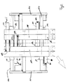
- the rectangular intermediate support plate 1, which has a central recess 100, can be seen. The lifting and transport process can be observed through them.
- the intermediate support plate 1 has a horizontal upper and lower leg 2, 4 and two vertical legs 3 and 5. The upper leg 2 can be omitted. Then the intermediate support plate 1 has a U-shaped shape.
- Bearings 6o, 7o, 8o, 9o are provided in the corner areas of the intermediate support plate, more precisely in the upper corners and slightly above the lower corners.
- the lower bearings 70.80 attached slightly above the lower corners can also be moved entirely into the lower corners. However, in terms of operational safety, it is more economical to place the bearings mentioned higher by the center distance of the double axles.
- the bearings are designed as plain bearings.
- Double-axis systems 10-13 are guided in the plain bearings 6o to 9o.
- Each double-axis system has two parallel rotary axes 10o, 10u, 110 ..., 13o, 13u aligned with one another.
- Two parallel support arms 20a, 20i and 21a, 21i are arranged on two superimposed double-axis systems, ie 10 and 11, or 12 and 13.
- the support arms mentioned each have a vertical strut 60a, 60i or 61a, 61i, on which a gripper is arranged.
- 1 shows, by way of example, tines 50 arranged at the lower end of the vertical struts and pointing forward in the horizontal direction (protruding from the paper plane).
- side grippers 51 can also be arranged on the vertical struts, but not at the lower end of the support arms 60a, 60i, 61a, 61i, but are arranged at the center or the entire vertical extent thereof.
- the double axis systems 10, 11, 12, 13 are explained in more detail using a double axis system 11 as an example.
- the other double-axis systems 10, 12, 13 of FIG. 1 have the same configuration, which is why the explanations also apply to them.
- the two parallel rotary axes 11o, 11u which are aligned horizontally, that is to say do not have any lateral offset relative to one another in the horizontal direction, have already been mentioned.
- the ends lying one above the other are connected to one another.
- the connection in the outer area takes place via a terminating piece 71, which is expediently designed to be rectangular or oval.
- the two parallel double axes are connected to the inner vertical strut 60i of the support arm 20i. This can be done by reducing the axle diameter and appropriate holes in the support arm and counter nuts.
- the purpose of the mutual connection of the double axes 11o, 11u is that the two horizontal axes cannot be moved relative to one another. On the other hand, they can be moved together via the bearing 7o attached to the intermediate carrier plate 1.
- the mentioned bearing enables the double-axis system 11 to be displaceable by sliding the upper axis 11o.
- the lower axis carries a slide bearing 7u which does not support the axis in a laterally displaceable manner, but rather the outer support arm 20a or its vertical strut 60a. It is firmly connected to the bearing 7u or the corresponding bearing sleeve.
- the sliding displaceability of the outer vertical strut 60a by means of the bearing 7u on the axis 11u allows the displacement (sideways-outwards and sideways-inwards) of the outer support arm 20a with respect to the inner support arm 20i, which is the two ends of the double axes 11o and 11u firmly together connects. It is only common to both axes 11o and 11u - and thus also to the outer support arm 20a - horizontally displaceable sideways-outwards and sideways-inwards.
- the double-axis system 11 described is arranged four times on the intermediate support plate 1. Its description applies equally to all four modularized double axis systems 10-13.
- the two superimposed double axis systems 10 and 11 or 12 and 13 are horizontally aligned so that their ends or the end connectors 70, 71 come to lie one above the other without offset.
- the inner support arm 20i creates the coupling between the one above the other without an offset arranged double-axis systems 10 and 11.
- a respective vertical pair of double-axis systems can thus only be moved together. This applies to each vertical pair 10 and 11 or 12 and 13.
- the opposite pairs of double-axis systems 10, 13 and 11, 12 are arranged at the same height. The respective axes of the double axes are aligned horizontally.
- This alignment is achieved by attaching the bearings 6o, 9o and 7o, 8o to the intermediate carrier plate 1 at the same height.
- the same height attachment of the opposite double axis systems creates an equal deflection of the respective pairs of support arms 20i, 20a and. 21i, 21a, if these are loaded because the same lever arms are effective.
- piston-cylinder arrangements 40, 41 which converts the mentioned lateral displaceability of the outer support arms and the double-axis systems with the inner and outer support arms into a horizontal displacement.
- the piston-cylinder arrangements 40, 41 are equipped as hydraulic cylinders with inlet and outlet valves arranged on both sides, so that a back and forth movement is possible via the same piston-cylinder arrangements by means of hydraulic oil. They are each arranged on a vertical leg 3, 5 of the intermediate support plate 1 and engage with their respective other end on the respective outer vertical strut 60a, 61a of the outer support arms 20a, 21a of each pair of support arms.
- the support arms can be displaced in parallel by means of the piston-cylinder arrangement, which is explained on the basis of a workflow according to FIG. 3.
- FIG. 3 shows four diagrams which explain the forklift attachment according to FIG. 1 in different working positions.
- the upper diagram shows the truck attachment when retracted.
- the two pairs of support arms are immediately adjacent.
- Single pallets can be used can be picked up by gripping a pair of support arms (here: tines) under each half of a pallet.
- the upper right partial image shows a side view, in which the tines 50 and the vertical strut 61a are visible, forming the outer support arm 21a.
- the second image from above in the left field of FIG. 3 shows phase 1, in which the support arms 20i, 20a or 21i and 21a are moved into the spread position.
- the respective pairs of support arms In the spread position shown, the respective pairs of support arms have their maximum working distance b from one another. This applies to the left-hand and right-hand pair of support arms.
- Each pair of support arms is moved into this spread position in that the respective outer support arms 20a, 21a on the lower axes 10u, 11u, 12u, 13u are laterally displaced (outwards) by means of the piston-cylinder arrangements 40, 41 (not shown here). This can already be a working position, depending on the grid dimensions, of the goods to be transported.
- a side view is again shown, but this time with a gripper arm 51 which is attached to the vertical strut 61a. It can be used to transport loads clamped, while the aforementioned tines 50 support the loads.
- the third diagram from the top in the left field shows phase 2.
- the respectively maximally spaced support arms are shifted in pairs by means of the bearings 6o, 7o or 8o and 9o which are fixedly arranged on the intermediate support plate 1.
- the double-axis systems 10, 11 and 12, 13 arranged one above the other are moved together in parallel.
- the lower diagram shows the forklift attachment in its fully extended state (in its maximum working position).
- the inner support arms 20i, 21i are spaced apart by the distance 2a.
- adjacent pallets can be gripped even if they are not directly next to each other on the floor.
- the left-hand and right-hand pairs of support arms 20i, 20a and 21i, 21a are displaced outwards so far beyond the bearings 6o to 9o that the mentioned bearings abut directly on the inner support arms 21i, 20i.
- the force application points on the vertical struts of the support arms are at the same height.
- a different deflection of the load-bearing support arms can occur.
- maximum flexibility with regard to the pick-up width, i.e. the distance between the support arms, is achieved.
Landscapes
- Engineering & Computer Science (AREA)
- Transportation (AREA)
- Structural Engineering (AREA)
- Civil Engineering (AREA)
- Life Sciences & Earth Sciences (AREA)
- Geology (AREA)
- Mechanical Engineering (AREA)
- Forklifts And Lifting Vehicles (AREA)
- Warehouses Or Storage Devices (AREA)
Claims (11)
- Système de guidage parallèle de bras, servant au déplacement parallèle de bras porteurs sous forme de bras de levage, de serrage ou de préhension, comprenant(a) une plaque porteuse intermédiaire (1), de préférence de forme en U ou en O, qui comporte au moins une branche horizontale (2, 4) et deux branches verticales (3, 5) et peut être fixée à une plaque de levage d'un chariot élévateur ou d'un transporteur,(b) au moins deux systèmes d'axes jumelés (10, 11; 12, 13) prévus l'un au-dessus de l'autre sur une des branches verticales (3, 5) et comportant des axes jumelés (10o, 10u; 11o, 11u),(c) un bras porteur extérieur (20a, 21a) qui, par l'intermédiaire de premiers paliers (6u, 7u), est monté horizontalement coulissant sur un axe, de préférence sur l'axe inférieur (10u, 11u; 12u, 13u), des axes jumelés et(d) des seconds paliers (60, 70; 80, 90) pour le montage horizontalement coulissant, par chaque fois l'autre axe, de préférence l'axe supérieur (10o, 11o; 12o, 13o), de chacun des systèmes d'axes jumelés (10, 11; 12, 13) prévus l'un au-dessus de l'autre, par rapport à la plaque porteuse intermédiaire (1).
- Système de guidage parallèle de bras selon la revendication 1, caractérisé en ce
que les systèmes d'axes jumelés (10, 11; 12, 13) superposés sont reliés entre eux par leurs bras porteurs intérieurs (20i, 21i), lesquels sont déplaçables parallèlement aux bras porteurs extérieurs (20a, 21a), mais sont immobiles par rapport aux axes (10o, 10u; 11o, 11u; 12o, 12u; 13o, 13u) des systèmes d'axes jumelés (10, 11; 12, 13) superposés. - Système de guidage parallèle de bras selon une des revendications précédentes, caractérisé en ce(a) que chaque système d'axes jumelés (10-13) comporte deux axes jumelés étroitement voisins (10o, 10u; 11o, 11u; 12o, 12u; 13o, 13u), de préférence deux axes de section droite circulaire, qui sont orientés horizontalement et sont reliés entre eux, de préférence à leurs extrémités extérieures respectives, par une pièce de liaison terminale (70-73), pour former chaque fois une paire,(b) que les bras porteurs (20a, 20i; 21a, 21i) comportent des branches verticales ou montants (60a, 60i; 61a, 61i) qui sont orthogonaux aux axes jumelés voisins (10o, 1Ou, ...) des systèmes d'axes jumelés (10-13) supérieurs et inférieurs, dont le montant extérieur, ensemble avec les premiers paliers (6u, 7u), constitués par des paliers lisses, est déplaçable latéralement sur l'axe inférieur (10u, 11u) coordonné et dont le montant intérieur est relié fixe à tous les axes parallèles des systèmes d'axes jumelés (10, 11; 12, 13) superposés, aux extrémités intérieures de ces axes, et(c) que les bras porteurs sont pourvus de fourchons de prise (50) à l'extrémité inférieure des montants (60a, 60i; 61a, 61i), ou de tenailles (51) dans la partie médiane des montants, fourchons ou tenailles au moyen desquels des charges de différentes dimensions peuvent être saisies et transportées.
- Système de guidage parallèle de bras selon une des revendications précédentes, caractérisé en ce(a) que deux systèmes d'axes jumelés (10, 11; 12, 13) sont prévus l'un au-dessus de l'autre sur chaque branche verticale (3, 5) de la plaque porteuse intermédiaire (1), ayant une forme en O ou rectangulaire avec un évidement central (100), systèmes superposés qui forment chaque fois une paire et portent chaque fois une paire de bras porteurs guidés l'un à côté de l'autre et constituant respectivement un bras porteur intérieur et un bras porteur extérieur (20a, 20i; 21a, 21i) et(b) qu'un vérin (40, 41) est prévu chaque fois entre le bras porteur extérieur (20a, 21a) et la plaque porteuse intermédiaire (1), vérin qui déplace latéralement, pour la rétraction et l'extension, le bras porteur extérieur (20a, 21a) par rapport au bras porteur intérieur (20i, 21i) associé, ou qui déplace chaque fois ensemble, pour la rétraction et l'extension, les bras porteurs extérieur et intérieur (20i, 21i; 20a, 21a) associés par coulissement dans les seconds paliers (60, 70, 80, 90) montés sur la plaque porteuse intermédiaire (1).
- Système de guidage parallèle de bras selon une des revendications précédentes, caractérisé en ce(a) que les seconds paliers (60, 70, 80, 90) sont placés dans les zones d'angle de la plaque porteuse intermédiaire (1), laquelle est réalisée sous la forme d'un rectangle dont les grands côtés sont orientés horizontalement et avec un évidement carré (100) au centre, les branches latérales (3-5) présentant une largeur prédéterminée correspondant à la charge à supporter et portant les seconds paliers (60, ...90) dans lesquels les systèmes d'axes jumelés (10-13) peuvent coulisser horizontalement et(b) que les dimensions extérieures des flasques, lesquels reçoivent les coussinets des premiers et seconds paliers lisses (6o, 6u, ...9o, 9u), sont mutuellement accordées de manière que ces flasques, ayant de préférence une forme en S de sens contraires, puissent glisser l'un devant l'autre sans se toucher dans un système d'axes jumelés (10-13).
- Procédé opératoire pour le réglage latéral de bras porteurs parallèles, de préférence pour un système de guidage parallèle de bras selon une des revendications précédentes, selon lequel:(a) deux bras porteurs parallèles, constituant respectivement un bras porteur intérieur et un bras porteur extérieur (20a, 20i; 21a, 21i), sont déplacés à l'aide d'au moins deux systèmes d'axes jumelés (10, 11; 12, 13);(b) les deux axes (10o, 10u; 11o, 11u) de chaque système d'axes jumelés (10, 11; 12, 13) ne peuvent pas effectuer de mouvements relatifs de sens contraires;(c1) le bras porteur intérieur (20i, 21i) est déplacé latéralement sur l'axe inférieur (10u, 11u) des systèmes d'axes jumelés (10, 11) et(c2) chaque système d'axes jumelés (10, 11; 12, 13) est lui-même déplacé latéralement grâce au montage coulissant de l'axe supérieur (10o, 11o) de chaque système d'axes jumelés (10, 11).
- Procédé opératoire pour le réglage latéral de bras porteurs parallèles selon la revendication 6, selon lequel:(a) les deux bras porteurs parallèles (20i, 20a; 21i, 21a) sont placés, à la position de base, à proximité l'un de l'autre sur les systèmes d'axes jumelés (10, 11; 12, 13), systèmes qui sont au nombre d'au moins deux et sont superposés sans décalage latéral,(b) le bras porteur extérieur (20a, 21a) est déplacé latéralement vers l'extérieur, sur l'axe coordonné (10u, 11u; 13u, 12u) des systèmes d'axes jumelés (10, 11; 12, 13), à une position écartée dans laquelle les bras porteurs intérieur et extérieur (20a, 20i; 21a, 21i) présentent un écartement (b) qui correspond essentiellement à la longueur de tous les axes, de même longueur, de tous les systèmes d'axes jumelés (10, 11, 12, 13),(c) le bras porteur intérieur (20i, 21i), relié rigidement à tous les axes (10o, 10u; 11o, 11u; 12o, 12u; 13o, 13u) des systèmes superposés d'axes jumelés (10, 11; 12, 13) coordonnés, est déplacé latéralement vers l'extérieur, ensemble avec le bras porteur extérieur (20a, 21a), à une position de travail, avec maintien sans changement, pendant le déplacement, de l'écartement (b) entre les bras porteurs intérieur et extérieur (20a, 20i; 21a, 21i).
- Procédé opératoire pour le réglage latéral de bras porteurs selon une des revendications de procédé précédentes, caractérisé en ce
que le déplacement latéralement vers l'extérieur des deux bras porteurs (20i, 20a; 21i, 21a) s'effectue à l'aide de paliers (60, 70; 80, 90) pour le montage coulissant de l'axe supérieur (10o, 11o; 12o, 13o) des systèmes d'axes jumelés (10 à13) sur une plaque porteuse intermédiaire (1), le déplacement s'effectuant jusqu'à une position de travail correspondant à la dimension de l'objet formant la charge à porter. - Procédé opératoire pour le réglage latéral de bras porteurs selon une des revendications précédentes, caractérisé en ce
que, lors de l'extension du bras porteur extérieur (20a, 21a), un déplacement latéral du bras porteur intérieur, commençant déjà par son mouvement d'extension, est empêché par un dispositif de compensation, constitué de préférence par un ressort pneumatique. - Procédé opératoire pour le réglage latéral de bras porteurs selon une des revendications de procédé précédentes ou sur un système de guidage parallèle de bras selon la revendication 1, procédé selon lequel:(a) deux bras porteurs parallèles (20a, 20i) sont guidés sur des systèmes d'axes jumelés (10, 11) disposés sans décalage l'un au-dessus de l'autre,(b) deux autres bras porteurs parallèles (21a, 21i) sont guidés sur deux autres systèmes d'axes jumelés (13, 12) disposés sans décalage l'un au-dessus de l'autre et(c) les deux paires de bras porteurs parallèles (20a, 2Oi; 21a, 21i) sont juxtaposées par leurs deux systèmes d'axes jumelés (10, 11; 12, 13) respectifs sur la plaque porteuse intermédiaire (1), selon une disposition dans laquelle les axes des systèmes d'axes jumelés supérieurs et inférieurs (10, 13; 11, 12) qui se font face, sont alignés horizontalement.
- Procédé opératoire pour le réglage latéral de bras porteurs selon une des revendications de procédé précédentes ou sur un système de guidage parallèle de bras selon la revendication 1, procédé selon lequel une paire de bras porteurs (20a, 20i) et l'autre paire de bras porteurs (21a, 21i) sont latéralement déplacées, indépendamment l'une de l'autre, sur leurs systèmes superposés respectifs d'axes jumelés (12, 13; 10, 11), de manière que les demi-structures symétriques portant les axes jumelés soient entièrement découplées mécaniquement l'une de l'autre.
Applications Claiming Priority (2)
| Application Number | Priority Date | Filing Date | Title |
|---|---|---|---|
| DE4136218 | 1991-11-02 | ||
| DE4136218A DE4136218A1 (de) | 1991-11-02 | 1991-11-02 | Parallel-armfuehrungssystem und arbeitsverfahren zur seitenverstellung von parallelen tragarmen |
Publications (2)
| Publication Number | Publication Date |
|---|---|
| EP0540931A1 EP0540931A1 (fr) | 1993-05-12 |
| EP0540931B1 true EP0540931B1 (fr) | 1995-03-15 |
Family
ID=6444017
Family Applications (1)
| Application Number | Title | Priority Date | Filing Date |
|---|---|---|---|
| EP92117879A Expired - Lifetime EP0540931B1 (fr) | 1991-11-02 | 1992-10-20 | Système de guidage parallèle de fourches et procédé pour le déplacement latéral des fourches parallèles |
Country Status (4)
| Country | Link |
|---|---|
| EP (1) | EP0540931B1 (fr) |
| AT (1) | ATE119854T1 (fr) |
| DE (2) | DE4136218A1 (fr) |
| DK (1) | DK0540931T3 (fr) |
Families Citing this family (4)
| Publication number | Priority date | Publication date | Assignee | Title |
|---|---|---|---|---|
| DE4321446C2 (de) * | 1993-06-29 | 1996-02-15 | Meyer Hans H Gmbh | Anbaugerät insbesondere für verfahrbare Stapler mit seitenverschiebbaren Gabeln |
| FR2791049B1 (fr) | 1999-03-19 | 2001-06-01 | Sambron | Porte equipement pour engin de levage, mat d'un engin de levage comprenant un tel porte equipement et engin de levage tel que chariot a fourches pourvu dudit mat |
| DE102005060946A1 (de) * | 2005-12-20 | 2007-06-28 | Gämmerler AG | Stapelgreifer |
| IT201800000789A1 (it) * | 2018-01-12 | 2019-07-12 | Scm Group Spa | Sistema di magazzino automatizzato per pannelli e simili ed impianto dotato di tale sistema di magazzino automatizzato. |
Family Cites Families (5)
| Publication number | Priority date | Publication date | Assignee | Title |
|---|---|---|---|---|
| DE3301595C2 (de) * | 1983-01-19 | 1985-01-31 | Hans H. Meyer GmbH Maschinenbau, 3320 Salzgitter | Anbaugerät für verfahrbare Stapler in der Form eines Zinkenverstellgerätes mit Seitenschub und vier Zinken |
| DE3400916A1 (de) * | 1984-01-12 | 1985-07-25 | Schulte-Henke GmbH, 5778 Meschede | Zinken-anbaugeraet fuer verfahrbare stapler |
| DE3515524C2 (de) * | 1985-04-30 | 1994-12-15 | Kaup Gmbh & Co Kg | Vorbaugerät für einen Hublader, vorzugsweise Gabelstapler |
| DE3639933A1 (de) * | 1986-11-22 | 1988-06-01 | Kaup Gmbh & Co Kg | Vorbaugeraet mit zwei mittels eines antriebes verschiebbaren gabeln |
| DE8815272U1 (de) * | 1988-12-08 | 1989-02-09 | Durwen Maschinenbau GmbH, 5472 Plaidt | Fahrbares Fördergerät, insbesondere Gabelstapler, mit einer Zinkenverstellvorrichtung |
-
1991
- 1991-11-02 DE DE4136218A patent/DE4136218A1/de not_active Withdrawn
-
1992
- 1992-10-20 AT AT92117879T patent/ATE119854T1/de not_active IP Right Cessation
- 1992-10-20 DK DK92117879.4T patent/DK0540931T3/da active
- 1992-10-20 DE DE59201659T patent/DE59201659D1/de not_active Expired - Fee Related
- 1992-10-20 EP EP92117879A patent/EP0540931B1/fr not_active Expired - Lifetime
Also Published As
| Publication number | Publication date |
|---|---|
| EP0540931A1 (fr) | 1993-05-12 |
| DE4136218A1 (de) | 1993-05-06 |
| DE59201659D1 (de) | 1995-04-20 |
| DK0540931T3 (da) | 1995-05-29 |
| ATE119854T1 (de) | 1995-04-15 |
Similar Documents
| Publication | Publication Date | Title |
|---|---|---|
| EP0116281B1 (fr) | Accessoire pour chariot élévateur en forme d'un régleur de fourche avec poussée latérale et quatre fourches | |
| DE69105896T2 (de) | Verstellgerät für mehrere Gabelzinkenpaare. | |
| AT407129B (de) | Vorrichtung zum wechseln von spannrahmen in einer bearbeitungsstation | |
| EP2598428A1 (fr) | Dispositif pour accueillir des charges | |
| EP0540931B1 (fr) | Système de guidage parallèle de fourches et procédé pour le déplacement latéral des fourches parallèles | |
| DE2949047A1 (de) | Teleskop-hubmast fuer ein fahrzeug mit motorantrieb. | |
| EP0556562B1 (fr) | Ligne de presses de transfert | |
| EP0355668B1 (fr) | Appareil de déplacement des fourches d'un chariot élévateur | |
| DE3420005A1 (de) | Gabelzinkenverstellgeraet fuer einen gabelstapler | |
| EP1995204A1 (fr) | Dispositif de réglage en longueur d'un palonnier | |
| DE3639933A1 (de) | Vorbaugeraet mit zwei mittels eines antriebes verschiebbaren gabeln | |
| DE10220202A1 (de) | Lasthandhabungsvorrichtung für ein Flurförderzeug | |
| DE202020101753U1 (de) | Wechselvorrichtung für einen Wechsel von wenigstens zwei Werkstückauflagen für eine Bearbeitungsmaschine | |
| EP1340709A1 (fr) | Installation de transport pour transporter des éléments de structure | |
| DE10154842C2 (de) | Anbaugerät für Hubmasten, insbesondere für Hubstaplerfahrzeuge | |
| EP0631975B1 (fr) | Accessoire en particulier pour chariot élévateur | |
| DE4129139C1 (fr) | ||
| EP1378480A1 (fr) | Véhicule de transport pour transporter des éléments de structure | |
| DE69923104T2 (de) | Mittel zum Verstellen von der horizontalen Basisachse von Vorrichtungen für Gabelhubwagen oder ähnlichem | |
| EP0216950A1 (fr) | Porte-charge pour transporteur aérien | |
| EP0591967B1 (fr) | Dispositif pour la manutention de charges | |
| DE4117753A1 (de) | Anbaugeraet fuer verfahrbare stapler in form eines zinken- oder klammerverstellgeraetes | |
| WO2025180677A1 (fr) | Dispositif de stockage et de récupération avec fonction de compensation d'angle pour un entrepôt à hauts rayonnages | |
| EP1272405A2 (fr) | Dispositif pour transporter des pieces plates de maniere suspendue | |
| DE102024003443A1 (de) | Verfahrbare Teleskoptische an einem Lastaufnahmemittel |
Legal Events
| Date | Code | Title | Description |
|---|---|---|---|
| PUAI | Public reference made under article 153(3) epc to a published international application that has entered the european phase |
Free format text: ORIGINAL CODE: 0009012 |
|
| AK | Designated contracting states |
Kind code of ref document: A1 Designated state(s): AT CH DE DK FR GB LI NL SE |
|
| 17P | Request for examination filed |
Effective date: 19930515 |
|
| 17Q | First examination report despatched |
Effective date: 19940505 |
|
| GRAA | (expected) grant |
Free format text: ORIGINAL CODE: 0009210 |
|
| AK | Designated contracting states |
Kind code of ref document: B1 Designated state(s): AT CH DE DK FR GB LI NL SE |
|
| REF | Corresponds to: |
Ref document number: 119854 Country of ref document: AT Date of ref document: 19950415 Kind code of ref document: T |
|
| GBT | Gb: translation of ep patent filed (gb section 77(6)(a)/1977) |
Effective date: 19950314 |
|
| REF | Corresponds to: |
Ref document number: 59201659 Country of ref document: DE Date of ref document: 19950420 |
|
| REG | Reference to a national code |
Ref country code: DK Ref legal event code: T3 |
|
| ET | Fr: translation filed | ||
| PLBE | No opposition filed within time limit |
Free format text: ORIGINAL CODE: 0009261 |
|
| STAA | Information on the status of an ep patent application or granted ep patent |
Free format text: STATUS: NO OPPOSITION FILED WITHIN TIME LIMIT |
|
| 26N | No opposition filed | ||
| PGFP | Annual fee paid to national office [announced via postgrant information from national office to epo] |
Ref country code: DK Payment date: 19960927 Year of fee payment: 5 |
|
| PGFP | Annual fee paid to national office [announced via postgrant information from national office to epo] |
Ref country code: FR Payment date: 19960930 Year of fee payment: 5 |
|
| PGFP | Annual fee paid to national office [announced via postgrant information from national office to epo] |
Ref country code: GB Payment date: 19961007 Year of fee payment: 5 |
|
| PGFP | Annual fee paid to national office [announced via postgrant information from national office to epo] |
Ref country code: SE Payment date: 19961022 Year of fee payment: 5 |
|
| PGFP | Annual fee paid to national office [announced via postgrant information from national office to epo] |
Ref country code: CH Payment date: 19961028 Year of fee payment: 5 |
|
| PGFP | Annual fee paid to national office [announced via postgrant information from national office to epo] |
Ref country code: AT Payment date: 19961030 Year of fee payment: 5 |
|
| PGFP | Annual fee paid to national office [announced via postgrant information from national office to epo] |
Ref country code: NL Payment date: 19961031 Year of fee payment: 5 |
|
| PGFP | Annual fee paid to national office [announced via postgrant information from national office to epo] |
Ref country code: DE Payment date: 19961205 Year of fee payment: 5 |
|
| PG25 | Lapsed in a contracting state [announced via postgrant information from national office to epo] |
Ref country code: GB Free format text: LAPSE BECAUSE OF NON-PAYMENT OF DUE FEES Effective date: 19971020 Ref country code: AT Free format text: LAPSE BECAUSE OF NON-PAYMENT OF DUE FEES Effective date: 19971020 |
|
| REG | Reference to a national code |
Ref country code: DK Ref legal event code: EBP |
|
| PG25 | Lapsed in a contracting state [announced via postgrant information from national office to epo] |
Ref country code: SE Free format text: LAPSE BECAUSE OF NON-PAYMENT OF DUE FEES Effective date: 19971021 |
|
| PG25 | Lapsed in a contracting state [announced via postgrant information from national office to epo] |
Ref country code: LI Free format text: LAPSE BECAUSE OF NON-PAYMENT OF DUE FEES Effective date: 19971031 Ref country code: FR Free format text: THE PATENT HAS BEEN ANNULLED BY A DECISION OF A NATIONAL AUTHORITY Effective date: 19971031 Ref country code: DK Free format text: LAPSE BECAUSE OF NON-PAYMENT OF DUE FEES Effective date: 19971031 Ref country code: CH Free format text: LAPSE BECAUSE OF NON-PAYMENT OF DUE FEES Effective date: 19971031 |
|
| PG25 | Lapsed in a contracting state [announced via postgrant information from national office to epo] |
Ref country code: NL Free format text: LAPSE BECAUSE OF NON-PAYMENT OF DUE FEES Effective date: 19980501 |
|
| GBPC | Gb: european patent ceased through non-payment of renewal fee |
Effective date: 19971020 |
|
| REG | Reference to a national code |
Ref country code: CH Ref legal event code: PL |
|
| NLV4 | Nl: lapsed or anulled due to non-payment of the annual fee |
Effective date: 19980501 |
|
| PG25 | Lapsed in a contracting state [announced via postgrant information from national office to epo] |
Ref country code: DE Free format text: LAPSE BECAUSE OF NON-PAYMENT OF DUE FEES Effective date: 19980701 |
|
| EUG | Se: european patent has lapsed |
Ref document number: 92117879.4 |
|
| REG | Reference to a national code |
Ref country code: FR Ref legal event code: ST |