EP0541092A2 - Caméra vidéo munie d'un mécanisme de zoom optique et d'un stabilisateur d'image - Google Patents
Caméra vidéo munie d'un mécanisme de zoom optique et d'un stabilisateur d'image Download PDFInfo
- Publication number
- EP0541092A2 EP0541092A2 EP92118979A EP92118979A EP0541092A2 EP 0541092 A2 EP0541092 A2 EP 0541092A2 EP 92118979 A EP92118979 A EP 92118979A EP 92118979 A EP92118979 A EP 92118979A EP 0541092 A2 EP0541092 A2 EP 0541092A2
- Authority
- EP
- European Patent Office
- Prior art keywords
- magnification
- zoom magnification
- stabilization
- electronic zoom
- mode
- Prior art date
- Legal status (The legal status is an assumption and is not a legal conclusion. Google has not performed a legal analysis and makes no representation as to the accuracy of the status listed.)
- Granted
Links
- 230000003287 optical effect Effects 0.000 title claims abstract description 37
- 230000007246 mechanism Effects 0.000 title abstract description 10
- 239000003381 stabilizer Substances 0.000 title description 2
- 230000006641 stabilisation Effects 0.000 claims abstract description 67
- 238000011105 stabilization Methods 0.000 claims abstract description 67
- 230000007423 decrease Effects 0.000 claims abstract description 6
- 230000008859 change Effects 0.000 abstract description 17
- 238000000034 method Methods 0.000 description 8
- 230000000994 depressogenic effect Effects 0.000 description 6
- 238000001514 detection method Methods 0.000 description 6
- 238000005070 sampling Methods 0.000 description 6
- 230000008569 process Effects 0.000 description 5
- 230000003247 decreasing effect Effects 0.000 description 4
- 238000010586 diagram Methods 0.000 description 2
- 230000001052 transient effect Effects 0.000 description 2
- 238000009825 accumulation Methods 0.000 description 1
- 230000006870 function Effects 0.000 description 1
- 230000006872 improvement Effects 0.000 description 1
- 230000009467 reduction Effects 0.000 description 1
Images


Classifications
-
- G—PHYSICS
- G02—OPTICS
- G02B—OPTICAL ELEMENTS, SYSTEMS OR APPARATUS
- G02B7/00—Mountings, adjusting means, or light-tight connections, for optical elements
- G02B7/02—Mountings, adjusting means, or light-tight connections, for optical elements for lenses
- G02B7/04—Mountings, adjusting means, or light-tight connections, for optical elements for lenses with mechanism for focusing or varying magnification
- G02B7/10—Mountings, adjusting means, or light-tight connections, for optical elements for lenses with mechanism for focusing or varying magnification by relative axial movement of several lenses, e.g. of varifocal objective lens
- G02B7/102—Mountings, adjusting means, or light-tight connections, for optical elements for lenses with mechanism for focusing or varying magnification by relative axial movement of several lenses, e.g. of varifocal objective lens controlled by a microcomputer
-
- H—ELECTRICITY
- H04—ELECTRIC COMMUNICATION TECHNIQUE
- H04N—PICTORIAL COMMUNICATION, e.g. TELEVISION
- H04N23/00—Cameras or camera modules comprising electronic image sensors; Control thereof
- H04N23/60—Control of cameras or camera modules
- H04N23/68—Control of cameras or camera modules for stable pick-up of the scene, e.g. compensating for camera body vibrations
- H04N23/681—Motion detection
- H04N23/6811—Motion detection based on the image signal
-
- H—ELECTRICITY
- H04—ELECTRIC COMMUNICATION TECHNIQUE
- H04N—PICTORIAL COMMUNICATION, e.g. TELEVISION
- H04N23/00—Cameras or camera modules comprising electronic image sensors; Control thereof
- H04N23/60—Control of cameras or camera modules
- H04N23/68—Control of cameras or camera modules for stable pick-up of the scene, e.g. compensating for camera body vibrations
- H04N23/682—Vibration or motion blur correction
- H04N23/683—Vibration or motion blur correction performed by a processor, e.g. controlling the readout of an image memory
Definitions
- the present invention relates to a video camera. More specifically, the present invention relates to a compact video camera having an optical zoom mechanism, and a picture stabilizer which utilizes an electronic zoom mechanism.
- a stabilization mode that is set by turning the stabilization switch on
- a video signal is extracted from an image extracting area narrower than the image field.
- a stabilization releasing mode that is set by turning the stabilization switch off
- a video signal is outputted from a whole image field. Therefore, when the stabilization mode is changed to the stabilization releasing mode, a view angle suddenly becomes large, and therefore, a subject becomes small suddenly.
- the stabilization releasing mode is changed to the stabilization mode, since the view angle suddenly becomes small, a subject becomes large suddenly.
- a principal object of the present invention is to provide a novel video camera.
- Another object of the present invention is to provide a video camera in which it is possible to prevent a view angle from being suddenly changed in changing a mode.
- a video camera comprises an optical zoom means having a controllable optical zoom magnification and an electronic zoom means having a controllable electronic zoom magnification.
- first magnification changing means gradually changes the electronic zoom magnification of the electronic zoom means
- second magnification changing means gradually changes the optical zoom magnification of the optical zoom means in a direction that is opposite to a direction toward which the electronic zoom magnification is changed in accordance with the electronic zoom magnification that is changed by the first magnification changing means.
- a sudden change of a view angle due to a change of the electronic zoom magnification at a timing of mode change can be suppressed. Therefore, even if the mode is changed, no sudden change occurs in a size of a subject, and therefore, no stiff feeling occurs.
- a video camera 10 of a preferred embodiment shown in Figure 1 includes a solid-state image sensing device 12 such as a CCD (Charge-Coupled Device) which converts an optical signal being inputted from a subject (not shown) through optical zoom mechanism including lens (not shown) into an electric signal.
- the electric signal from the solid-state image sensing device 12 is inputted to a camera circuit 16.
- the camera circuit 16 includes a sample-hold circuit by which the electric signal from the solid-state image sensing device is sampled and held. A level of the electric signal thus sampled and held is adjusted by an AGC (Automatic Gain Control), and synchronization signals are added to the electric signal by a synchronization signal adding circuit (not shown).
- AGC Automatic Gain Control
- the camera circuit converts the electric signal from the solid-state image sensing device 12 into an analog video signal.
- the analog video signal is further converted into a digital video signal by an A/D converter 18.
- the digital video signal is applied to a motion detecting circuit 20.
- the motion detecting circuit 20 for example, an LSI "L7A0948" manufactured by Sanyo Electric Co., Ltd. who is an assignee of the present invention may be utilized.
- the digital video signal is written into a field memory 24 field by field.
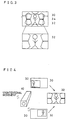
- the motion detecting circuit 20 evaluates correlative values, for each of respective blocks A, B, C and D shown in Figure 2A by utilizing a well-known representative point matching method.
- an image field 30 is contained in an image sensing area that is formed by the sold-state image sensing device 12.
- each of the blocks includes a predetermined number (in Figure 2A, "16") of detection areas.
- a detection area is composed of a plurality of sampling points out of which a representative point is determined.
- the motion detecting circuit 20 calculates the correlative values on the basis of luminance levels of respective sampling points.
- the motion detecting circuit 20 absolute values of differences between luminance level of the respective sampling points within each of the detection areas at a current field or frame and a luminance level of the representative point within the same detection area at a last filed or frame. That is, correlative values of the luminance levels of the respective sampling points with respect to the representative point in the same detection area are calculated. The correlative values of the luminance levels are accumulated for each of the sampling points having the same deviation in position with respect to the representative point, i.e. having the same positional relationship with respect to the representative point.
- a sampling point having a minimum accumulated value is a point having a highest correlation degree. Positional data and correlative values (accumulated values) of the above described point and other four (4) points around the point.
- the positional data and correlative values data from the motion detecting circuit 20 are applied to a microcomputer 26.
- a microcomputer 26 on the basis of the positional data and the correlative values data, an average motion vector of a whole image field 30 ( Figure 2) is calculated according to flowcharts described later in detail.
- Data of the average motion vector is applied to the memory control circuit 22 which determines a start address for reading the field memory 24, and therefore, the digital video signal is read-out from the field memory 24.
- the memory control circuit 22 moves an image extracting area 32 ( Figure 3 or 4) formed by the digital video signal stored in the field memory 24 according to the average motion vector that is calculated by the microcomputer 26.
- the electronic zooming circuit 28 defines the image extracting area 32 wherein an image is enlarged according to a zoom magnification with respect to the image field 30.
- a position of the image extracting area 32 can be freely moved within a range of the image field 30 by changing a start address for reading-out the digital video signal from the field memory 24. Then, in order to obtain a video signal for a whole area of the image field 30 on the basis of the digital video signal extracted from the image extracting area 32, an image is enlarged by utilizing an internal interpolation on the basis of the digital video signal read-out from the field memory 24.
- an unintentional movement occurs in the video camera 10 as shown in Figure 4 according to a vibration of a hand of a person who operates the video camera, an image from the video camera is blurred, and resulting in a case where a subject person exists in a left-lower portion within the image field 30 (shown at an upper portion in Figure 4) or a case where a subject person exists at a right-upper portion within the image field (shown at a lower portion in Figure 4). Therefore, by moving the image extracting area 32 at every field or frame according to the average motion vector that is calculated by the microcomputer 26, as shown at a right portion in Figure 4, the subject person can be just positioned in the image extracting area 32.
- the digital video signal thus outputted from the electronic zoom circuit 28 is converted into an analog signal by a D/A converter 36 so as to be outputted from an output terminal 38.
- the motion detecting circuit 20 shown in Figure 1 includes an input end 40 which receives the digital video signal from the A/D converter 18.
- the digital video signal inputted to the input end 40 is applied to the representative point memory 44 and a subtracting circuit 46, respectively, through a filter 42.
- the filter 42 is a kind of digital low-pass filter which is utilized for improvement of an S/N ratio so as to secure a significant detection accuracy with a lesser number of representative points.
- the representative point memory 44 stores positional data and luminance data of a plurality of representative points within each of the respective blocks A-D shown in Figure 2.
- the subtracting circuit 46 executes subtracting operations of the luminance data read-out from the representative point memory 44 of the representative point and another points or pixels surrounding the representative point, and applies a subtracted result to an accumulating and adding circuit 48.
- the accumulating and adding circuit 48 executes an accumulation and addition of the subtracted results by the subtracting circuit 46 of the same position or pixel in the same block so as to output correlative values data.
- the correlative values data is applied to an arithmetic operation circuit 50 which evaluates a minimum correlative value and calculates an average correlative value for each of the blocks A-D, and evaluates positional data of the pixel having the minimum correlative value.
- Data of the minimum correlative value, average correlative value and positions thus obtained by the arithmetic operation circuit 50 are applied to the above described microcomputer 26 from an output end 52.
- arithmetic operations for the correlative values can be performed by the above described LSI "L7A0948".
- a microcomputer 26 has a suitable memory 54, and to the microcomputer 26, a switch input and a key input from a stabilization switch 56 and a zoom key 58. Then, when the stabilization switch 56 is turned-on, the microcomputer 26 performs a picture stabilization by utilizing the above described electronic zoom circuit 28 in a manner that described in co-pending United States Patent Application serial No. filed on October 19, 1992, for example.
- the zoom key 58 includes a zoom up key 58u for making a zoom magnification large and a zoom down key 58d for making a zoom magnification small. If the zoom up key 58u is depressed, the microcomputer 26, first, controls a zoom motor 60 so as to perform a zoom-up operation by utilizing the optical zoom mechanism 14, and when an optical zoom magnification reaches a limit thereof, succeedingly, the microcomputer 26 magnifies an image to a zoom magnification set by the zoom up key 58u by utilizing the electronic zoom circuit 28. When the electronic zoom circuit 28 is used, the microcomputer 26 gradually increase a magnification for the electronic zoom in association with a time that the zoom up key 58u is depressed. That is, the microcomputer gradually reduces the image extracting area 32 ( Figure 3). If the zoom down key 58d is depressed, an operation in reverse to the above described operation is performed.
- the microcomputer 26 fixedly sets an electronic zoom magnification to "1.2".
- an electronic zoom magnification can be arbitrarily changed according to a specification of a video camera.
- the microcomputer 26 determines whether the electronic zoom magnification stored in the memory 54 is larger than "1.2" that is a magnification for a picture stabilization. If "YES" is determined in the step S5, a process immediately proceeds to a picture stabilization mode.
- step S5 since it is impossible to perform the picture stabilization at hat electronic zoom magnification, the microcomputer 26 must set the electronic zoom magnification to "1.2". Then, if a vertical synchronization signal is detected in a step S7, the microcomputer 26, in a next step S9, calculates an electronic zoom magnification (Me) according to the following equation (1) and sets the same.
- Me electronic zoom magnification
- the microcomputer 26 detects that the stabilization switch 56 is turned-off in a step S21, the microcomputer 26, in a next step S23, determines whether the electronic zoom magnification at a timing when the picture stabilization mode is set, that is, the electronic zoom magnification (Me) at a timing when the stabilization switch 56 is previously turned-on is larger than "1.2". If "YES" is determined in the step S23, a process immediately proceeds to the stabilization releasing mode.
- step S23 it is necessary to return the electronic zoom magnification to an electronic zoom magnification at a timing when the stabilization switch 56 is previously turned-on. Then, if a vertical synchronization signal Vsync is detected in a step S25, the microcomputer 26, in a next step S27, calculates an electronic zoom magnification (Me) according to the following equation (3) and sets the same.
- the microcomputer 26 gradually changes the optical zoom magnification in association with the electronic zoom magnification so that a sudden change of a view angle due to a sudden change of the electronic zoom magnification according to a mode change between a stabilization mode and the stabilization releasing mode can be suppressed. Therefore, according to the embodiment shown, an operation as shown in Figure 8 can be performed.
- a line A denotes a change of the electronic zoom magnification
- a line B denotes a change the optical zoom magnification.
- the stabilization mode is performed after a subject is zoomed-up by gradually deducing the image extracting area 32 ( Figure 3), that is, by gradually increasing the electronic zoom magnification in a transient period from a timing T0 to a timing T1 of Figure 8. At this time, the optical zoom magnification is gradually decreased, whereby a sudden change of a view angle in proceeding to the stabilization mode is prevented.
- the microcomputer 26 If the stabilization mode is changed into the stabilization releasing mode by turning-off the stabilization switch 56, the microcomputer 26 gradually enlarges the image extracting area 32, that is, gradually decreases the electronic zoom magnification in a transient period from a timing T2 to a timing T3 of Figure 8, and thereafter, the microcomputer 26 performs an operation of the stabilization releasing mode. At this time, since the optical zoom magnification is gradually increased, a sudden change of a view angle in proceeding to the stabilization releasing mode is effectively prevented.
- the zoom down key 58d of the zoom key 58 is depressed during a time from a timing T4 to a timing T5 of Figure 8, during a period when the zoom down key 58d is depressed, the microcomputer 26 gradually decreases the zoom magnification of the optical zoom mechanism 14 by controlling the zoom motor 60.
- the microcomputer 26 controls the zoom motor 60 so as to gradually increase the zoom magnification of the optical zoom mechanism 14.
- the microcomputer 26 enables the electronic zoom function, and therefore, the image extracting area 32 is reduced. That is, the electronic zoom magnification is increased, and thus, the electronic zoom magnification becomes more than "1.2".
- the stabilization switch 56 is turned-on at a timing T9 of Figure 8
- the microcomputer 26 does not further increase the electronic zoom magnification, and continues the picture stabilization operation.
- the stabilization switch 56 is turned-off at a timing T10 of Figure 8, since the electronic zoom magnification at that time is more than "1.2", an operation of the stabilization releasing mode is continuously performed.
- the electronic zoom magnification for the stabilization mode is fixedly set as "1.2".
- a specific value of the electronic zoom magnification for the stabilization mode is not limited to "1.2", and such an electronic zoom magnification may be variably set according to an operation of the operator.
Landscapes
- Engineering & Computer Science (AREA)
- Multimedia (AREA)
- Signal Processing (AREA)
- Physics & Mathematics (AREA)
- General Engineering & Computer Science (AREA)
- General Physics & Mathematics (AREA)
- Optics & Photonics (AREA)
- Lens Barrels (AREA)
- Studio Devices (AREA)
- Compression Or Coding Systems Of Tv Signals (AREA)
- Adjustment Of Camera Lenses (AREA)
Applications Claiming Priority (2)
| Application Number | Priority Date | Filing Date | Title |
|---|---|---|---|
| JP288817/91 | 1991-11-05 | ||
| JP28881791A JPH05130484A (ja) | 1991-11-05 | 1991-11-05 | 手ブレ補正機能付きビデオカメラの画角補正回路 |
Publications (3)
| Publication Number | Publication Date |
|---|---|
| EP0541092A2 true EP0541092A2 (fr) | 1993-05-12 |
| EP0541092A3 EP0541092A3 (en) | 1993-08-11 |
| EP0541092B1 EP0541092B1 (fr) | 1996-04-24 |
Family
ID=17735126
Family Applications (1)
| Application Number | Title | Priority Date | Filing Date |
|---|---|---|---|
| EP19920118979 Expired - Lifetime EP0541092B1 (fr) | 1991-11-05 | 1992-11-05 | Caméra vidéo munie d'un mécanisme de zoom optique et d'un stabilisateur d'image |
Country Status (4)
| Country | Link |
|---|---|
| US (1) | US6396538B1 (fr) |
| EP (1) | EP0541092B1 (fr) |
| JP (1) | JPH05130484A (fr) |
| DE (1) | DE69210174T2 (fr) |
Cited By (14)
| Publication number | Priority date | Publication date | Assignee | Title |
|---|---|---|---|---|
| EP0586218A1 (fr) * | 1992-09-01 | 1994-03-09 | Canon Kabushiki Kaisha | Appareil de traitement d'images |
| EP0608099A1 (fr) * | 1993-01-21 | 1994-07-27 | Sony Corporation | Caméra vidéo avec zoom électronique |
| GB2275842A (en) * | 1992-12-21 | 1994-09-07 | Gold Star Co | Automatic image stabilizing system for a camcorder |
| EP0631432A1 (fr) * | 1993-06-28 | 1994-12-28 | SANYO ELECTRIC Co., Ltd. | Caméra vidéo avec stabilisateur d'image électronique |
| EP0717561A1 (fr) * | 1994-12-16 | 1996-06-19 | SANYO ELECTRIC Co., Ltd. | Stabilisateur électronique d'image et caméra l'utilisant |
| EP0671850A3 (fr) * | 1994-03-10 | 1997-02-26 | Israel State | Méthode et appareil pour adoucir des changements abrupts dans le champ de vision. |
| WO1997013357A1 (fr) * | 1995-10-06 | 1997-04-10 | Sensormatic Electronics Corporation | Camera video a capacite de zoom amelioree |
| US5701157A (en) * | 1992-07-14 | 1997-12-23 | Canon Kabushiki Kaisha | Apparatus including electronic and optical zooming |
| US6151070A (en) * | 1993-09-30 | 2000-11-21 | Canon Kabushiki Kaisha | Image pickup apparatus |
| US6424372B1 (en) * | 1993-12-17 | 2002-07-23 | Canon Kabushiki Kaisha | Electronic image-movement correcting device with a variable correction step feature |
| US6476870B2 (en) | 1994-10-28 | 2002-11-05 | Tvi Vision Oy | Method for adjusting a photodetector array and a beam-splitting and detector structure for a line scan camera |
| US6757013B2 (en) * | 1996-07-22 | 2004-06-29 | Canon Kabushiki Kaisha | Image pickup apparatus with electronic and optical zoom functions |
| EP1821522A3 (fr) * | 2006-02-20 | 2008-12-24 | Sony Corporation | Procédé et appareil de compensation de la distorsion du signal d'une image créée par un imageur, procédé de capture d'image et appareil de capture d'image |
| RU2415458C1 (ru) * | 2009-11-13 | 2011-03-27 | Общество с ограниченной ответственностью "АВТЭКС" | Система компенсации отклонений взаимного углового положения |
Families Citing this family (12)
| Publication number | Priority date | Publication date | Assignee | Title |
|---|---|---|---|---|
| US6573930B2 (en) * | 1996-11-15 | 2003-06-03 | Canon Kabushiki Kaisha | Image pickup apparatus for storing, reading-out and processing a signal during predetermined time periods |
| KR100252080B1 (ko) * | 1997-10-10 | 2000-04-15 | 윤종용 | 비트 플레인 정합을 이용한 입력영상의 움직임 보정을 통한 영상안정화 장치 및 그에 따른 영상 안정화방법 |
| JP4553994B2 (ja) * | 1998-03-10 | 2010-09-29 | 株式会社ニコン | 電子スチルカメラ |
| US6563543B1 (en) * | 1998-03-31 | 2003-05-13 | Hewlett-Packard Development Company, L.P. | Digital camera and method of using same |
| JP4643044B2 (ja) * | 2001-03-16 | 2011-03-02 | 富士フイルム株式会社 | 変倍機能を有する電子内視鏡装置 |
| US6758807B2 (en) * | 2001-08-27 | 2004-07-06 | Fuji Photo Optical Co., Ltd. | Electronic endoscope with power scaling function |
| JP4128123B2 (ja) * | 2003-09-19 | 2008-07-30 | 三洋電機株式会社 | 手ぶれ補正装置、手ぶれ補正方法および手ぶれ補正プログラムを記録したコンピュータ読み取り可能な記録媒体 |
| JP4022595B2 (ja) * | 2004-10-26 | 2007-12-19 | コニカミノルタオプト株式会社 | 撮影装置 |
| JP4636887B2 (ja) * | 2005-01-11 | 2011-02-23 | キヤノン株式会社 | 光学機器 |
| JP2010288003A (ja) * | 2009-06-10 | 2010-12-24 | Sanyo Electric Co Ltd | 動き検出装置 |
| JP2010231231A (ja) * | 2010-06-07 | 2010-10-14 | Canon Inc | 光学機器 |
| USD689539S1 (en) | 2012-01-26 | 2013-09-10 | Michael Zaletel | Camera stabilizer |
Family Cites Families (8)
| Publication number | Priority date | Publication date | Assignee | Title |
|---|---|---|---|---|
| US4231066A (en) | 1979-01-12 | 1980-10-28 | Honeywell Inc. | Electronic zoom system improvement |
| JPH0746833B2 (ja) * | 1986-03-11 | 1995-05-17 | キヤノン株式会社 | 撮像装置 |
| JP2735264B2 (ja) | 1989-01-24 | 1998-04-02 | 松下電器産業株式会社 | 動き補正撮像装置 |
| JP2621468B2 (ja) | 1989-03-23 | 1997-06-18 | 松下電器産業株式会社 | ビデオカメラ装置 |
| JPH03256460A (ja) * | 1990-03-07 | 1991-11-15 | Hitachi Ltd | 像のゆれ補正装置 |
| JPH04329077A (ja) * | 1991-04-30 | 1992-11-17 | Matsushita Electric Ind Co Ltd | ビデオカメラ装置 |
| JPH04349790A (ja) * | 1991-05-28 | 1992-12-04 | Canon Inc | 撮像装置 |
| JP3256460B2 (ja) | 1997-03-12 | 2002-02-12 | 川崎製鉄株式会社 | 酸化物磁性材料およびその製造方法 |
-
1991
- 1991-11-05 JP JP28881791A patent/JPH05130484A/ja active Pending
-
1992
- 1992-11-04 US US07/971,169 patent/US6396538B1/en not_active Expired - Lifetime
- 1992-11-05 DE DE69210174T patent/DE69210174T2/de not_active Expired - Fee Related
- 1992-11-05 EP EP19920118979 patent/EP0541092B1/fr not_active Expired - Lifetime
Cited By (22)
| Publication number | Priority date | Publication date | Assignee | Title |
|---|---|---|---|---|
| US5701157A (en) * | 1992-07-14 | 1997-12-23 | Canon Kabushiki Kaisha | Apparatus including electronic and optical zooming |
| US5845011A (en) * | 1992-09-01 | 1998-12-01 | Canon Kabushiki Kaisha | Image processing apparatus for compressing image data according to an enlargement ratio of an enlarged image data |
| EP0586218A1 (fr) * | 1992-09-01 | 1994-03-09 | Canon Kabushiki Kaisha | Appareil de traitement d'images |
| GB2275842A (en) * | 1992-12-21 | 1994-09-07 | Gold Star Co | Automatic image stabilizing system for a camcorder |
| GB2275842B (en) * | 1992-12-21 | 1996-11-20 | Gold Star Co | Automatic image stabilizing system for a camcorder |
| EP0608099A1 (fr) * | 1993-01-21 | 1994-07-27 | Sony Corporation | Caméra vidéo avec zoom électronique |
| US5420632A (en) * | 1993-01-21 | 1995-05-30 | Sony Corporation | Video camera apparatus having an optical zoom means and an electronic zoom means |
| EP0631432A1 (fr) * | 1993-06-28 | 1994-12-28 | SANYO ELECTRIC Co., Ltd. | Caméra vidéo avec stabilisateur d'image électronique |
| US5648815A (en) * | 1993-06-28 | 1997-07-15 | Sanyo Electric Co., Ltd. | Video camera with electronic picture stabilizer |
| US6151070A (en) * | 1993-09-30 | 2000-11-21 | Canon Kabushiki Kaisha | Image pickup apparatus |
| US6424372B1 (en) * | 1993-12-17 | 2002-07-23 | Canon Kabushiki Kaisha | Electronic image-movement correcting device with a variable correction step feature |
| EP0671850A3 (fr) * | 1994-03-10 | 1997-02-26 | Israel State | Méthode et appareil pour adoucir des changements abrupts dans le champ de vision. |
| US6476870B2 (en) | 1994-10-28 | 2002-11-05 | Tvi Vision Oy | Method for adjusting a photodetector array and a beam-splitting and detector structure for a line scan camera |
| EP0717561A1 (fr) * | 1994-12-16 | 1996-06-19 | SANYO ELECTRIC Co., Ltd. | Stabilisateur électronique d'image et caméra l'utilisant |
| US6144405A (en) * | 1994-12-16 | 2000-11-07 | Sanyo Electric Company, Ltd. | Electronic picture stabilizer with movable detection areas and video camera utilizing the same |
| EP0853855A4 (fr) * | 1995-10-06 | 1999-06-02 | Sensormatic Electronics Corp | Camera video a capacite de zoom amelioree |
| US5684532A (en) * | 1995-10-06 | 1997-11-04 | Sensormatic Electronics Corporation | Video camera with improved zoom capability |
| WO1997013357A1 (fr) * | 1995-10-06 | 1997-04-10 | Sensormatic Electronics Corporation | Camera video a capacite de zoom amelioree |
| US6757013B2 (en) * | 1996-07-22 | 2004-06-29 | Canon Kabushiki Kaisha | Image pickup apparatus with electronic and optical zoom functions |
| EP1821522A3 (fr) * | 2006-02-20 | 2008-12-24 | Sony Corporation | Procédé et appareil de compensation de la distorsion du signal d'une image créée par un imageur, procédé de capture d'image et appareil de capture d'image |
| US7821540B2 (en) | 2006-02-20 | 2010-10-26 | Sony Corporation | Imager-created image signal-distortion compensation method, imager-created image signal-distortion compensation apparatus, image taking method and image taking apparatus |
| RU2415458C1 (ru) * | 2009-11-13 | 2011-03-27 | Общество с ограниченной ответственностью "АВТЭКС" | Система компенсации отклонений взаимного углового положения |
Also Published As
| Publication number | Publication date |
|---|---|
| DE69210174D1 (de) | 1996-05-30 |
| JPH05130484A (ja) | 1993-05-25 |
| EP0541092B1 (fr) | 1996-04-24 |
| US6396538B1 (en) | 2002-05-28 |
| EP0541092A3 (en) | 1993-08-11 |
| DE69210174T2 (de) | 1996-11-28 |
Similar Documents
| Publication | Publication Date | Title |
|---|---|---|
| EP0541092B1 (fr) | Caméra vidéo munie d'un mécanisme de zoom optique et d'un stabilisateur d'image | |
| KR100655846B1 (ko) | 손떨림 보정 장치 및 촬상 기기 | |
| US5282044A (en) | Camera shake correction system | |
| US5933187A (en) | Video camera apparatus with automatic focus operation dependent on electronic zoom condition | |
| US6151070A (en) | Image pickup apparatus | |
| US5712474A (en) | Image processing apparatus for correcting blurring of an image photographed by a video camera | |
| KR100680096B1 (ko) | 손 떨림 보정 장치 | |
| US5990942A (en) | Photographing apparatus using image information for blurring correction | |
| US6166770A (en) | Camera focus control according to extraction range size and/or zoom rate | |
| RU2394388C1 (ru) | Устройство формирования изображения и способ его управления | |
| JP2007206433A (ja) | 焦点調整装置、撮像装置、及び制御方法 | |
| JP2000278592A (ja) | 撮像装置、その制御方法および記憶媒体 | |
| JPH06165012A (ja) | 撮像装置 | |
| JPH11266389A (ja) | 撮像装置 | |
| JP2008197676A (ja) | 焦点調整装置、撮像装置、及び制御方法 | |
| JPH0316470A (ja) | 手振れ補正装置 | |
| JPH0746455A (ja) | ビデオカメラ | |
| JP3450363B2 (ja) | 自動合焦装置 | |
| JP3454546B2 (ja) | 自動合焦装置 | |
| JPH08294041A (ja) | 撮像装置 | |
| JPH0946571A (ja) | 撮像装置 | |
| JPH0641281U (ja) | ビデオカメラ装置 | |
| JPH11275448A (ja) | 撮像装置及びコンピュータ読み取り可能な記憶媒体 | |
| JP3370693B2 (ja) | ビデオカメラ | |
| KR19980066279A (ko) | 비디오 카메라의 자동초점 조절방법 |
Legal Events
| Date | Code | Title | Description |
|---|---|---|---|
| PUAI | Public reference made under article 153(3) epc to a published international application that has entered the european phase |
Free format text: ORIGINAL CODE: 0009012 |
|
| AK | Designated contracting states |
Kind code of ref document: A2 Designated state(s): DE FR GB |
|
| PUAL | Search report despatched |
Free format text: ORIGINAL CODE: 0009013 |
|
| AK | Designated contracting states |
Kind code of ref document: A3 Designated state(s): DE FR GB |
|
| 17P | Request for examination filed |
Effective date: 19930806 |
|
| 17Q | First examination report despatched |
Effective date: 19950816 |
|
| GRAH | Despatch of communication of intention to grant a patent |
Free format text: ORIGINAL CODE: EPIDOS IGRA |
|
| GRAA | (expected) grant |
Free format text: ORIGINAL CODE: 0009210 |
|
| AK | Designated contracting states |
Kind code of ref document: B1 Designated state(s): DE FR GB |
|
| REF | Corresponds to: |
Ref document number: 69210174 Country of ref document: DE Date of ref document: 19960530 |
|
| ET | Fr: translation filed | ||
| PLBE | No opposition filed within time limit |
Free format text: ORIGINAL CODE: 0009261 |
|
| STAA | Information on the status of an ep patent application or granted ep patent |
Free format text: STATUS: NO OPPOSITION FILED WITHIN TIME LIMIT |
|
| 26N | No opposition filed | ||
| REG | Reference to a national code |
Ref country code: GB Ref legal event code: IF02 |
|
| PGFP | Annual fee paid to national office [announced via postgrant information from national office to epo] |
Ref country code: DE Payment date: 20061102 Year of fee payment: 15 |
|
| PGFP | Annual fee paid to national office [announced via postgrant information from national office to epo] |
Ref country code: FR Payment date: 20061108 Year of fee payment: 15 |
|
| PG25 | Lapsed in a contracting state [announced via postgrant information from national office to epo] |
Ref country code: DE Free format text: LAPSE BECAUSE OF NON-PAYMENT OF DUE FEES Effective date: 20080603 |
|
| REG | Reference to a national code |
Ref country code: FR Ref legal event code: ST Effective date: 20080930 |
|
| PG25 | Lapsed in a contracting state [announced via postgrant information from national office to epo] |
Ref country code: FR Free format text: LAPSE BECAUSE OF NON-PAYMENT OF DUE FEES Effective date: 20071130 |
|
| PGFP | Annual fee paid to national office [announced via postgrant information from national office to epo] |
Ref country code: GB Payment date: 20101103 Year of fee payment: 19 |
|
| REG | Reference to a national code |
Ref country code: GB Ref legal event code: PE20 Expiry date: 20121104 |
|
| PG25 | Lapsed in a contracting state [announced via postgrant information from national office to epo] |
Ref country code: GB Free format text: LAPSE BECAUSE OF EXPIRATION OF PROTECTION Effective date: 20121104 |