EP0541321B1 - Générateur d'horloge vidéo pour dispositif de balayage optique d'image - Google Patents
Générateur d'horloge vidéo pour dispositif de balayage optique d'image Download PDFInfo
- Publication number
- EP0541321B1 EP0541321B1 EP92310037A EP92310037A EP0541321B1 EP 0541321 B1 EP0541321 B1 EP 0541321B1 EP 92310037 A EP92310037 A EP 92310037A EP 92310037 A EP92310037 A EP 92310037A EP 0541321 B1 EP0541321 B1 EP 0541321B1
- Authority
- EP
- European Patent Office
- Prior art keywords
- clock signal
- video clock
- signal generator
- scale
- generator according
- Prior art date
- Legal status (The legal status is an assumption and is not a legal conclusion. Google has not performed a legal analysis and makes no representation as to the accuracy of the status listed.)
- Expired - Lifetime
Links
Images


Classifications
-
- H—ELECTRICITY
- H04—ELECTRIC COMMUNICATION TECHNIQUE
- H04N—PICTORIAL COMMUNICATION, e.g. TELEVISION
- H04N1/00—Scanning, transmission or reproduction of documents or the like, e.g. facsimile transmission; Details thereof
- H04N1/024—Details of scanning heads ; Means for illuminating the original
- H04N1/028—Details of scanning heads ; Means for illuminating the original for picture information pick-up
- H04N1/02815—Means for illuminating the original, not specific to a particular type of pick-up head
- H04N1/0282—Using a single or a few point light sources, e.g. a laser diode
- H04N1/0283—Using a single or a few point light sources, e.g. a laser diode in combination with a light deflecting element, e.g. a rotating mirror
-
- H—ELECTRICITY
- H04—ELECTRIC COMMUNICATION TECHNIQUE
- H04N—PICTORIAL COMMUNICATION, e.g. TELEVISION
- H04N1/00—Scanning, transmission or reproduction of documents or the like, e.g. facsimile transmission; Details thereof
- H04N1/04—Scanning arrangements, i.e. arrangements for the displacement of active reading or reproducing elements relative to the original or reproducing medium, or vice versa
- H04N1/0402—Scanning different formats; Scanning with different densities of dots per unit length, e.g. different numbers of dots per inch (dpi); Conversion of scanning standards
- H04N1/0408—Different densities of dots per unit length
- H04N1/0411—Different densities of dots per unit length in the main scanning direction
-
- H—ELECTRICITY
- H04—ELECTRIC COMMUNICATION TECHNIQUE
- H04N—PICTORIAL COMMUNICATION, e.g. TELEVISION
- H04N1/00—Scanning, transmission or reproduction of documents or the like, e.g. facsimile transmission; Details thereof
- H04N1/04—Scanning arrangements, i.e. arrangements for the displacement of active reading or reproducing elements relative to the original or reproducing medium, or vice versa
- H04N1/0402—Scanning different formats; Scanning with different densities of dots per unit length, e.g. different numbers of dots per inch (dpi); Conversion of scanning standards
- H04N1/042—Details of the method used
- H04N1/0426—Details of the method used using different sized scanning elements, e.g. reproducing different sized dots
-
- H—ELECTRICITY
- H04—ELECTRIC COMMUNICATION TECHNIQUE
- H04N—PICTORIAL COMMUNICATION, e.g. TELEVISION
- H04N1/00—Scanning, transmission or reproduction of documents or the like, e.g. facsimile transmission; Details thereof
- H04N1/04—Scanning arrangements, i.e. arrangements for the displacement of active reading or reproducing elements relative to the original or reproducing medium, or vice versa
- H04N1/0402—Scanning different formats; Scanning with different densities of dots per unit length, e.g. different numbers of dots per inch (dpi); Conversion of scanning standards
- H04N1/042—Details of the method used
- H04N1/0446—Varying the modulation time or intensity
-
- H—ELECTRICITY
- H04—ELECTRIC COMMUNICATION TECHNIQUE
- H04N—PICTORIAL COMMUNICATION, e.g. TELEVISION
- H04N1/00—Scanning, transmission or reproduction of documents or the like, e.g. facsimile transmission; Details thereof
- H04N1/04—Scanning arrangements, i.e. arrangements for the displacement of active reading or reproducing elements relative to the original or reproducing medium, or vice versa
- H04N1/0402—Scanning different formats; Scanning with different densities of dots per unit length, e.g. different numbers of dots per inch (dpi); Conversion of scanning standards
- H04N1/042—Details of the method used
- H04N1/0449—Details of the method used using different sets of scanning elements, e.g. for different formats
- H04N1/0452—Details of the method used using different sets of scanning elements, e.g. for different formats mounted on the same support or substrate
-
- H—ELECTRICITY
- H04—ELECTRIC COMMUNICATION TECHNIQUE
- H04N—PICTORIAL COMMUNICATION, e.g. TELEVISION
- H04N1/00—Scanning, transmission or reproduction of documents or the like, e.g. facsimile transmission; Details thereof
- H04N1/04—Scanning arrangements, i.e. arrangements for the displacement of active reading or reproducing elements relative to the original or reproducing medium, or vice versa
- H04N1/047—Detection, control or error compensation of scanning velocity or position
- H04N1/053—Detection, control or error compensation of scanning velocity or position in main scanning direction, e.g. synchronisation of line start or picture elements in a line
-
- H—ELECTRICITY
- H04—ELECTRIC COMMUNICATION TECHNIQUE
- H04N—PICTORIAL COMMUNICATION, e.g. TELEVISION
- H04N1/00—Scanning, transmission or reproduction of documents or the like, e.g. facsimile transmission; Details thereof
- H04N1/04—Scanning arrangements, i.e. arrangements for the displacement of active reading or reproducing elements relative to the original or reproducing medium, or vice versa
- H04N1/113—Scanning arrangements, i.e. arrangements for the displacement of active reading or reproducing elements relative to the original or reproducing medium, or vice versa using oscillating or rotating mirrors
- H04N1/1135—Scanning arrangements, i.e. arrangements for the displacement of active reading or reproducing elements relative to the original or reproducing medium, or vice versa using oscillating or rotating mirrors for the main-scan only
-
- H—ELECTRICITY
- H04—ELECTRIC COMMUNICATION TECHNIQUE
- H04N—PICTORIAL COMMUNICATION, e.g. TELEVISION
- H04N2201/00—Indexing scheme relating to scanning, transmission or reproduction of documents or the like, and to details thereof
- H04N2201/024—Indexing scheme relating to scanning, transmission or reproduction of documents or the like, and to details thereof deleted
- H04N2201/02406—Arrangements for positioning elements within a head
- H04N2201/02439—Positioning method
-
- H—ELECTRICITY
- H04—ELECTRIC COMMUNICATION TECHNIQUE
- H04N—PICTORIAL COMMUNICATION, e.g. TELEVISION
- H04N2201/00—Indexing scheme relating to scanning, transmission or reproduction of documents or the like, and to details thereof
- H04N2201/04—Scanning arrangements
- H04N2201/047—Detection, control or error compensation of scanning velocity or position
- H04N2201/04701—Detection of scanning velocity or position
- H04N2201/0471—Detection of scanning velocity or position using dedicated detectors
-
- H—ELECTRICITY
- H04—ELECTRIC COMMUNICATION TECHNIQUE
- H04N—PICTORIAL COMMUNICATION, e.g. TELEVISION
- H04N2201/00—Indexing scheme relating to scanning, transmission or reproduction of documents or the like, and to details thereof
- H04N2201/04—Scanning arrangements
- H04N2201/047—Detection, control or error compensation of scanning velocity or position
- H04N2201/04701—Detection of scanning velocity or position
- H04N2201/04734—Detecting at frequent intervals, e.g. once per line for sub-scan control
-
- H—ELECTRICITY
- H04—ELECTRIC COMMUNICATION TECHNIQUE
- H04N—PICTORIAL COMMUNICATION, e.g. TELEVISION
- H04N2201/00—Indexing scheme relating to scanning, transmission or reproduction of documents or the like, and to details thereof
- H04N2201/04—Scanning arrangements
- H04N2201/047—Detection, control or error compensation of scanning velocity or position
- H04N2201/04701—Detection of scanning velocity or position
- H04N2201/04744—Detection of scanning velocity or position by detecting the scanned beam or a reference beam
- H04N2201/04746—Detection of scanning velocity or position by detecting the scanned beam or a reference beam after modulation by a grating, mask or the like
-
- H—ELECTRICITY
- H04—ELECTRIC COMMUNICATION TECHNIQUE
- H04N—PICTORIAL COMMUNICATION, e.g. TELEVISION
- H04N2201/00—Indexing scheme relating to scanning, transmission or reproduction of documents or the like, and to details thereof
- H04N2201/04—Scanning arrangements
- H04N2201/047—Detection, control or error compensation of scanning velocity or position
- H04N2201/04753—Control or error compensation of scanning position or velocity
- H04N2201/04755—Control or error compensation of scanning position or velocity by controlling the position or movement of a scanning element or carriage, e.g. of a polygonal mirror, of a drive motor
-
- H—ELECTRICITY
- H04—ELECTRIC COMMUNICATION TECHNIQUE
- H04N—PICTORIAL COMMUNICATION, e.g. TELEVISION
- H04N2201/00—Indexing scheme relating to scanning, transmission or reproduction of documents or the like, and to details thereof
- H04N2201/04—Scanning arrangements
- H04N2201/047—Detection, control or error compensation of scanning velocity or position
- H04N2201/04753—Control or error compensation of scanning position or velocity
- H04N2201/04758—Control or error compensation of scanning position or velocity by controlling the position of the scanned image area
- H04N2201/04767—Control or error compensation of scanning position or velocity by controlling the position of the scanned image area by controlling the timing of the signals, e.g. by controlling the frequency o phase of the pixel clock
- H04N2201/04768—Controlling the frequency of the signals
-
- H—ELECTRICITY
- H04—ELECTRIC COMMUNICATION TECHNIQUE
- H04N—PICTORIAL COMMUNICATION, e.g. TELEVISION
- H04N2201/00—Indexing scheme relating to scanning, transmission or reproduction of documents or the like, and to details thereof
- H04N2201/04—Scanning arrangements
- H04N2201/047—Detection, control or error compensation of scanning velocity or position
- H04N2201/04753—Control or error compensation of scanning position or velocity
- H04N2201/04794—Varying the control or compensation during the scan, e.g. using continuous feedback or from line to line
Definitions
- An optical scan type image input device disclosed in U.S. Patent 4,212,018 generates a video clock signal by using a linear scale. It is easy to realize and hard to be affected by disturbance.
- the frequency of the amplified photo-sensor output is multiplied by a PLL (phase-locked loop) circuit, and it is supplied to a comparator to generate a required number of clock signals.
- the number of video clock signals may be increased by increasing the frequency multiplication factor by the PLL circuit.
- the amplitude of the scanner and the scan velocity are constant, an enlarged image may be formed by this method.
- it is necessary to use a high speed IC for the PLL circuit and even with such a high speed IC, the circuit may not be compatible with a high frequency or the configuration of the PLL circuit is complex. As a result, it is not easy to attain an enlarged image.
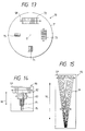
- the plurality of types of linear scales are attained by providing a scale pattern having a continuously changing scale lencth so that a pitch of the grating gradually changes, on a scale base plate.
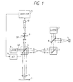
- Another laser light source 8 for emitting a laser beam LB to the scanner 5 is provided.
- the laser beam LB reflected by the scanner 5 is focused on a screen mask 9 as a light spot which vibrates in synchronism with the light spot on the sample 1.
- the laser beam LB transmitted through the screen mask 9 is detected by a detector 10, and a detection signal of the detector 10 is applied to a control circuit 11 for processing.
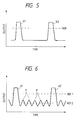
- the output signal of the detector 10 is binarized by a slice level Ref and it is supplied to the interval counter 15 which counts the time interval between the two peaks b1 and b2. Since the drive frequency of the vibration mirror 5 is constant, the time interval is reduced as the amplitude of the vibration mirror 5 is increased, and is increased when the amplitude of the mirror is decreased.
- the controller 16 compares the output interval of the detection signal counted by the interval counter 15 with the exact reference time from the reference time generator 17 and supplies an amplification factor feedback signal to the amplifier 13, which controls the amplification factor in accordance with the feedback signal from the controller 16. As a result, the amplitude of the mirror 5 is controlled such that the time interval of the two peaks b1 and b2 of the output signal is always kept constant.
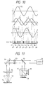
- the output signal of the detector 10 produced through the screen mask 19 is shown in Fig. 6.
- Two peaks d1 and d2 are generated to correspond to the points C1 and C2, and a number of peaks e are generated between the two peaks to correspond to the pitch of the linear scale.
- the two peaks are binarized by a slice level Ref 1 and it is used for the amplitude control of the vibration mirror.
- the peaks e are binarized by a slice level Ref 2 and it is used as a video clock signal to be used for the A/D conversion of the image information.
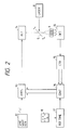
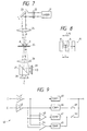
- a processing circuit 40 generates a clock signal based on the output signals of the photo-sensors 28 and 29, and a sum signal and a difference signal thereof.
- the processing circuit 40 comprises I/V conversion amplifiers 41 and 42 for receiving electrical output signals C and D from the two photo-sensors 28 and 29, a summing amplifier 43 for summing the outputs of the I/V conversion amplifiers 41 and 42 to produce a sum signal, a differential amplifier 44 for differentiating the output to produce a differential signal, comparators 45 - 48 for forming clock signals from the outputs of the I/V conversion amplifiers 41 and 42 and the outputs of the amplifiers 43 and 44, and clock varying switches 49 and 50.
Landscapes
- Engineering & Computer Science (AREA)
- Multimedia (AREA)
- Signal Processing (AREA)
- Physics & Mathematics (AREA)
- Optics & Photonics (AREA)
- Mechanical Optical Scanning Systems (AREA)
Claims (15)
- Générateur de signaux d'horloge vidéo pour la production d'un signal d'horloge vidéo au moyen d'un mouvement de balayage d'un faisceau laser le long d'une échelle (72,73,74,75,82,83,84,85,91) équipée de repères, le générateur comprenant un scanner optique (5) pour réaliser un balayage du faisceau de lumière, et des moyens (67) pour produire le signal d'horloge vidéo sur la base de l'information optique provenant de l'échelle,
caractérisé en ce que ledit générateur comprend :une pluralité d'échelles pouvant être sélectionnées (72,73,74,75;82,83,84,85;91) possédant des longueurs différentes, etdes moyens (16, 65) pour commander l'amplitude du scanner en fonction de la longueur de l'échelle sélectionnée. - Générateur de signaux d'horloge vidéo selon la revendication 1, dans lequel lesdites échelles (72,73,74,75;82,83,84,85;91) possèdent chacune des repères sous la forme d'une pluralité de réseaux de diffraction disposés longitudinalement.
- Générateur de signaux d'horloge vidéo selon la revendication 1 ou 2, comprenant en outre des moyens (61) pour positionner sélectivement les échelles sur un axe optique.
- Générateur de signaux d'horloge vidéo selon la revendication 1, 2 ou 3, comprenant en outre des moyens (8) de délivrance de faisceau pour délivrer un faisceau pour former un spot de lumière sur l'échelle sélectionnée.
- Générateur de signaux d'horloge vidéo selon la revendication 4, dans lequel le scanner optique (5) est un miroir de scanner vibrant pour faire vibrer le spot de lumière sur l'échelle (72,73,74,75;82,83,84,85;91) dans la direction du réseau des repères.
- Générateur de signaux d'horloge vidéo selon l'une quelconque des revendications 1 à 5, dans lequel les nombres de repères des échelles (72,73,74,75;82,83,84, 85;91) sont égaux et les pas des repères sont différents d'une échelle à l'autre.
- Générateur de signaux d'horloge vidéo selon l'une quelconque des revendications 1 à 6, dans lequel lesdites échelles (72,73,74,75;82,83,84,85;91) incluent une pluralité de réseaux d'échelles ayant différentes longueurs et disposés sur une plaque d'échelle (70;80;90).
- Générateur de signaux d'horloge vidéo selon l'une quelconque des revendications 1 à 6, dans lequel ladite pluralité d'échelles (91) sont pourvues de repères se présentant sous la forme d'un réseau possédant un pas qui est continûment variable perpendiculairement à la direction de balayage.
- Générateur de signaux d'horloge vidéo selon l'une quelconque des revendications 1 à 8, dans lequel lesdits moyens de commande d'amplitude comprennent des moyens (64) pour mémoriser préalablement des données d'amplitude pour chaque échelle, et des moyens (65) pour commander le scanner optique (5) en fonction des données d'amplitude de l'échelle sélectionnée lues à partir des moyens de mémorisation préalable.
- Générateur de signaux d'horloge vidéo selon l'une quelconque des revendications 1 à 9, comprenant en outre des moyens (62, 63) pour déterminer automatiquement laquelle de ladite pluralité d'échelles est explorée par balayage, lesdits moyens de commande d'amplitude commandant l'amplitude du scanner optique (5) en réponse à cette détermination.
- Générateur de signaux d'horloge vidéo selon l'une quelconque des revendications 1 à 10, comprenant en outre :un détecteur (10) pour produire un signal de sortie représentant une information optique provenant de l'échelle sélectionnée ;un compteur (15) pour compter un intervalle de temps nécessaire pour un spot de lumière produit par le faisceau de lumière pour croiser les extrémités opposées de l'échelle sélectionnée sur la base du signal de sortie du détecteur, et dans lequel ledit scanner optique (5) réfléchit le faisceau de lumière pour déplacer le spot de lumière au-delà des extrémités opposées de l'échelle linéaire ; etlesdits moyens de commande d'amplitude commandent l'amplitude du scanner optique (5) en fonction de l'intervalle de temps compté par le compteur.
- Générateur de signaux d'horloge vidéo selon la revendication 11, dans lequel lesdits moyens de commande comprennent des moyens (17) pour régler un temps de référence, et commandent l'amplitude du scanner optique (5) de telle sorte que le temps compté par le compteur (15) est lié, selon une relation prédéterminée, au temps de référence.
- Générateur de signaux d'horloge vidéo selon la revendication 12, dans lequel lesdits moyens de commande comprennent des moyens (12) pour produire un signal en onde sinusoïdale, un amplificateur (13) possédant un facteur d'amplification variable et servant à amplifier le signal en onde sinusoïdale et un actionneur (14) pour faire vibrer le scanner optique (5) en fonction du signal d'onde sinusoïdale amplifié.
- Générateur de signaux d'horloge vidéo selon l'une quelconque des revendications 1 à 13, dans lequel lesdites échelles sont des échelles linéaires.
- Dispositif d'entrée d'images de balayage optique comprenant un générateur de signaux d'horloge vidéo selon l'une quelconque des revendications 1 à 14 et comprenant en outre :des moyens pour produire un signal d'image synchronisé avec le scanner optique ; etdes moyens pour former une image à partir du signal d'image et du signal d'horloge vidéo.
Priority Applications (1)
| Application Number | Priority Date | Filing Date | Title |
|---|---|---|---|
| EP96113812A EP0748098A3 (fr) | 1991-11-07 | 1992-11-02 | Générateur d'horloge vidéo pour dispositif de balayage optique d'image |
Applications Claiming Priority (6)
| Application Number | Priority Date | Filing Date | Title |
|---|---|---|---|
| JP3291723A JPH05127109A (ja) | 1991-11-07 | 1991-11-07 | 振動光学要素の振幅制御装置および制御方法 |
| JP03291724A JP3111551B2 (ja) | 1991-11-07 | 1991-11-07 | ビデオクロック信号発生装置 |
| JP291723/91 | 1991-11-07 | ||
| JP291724/91 | 1991-11-07 | ||
| JP295944/91 | 1991-11-12 | ||
| JP3295944A JPH05136954A (ja) | 1991-11-12 | 1991-11-12 | ビデオクロツク信号発生装置 |
Related Child Applications (1)
| Application Number | Title | Priority Date | Filing Date |
|---|---|---|---|
| EP96113812A Division EP0748098A3 (fr) | 1991-11-07 | 1992-11-02 | Générateur d'horloge vidéo pour dispositif de balayage optique d'image |
Publications (3)
| Publication Number | Publication Date |
|---|---|
| EP0541321A2 EP0541321A2 (fr) | 1993-05-12 |
| EP0541321A3 EP0541321A3 (en) | 1993-08-25 |
| EP0541321B1 true EP0541321B1 (fr) | 1999-03-10 |
Family
ID=27337686
Family Applications (2)
| Application Number | Title | Priority Date | Filing Date |
|---|---|---|---|
| EP92310037A Expired - Lifetime EP0541321B1 (fr) | 1991-11-07 | 1992-11-02 | Générateur d'horloge vidéo pour dispositif de balayage optique d'image |
| EP96113812A Withdrawn EP0748098A3 (fr) | 1991-11-07 | 1992-11-02 | Générateur d'horloge vidéo pour dispositif de balayage optique d'image |
Family Applications After (1)
| Application Number | Title | Priority Date | Filing Date |
|---|---|---|---|
| EP96113812A Withdrawn EP0748098A3 (fr) | 1991-11-07 | 1992-11-02 | Générateur d'horloge vidéo pour dispositif de balayage optique d'image |
Country Status (2)
| Country | Link |
|---|---|
| EP (2) | EP0541321B1 (fr) |
| DE (1) | DE69228583T2 (fr) |
Families Citing this family (1)
| Publication number | Priority date | Publication date | Assignee | Title |
|---|---|---|---|---|
| CN115929843B (zh) * | 2022-12-12 | 2025-06-03 | 中国船舶集团有限公司第七〇四研究所 | 一种船舶并联式混合动力系统振动抑制方法 |
Family Cites Families (10)
| Publication number | Priority date | Publication date | Assignee | Title |
|---|---|---|---|---|
| US4044248A (en) * | 1972-05-03 | 1977-08-23 | Eastman Kodak Company | Method and apparatus for linearizing a mirror galvanometer |
| JPS54160117A (en) * | 1978-06-09 | 1979-12-18 | Toshiba Corp | Optical scanner |
| JPS56104571A (en) * | 1980-01-24 | 1981-08-20 | Canon Inc | Picture output device |
| US4661699A (en) * | 1983-03-28 | 1987-04-28 | T. R. Whitney Corporation | Scanning beam control system and method with bi-directional reference scale |
| US4600951A (en) * | 1983-12-20 | 1986-07-15 | At&T Technologies, Inc. | Scanning sample, signal generation, data digitizing and retiming system |
| EP0147835B1 (fr) * | 1983-12-28 | 1991-02-27 | Fuji Photo Film Co., Ltd. | Appareil d'analyse à faisceau lumineux |
| US4584612A (en) * | 1984-02-21 | 1986-04-22 | Dainippon Screen Seizo Kabushiki Kaisha | Picture recording method |
| US4761660A (en) * | 1986-12-15 | 1988-08-02 | Minnesota Mining And Manufacturing Company | Laser scanning apparatus using a fan style grating plate |
| US4962431A (en) * | 1987-05-08 | 1990-10-09 | Ricoh Company, Ltd. | Synchronizing signal generating system for laser scanner |
| EP0357190B1 (fr) * | 1988-08-30 | 1995-04-05 | Kabushiki Kaisha TEC | Balayeur optique |
-
1992
- 1992-11-02 EP EP92310037A patent/EP0541321B1/fr not_active Expired - Lifetime
- 1992-11-02 DE DE69228583T patent/DE69228583T2/de not_active Expired - Lifetime
- 1992-11-02 EP EP96113812A patent/EP0748098A3/fr not_active Withdrawn
Also Published As
| Publication number | Publication date |
|---|---|
| EP0541321A3 (en) | 1993-08-25 |
| EP0541321A2 (fr) | 1993-05-12 |
| DE69228583T2 (de) | 1999-07-01 |
| DE69228583D1 (de) | 1999-04-15 |
| EP0748098A3 (fr) | 1997-03-12 |
| EP0748098A2 (fr) | 1996-12-11 |
Similar Documents
| Publication | Publication Date | Title |
|---|---|---|
| US5668644A (en) | Video clock signal generator in an optical scanner in which a mask including a linear scale provides timing for controlling the amplitude of a vibrating mirror | |
| US5844591A (en) | Multibeam laser recording apparatus | |
| KR100499879B1 (ko) | 광빔편향장치, 그것을 이용한 화상형성장치 및 그구동방법 | |
| US4352981A (en) | Photoelectric focus and tracking apparatus | |
| AU597971B2 (en) | Scanning apparatus | |
| US5185676A (en) | Beam scanning apparatus and apparatus for writing image information | |
| JPH04155304A (ja) | 集光位置検出装置 | |
| JPS60120316A (ja) | 光ビ−ム走査装置 | |
| US4931637A (en) | Scanner utilizing a particular light guide | |
| US5166820A (en) | Light beam scanning apparatus | |
| US5121449A (en) | Information detecting system of scanning type | |
| JP3667816B2 (ja) | 円筒内面走査型画像記録装置 | |
| JP4036911B2 (ja) | マルチビーム走査装置 | |
| US5233188A (en) | Laser beam scanning apparatus for scanning a laser beam obtained by composing a plurality of beams | |
| US20020088924A1 (en) | Digital laser image recorder | |
| JPH05128548A (ja) | 光学式走査装置 | |
| EP0541321B1 (fr) | Générateur d'horloge vidéo pour dispositif de balayage optique d'image | |
| EP0773461A2 (fr) | Méthode et appareil pour balayage à faisceaux multiples | |
| JPH06229753A (ja) | スキャナシステム | |
| JPH09325288A (ja) | マルチビ−ム走査装置 | |
| JPS58179815A (ja) | 光走査装置 | |
| JP3299186B2 (ja) | 走査位置検出機能を有する光走査装置 | |
| JPH0611741A (ja) | 光装置 | |
| JPH0485510A (ja) | レーザ光走査装置 | |
| JP3111551B2 (ja) | ビデオクロック信号発生装置 |
Legal Events
| Date | Code | Title | Description |
|---|---|---|---|
| PUAI | Public reference made under article 153(3) epc to a published international application that has entered the european phase |
Free format text: ORIGINAL CODE: 0009012 |
|
| AK | Designated contracting states |
Kind code of ref document: A2 Designated state(s): DE GB |
|
| RIN1 | Information on inventor provided before grant (corrected) |
Inventor name: KUMAGAI, SATORU Inventor name: ICHIHARA, YUTAKA Inventor name: OKUGAWA, HISASHI Inventor name: NISHIDA, HIROSHI Inventor name: KUROIWA, YOSHINORI |
|
| PUAL | Search report despatched |
Free format text: ORIGINAL CODE: 0009013 |
|
| AK | Designated contracting states |
Kind code of ref document: A3 Designated state(s): DE GB |
|
| 17P | Request for examination filed |
Effective date: 19940221 |
|
| 17Q | First examination report despatched |
Effective date: 19960212 |
|
| GRAG | Despatch of communication of intention to grant |
Free format text: ORIGINAL CODE: EPIDOS AGRA |
|
| GRAG | Despatch of communication of intention to grant |
Free format text: ORIGINAL CODE: EPIDOS AGRA |
|
| GRAG | Despatch of communication of intention to grant |
Free format text: ORIGINAL CODE: EPIDOS AGRA |
|
| GRAH | Despatch of communication of intention to grant a patent |
Free format text: ORIGINAL CODE: EPIDOS IGRA |
|
| GRAH | Despatch of communication of intention to grant a patent |
Free format text: ORIGINAL CODE: EPIDOS IGRA |
|
| GRAA | (expected) grant |
Free format text: ORIGINAL CODE: 0009210 |
|
| AK | Designated contracting states |
Kind code of ref document: B1 Designated state(s): DE GB |
|
| DX | Miscellaneous (deleted) | ||
| REF | Corresponds to: |
Ref document number: 69228583 Country of ref document: DE Date of ref document: 19990415 |
|
| PLBE | No opposition filed within time limit |
Free format text: ORIGINAL CODE: 0009261 |
|
| 26N | No opposition filed | ||
| REG | Reference to a national code |
Ref country code: GB Ref legal event code: IF02 |
|
| PGFP | Annual fee paid to national office [announced via postgrant information from national office to epo] |
Ref country code: GB Payment date: 20061101 Year of fee payment: 15 |
|
| GBPC | Gb: european patent ceased through non-payment of renewal fee |
Effective date: 20071102 |
|
| PG25 | Lapsed in a contracting state [announced via postgrant information from national office to epo] |
Ref country code: GB Free format text: LAPSE BECAUSE OF NON-PAYMENT OF DUE FEES Effective date: 20071102 |
|
| PGFP | Annual fee paid to national office [announced via postgrant information from national office to epo] |
Ref country code: DE Payment date: 20101027 Year of fee payment: 19 |
|
| REG | Reference to a national code |
Ref country code: DE Ref legal event code: R071 Ref document number: 69228583 Country of ref document: DE |
|
| REG | Reference to a national code |
Ref country code: DE Ref legal event code: R071 Ref document number: 69228583 Country of ref document: DE |