EP0541368B1 - Radialluftreifen für Zweiradfahrzeuge - Google Patents
Radialluftreifen für Zweiradfahrzeuge Download PDFInfo
- Publication number
- EP0541368B1 EP0541368B1 EP92310126A EP92310126A EP0541368B1 EP 0541368 B1 EP0541368 B1 EP 0541368B1 EP 92310126 A EP92310126 A EP 92310126A EP 92310126 A EP92310126 A EP 92310126A EP 0541368 B1 EP0541368 B1 EP 0541368B1
- Authority
- EP
- European Patent Office
- Prior art keywords
- belt
- cords
- tire
- ply
- belt ply
- Prior art date
- Legal status (The legal status is an assumption and is not a legal conclusion. Google has not performed a legal analysis and makes no representation as to the accuracy of the status listed.)
- Expired - Lifetime
Links
Images



Classifications
-
- B—PERFORMING OPERATIONS; TRANSPORTING
- B60—VEHICLES IN GENERAL
- B60C—VEHICLE TYRES; TYRE INFLATION; TYRE CHANGING; CONNECTING VALVES TO INFLATABLE ELASTIC BODIES IN GENERAL; DEVICES OR ARRANGEMENTS RELATED TO TYRES
- B60C9/00—Reinforcements or ply arrangement of pneumatic tyres
- B60C9/18—Structure or arrangement of belts or breakers, crown-reinforcing or cushioning layers
- B60C9/20—Structure or arrangement of belts or breakers, crown-reinforcing or cushioning layers built-up from rubberised plies each having all cords arranged substantially parallel
- B60C9/22—Structure or arrangement of belts or breakers, crown-reinforcing or cushioning layers built-up from rubberised plies each having all cords arranged substantially parallel the plies being arranged with all cords disposed along the circumference of the tyre
- B60C9/2204—Structure or arrangement of belts or breakers, crown-reinforcing or cushioning layers built-up from rubberised plies each having all cords arranged substantially parallel the plies being arranged with all cords disposed along the circumference of the tyre obtained by circumferentially narrow strip winding
-
- B—PERFORMING OPERATIONS; TRANSPORTING
- B60—VEHICLES IN GENERAL
- B60C—VEHICLE TYRES; TYRE INFLATION; TYRE CHANGING; CONNECTING VALVES TO INFLATABLE ELASTIC BODIES IN GENERAL; DEVICES OR ARRANGEMENTS RELATED TO TYRES
- B60C9/00—Reinforcements or ply arrangement of pneumatic tyres
- B60C9/18—Structure or arrangement of belts or breakers, crown-reinforcing or cushioning layers
- B60C9/20—Structure or arrangement of belts or breakers, crown-reinforcing or cushioning layers built-up from rubberised plies each having all cords arranged substantially parallel
- B60C9/2003—Structure or arrangement of belts or breakers, crown-reinforcing or cushioning layers built-up from rubberised plies each having all cords arranged substantially parallel characterised by the materials of the belt cords
- B60C9/2009—Structure or arrangement of belts or breakers, crown-reinforcing or cushioning layers built-up from rubberised plies each having all cords arranged substantially parallel characterised by the materials of the belt cords comprising plies of different materials
-
- Y—GENERAL TAGGING OF NEW TECHNOLOGICAL DEVELOPMENTS; GENERAL TAGGING OF CROSS-SECTIONAL TECHNOLOGIES SPANNING OVER SEVERAL SECTIONS OF THE IPC; TECHNICAL SUBJECTS COVERED BY FORMER USPC CROSS-REFERENCE ART COLLECTIONS [XRACs] AND DIGESTS
- Y10—TECHNICAL SUBJECTS COVERED BY FORMER USPC
- Y10T—TECHNICAL SUBJECTS COVERED BY FORMER US CLASSIFICATION
- Y10T152/00—Resilient tires and wheels
- Y10T152/10—Tires, resilient
- Y10T152/10495—Pneumatic tire or inner tube
- Y10T152/10765—Characterized by belt or breaker structure
-
- Y—GENERAL TAGGING OF NEW TECHNOLOGICAL DEVELOPMENTS; GENERAL TAGGING OF CROSS-SECTIONAL TECHNOLOGIES SPANNING OVER SEVERAL SECTIONS OF THE IPC; TECHNICAL SUBJECTS COVERED BY FORMER USPC CROSS-REFERENCE ART COLLECTIONS [XRACs] AND DIGESTS
- Y10—TECHNICAL SUBJECTS COVERED BY FORMER USPC
- Y10T—TECHNICAL SUBJECTS COVERED BY FORMER US CLASSIFICATION
- Y10T152/00—Resilient tires and wheels
- Y10T152/10—Tires, resilient
- Y10T152/10495—Pneumatic tire or inner tube
- Y10T152/10765—Characterized by belt or breaker structure
- Y10T152/10783—Reinforcing plies made up from wound narrow ribbons
Definitions
- the present invention relates to pneumatic radial tires for two-wheeled vehicles, and particularly to a belt structure therefor.
- the invention is specifically aimed at increasing tread-gripping forces when the vehicle turns, reducing the number of working steps in the formation of the belt, and decreasing the weight of the tire.
- the tire of this type has low bending rigidity in a widthwise sectional plane. Accordingly, particularly when a vehicle is turned under application of a camber angle to the tire, rigidity is insufficient in a shoulder portion of the tread, and therefore high tread-gripping forces cannot be obtained. This defect is more serious with increased turning speed.
- the proposed technique needs an additional step to bond the innermost cord ply on forming the tire, which unfavorably increases the number of working steps and the weight of the tire.
- the present invention has been accomplished through investigations to solve the above-mentioned problems possessed by the prior art, and the invention is aimed at the provision of radial tires for two-wheeled vehicles, which can sufficiently reduce the number of the working steps for the preparation of the belt, can effectively prevent increase in weight of the tire, have excellent high speed stability, and particularly improve tread-gripping forces on turning of the vehicle.
- the present invention provides a pneumatic radial tire for a two-wheeled vehicle, comprising a carcass constituted by at least one carcass ply composed of cords extending at an angle of 75 to 90° with respect to an equatorial plane of the tire, and a belt constituted by at least two belt plies, each of said belt plies being arranged radially outwardly and adjacent on an outer peripheral side of a crown portion of said carcass and composed of cords extending substantially in the circumferential direction of the tire, wherein a number of the cords per unit width of an outermost belt ply is in a range of 30% to 80%, preferably in a range of 40% to 60%, of that of a belt ply adjacent radially inwardly of said outermost belt ply as considered on average over the entire width of the belt.
- the tire can exhibit excellent high speed durability and high speed stability under excellent ground-contacting property as described above in connection with the prior art. Further, since the tire is provided with at least two belt plies, bending strength is advantageously increased within a widthwise sectional plane of the tire, particularly to effectively enhance the tread-gripping forces when the vehicle turns.
- each belt ply can be formed in this tire by spirally winding one cord or a unit of plural cords around the crown portion of the carcass with use of an automatic winding machine, the belt ply, and accordingly the belt, can be rapidly formed by a smaller number of working steps. Furthermore, the weight of the tire can be effectively reduced by setting the number of the cords per unit width of the outermost belt ply in the belt at 30% to 80% of that of the belt ply adjacent radially inwardly to the outermost belt ply as considered over the entire width of the belt.
- the reason why the number of the cords per unit width of the outermost belt ply in the belt is set at 30% to 80% of that of the belt ply adjacent radially inwardly to the outermost belt ply as considered over the entire width of the belt is that if the above number of the cords per unit width of the outermost belt ply is less than 30%, bending rigidity in the widthwise sectional plane of the tire cannot be fully enhanced, whereas if this number of cords per unit width is more than 80%, rigidity becomes too great, or the weight cannot be reduced so much.
- Fig. 1 is a sectional view of one embodiment of the present invention as taken in the tire-width direction.
- a carcass 2 extends between a pair of two bead cores 1.
- the carcass 2 consists of a single carcass ply composed of cords extending at an angle of 75° to 90° with respect to the circumferential direction of the tire, and a belt 4 is arranged on a radially outer side of a crown portion of the carcass 2.
- This belt 4 has a width substantially equal to the entire width of the tread 3.
- the belt 4 is composed of two belt plies 4a and 4b adjacent radially to each other on outer and inner sides.
- Each of the belt plies 4a and 4b is formed by spirally winding a single belt ply cord or a plurality of belt ply cords radially outwardly around the carcass 2, so that the cords in each of the belt plies may extend substantially in the circumferential direction of the tire.
- the number of the cords per unit width of the radially outwardly located belt ply 4b of the two inner and outer belt plies 4a and 4b is set in a range of 30% to 80%, preferably 40% to 60%, of that of the belt ply 4a located on the radially inner side of the belt ply 4b, as considered over the entire width W of the belt 4.
- the arrayed state of the cords in the belt ply 4b with respect to the cords in the belt ply 4a may be as shown in Fig. 2(a) or Fig. 2(b). That is, in Fig.
- the cords in the belt ply 4b are arrayed in a uniformly coarsely wound state to meet the above ratio relationship with respect to the number of the cords per unit width, whereas in Fig. 2(b) the cords in the belt ply 4b are so arranged as to have relatively coarsely wound portions and relatively closely wound portions at different locations of the belt in the width direction.
- the cords constituting the belt plies 4a and 4b are preferably steel cords or organic fiber cords made of for example aromatic polyamide, polyvinyl alcohol, nylon, polyester, and high modulus polyester.
- a belt ply may be formed by first forming a band-like strip (ribbon-shaped member) through coating a plurality of parallel cords with rubber and winding the thus formed strip around the carcass.
- productivity can be greatly improved as compared with the case where a single cord is spirally wound.
- Fig. 3 is a sectional view of another embodiment of the present invention as taken along a width direction of the tire.
- cords of a belt ply 4b located on a radially outer side of a belt 4 are arrayed on axially opposite side portions of the belt 4 each over a width equal to about 1/4 of the width W of the belt such that the number of the cords of the belt ply 4b per unit width may be substantially equal to that of a radially inner belt ply 4a, whereas the cords of the radially outer belt ply 4b are completely omitted in a central portion of the belt 4 corresponding to about 1/2 of the width of the belt.
- the number of the cords of the radially outer belt ply 4b is set in a range of 30% to 80% of that of the radially inner belt ply 4a as considered on average over the entire width of the belt.
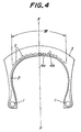
- Fig. 4 is a sectional view of a still another embodiment of the present invention as taken along a tire-width direction.
- This embodiment is characterized in that radially inner and outer belt plies 4a and 4b are formed by first preparing a rubberized tape or a ribbon-shaped member S in which a plurality of cords are arrayed in parallel to each other and spirally winding the rubberized tape or the ribbon-shaped member around a carcass.
- the radially outer belt ply 4b is laterally symmetrically arranged with respect to the tire equatorial plane, and restricted in a location corresponding to a central portion of the tread 3. Only the radially inner belt ply 4a is arranged in locations corresponding to opposite side portions of the tread.
- the belt plies 4a and 4b are formed by spirally winding the tape or ribbon-shaped member such that the tape or ribbon-shaped member may be substantially butted between adjacent turns thereof.
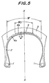
- Fig. 5 is a sectional view of a still further embodiment of the present invention. This embodiment differs from that of Fig. 4 in that an inner belt ply 4a and an outer belt ply 4b are formed by spirally wrapping a tape S while partially overlapping the tape in a location corresponding to a central portion W1 of the tread.
- An overlapped width w of adjacent turns of the tape is preferably 20% to 70% of the width of the tape S.
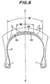
- Fig. 6 is a radial sectional view of a still further embodiment of the present invention.
- This embodiment is characterized in that an inner belt ply 4a is formed by spirally wrapping a tape side by side as in the case of the inner belt ply 4a in Fig. 4, and an outer belt ply 4b is formed by partially overlapping the tape in a central location W1. Consequently, a third belt ply is formed between the inner and outer belt plies 4a and 4b in this location W1.
- Fig. 7 is a radial sectional view of a still further embodiment of the present invention.
- This embodiment is characterized in that a belt is formed by spirally and circumferentially wrapping a tape from a starting point Ps inside a belt width W side by side toward an end point D, further continuing to wrap the tape around the continuously formed ply 4a toward an opposite end point E when the tape reaches the point D, and finally wrapping the tape toward the end point D up to a terminal point Pe.
- the outer belt ply 4b is located in a central portion W I between the points Ps and Pe, and a third belt ply 4c is formed over the entire belt width W on the radially outer side of the inner belt ply 4a.
- Tire 1 was a tire as shown in Fig. 1 having a tire size of 170/60R17 in which a carcass was constituted by a single carcass ply composed of nylon cords (1500d/2) extending at 90° with respect to the tire circumferential direction, a belt was constituted by two belt plies composed of aromatic polyamide cords (1500d/2), and the number of the cords of the radially outer belt ply per unit width was set at 0.5 of that of the radially inner belt ply.
- Invention Tire 2 was a tire as shown in Fig. 3 having a tire size of 170/60R17 in which a radially outer belt ply was arranged on axially opposite side portions of the belt each over a width equal to 1/4 of the width of the belt.
- Comparison Tire 1 had the same construction as that of Invention Tire 1 except that the radially outer ply was omitted.
- Comparison Tire had the same construction as that of Invention Tire 1 except that the number of the cords per unit width was made equal between the radially inner and outer belt plies.
- Each of the above tires was fitted to a rear wheel of a sport type 750cc two-wheeled vehicle, and run on a test course. Various performances were evaluated by feeling at that time.
- Table 1 Straight running stability Tread-gripping forces Tread rigidity Riding comfortability Invention Tire 1 7 8 7 7 Invention Tire 2 7 8.5 7 7 Comparison Tire 1 7 7 6 7 Comparison Tire 2 7 7 7.5 6
- Invention Tire 1 can effectively enhance the gripping forces due to increase in the rigidity of the tread without deteriorating the riding comfortability, and Invention Tire 2 can enhance the gripping forces on full banking without deteriorating the riding comfortability.
- the belt can be easily formed, the weight of the tire can be effectively reduced, the rigidity of the tread can be attained as desired, and the tread-gripping forces on cornering can be effectively enhanced.
Landscapes
- Engineering & Computer Science (AREA)
- Mechanical Engineering (AREA)
- Tires In General (AREA)
- Yarns And Mechanical Finishing Of Yarns Or Ropes (AREA)
Claims (12)
- Radialluftreifen für ein Zweiradfahrzeug, der folgende Komponenten aufweist: eine Karkasse (2), die durch wenigstens eine Karkassenlage gebildet wird, die aus Korden zusammengesetzt ist, die in einem Winkel von 75° bis 90° im Verhältnis zu einer Äquatorialebene (X-X) des Reifens verlaufen, und einen Gürtel (4), der durch wenigstens Zwei Gürtellagen (4a, 4b) gebildet wird, wobei jede der Gürtellagen in Radialrichtung nach außen und im Anschluß an eine äußere Umfangsseite eines Zenitabschnitts der Karkasse angeordnet ist und aus Korden zusammengesetzt ist, die im wesentlichen in der Umfangsrichtung des Reifens verlaufen, dadurch gekennzeichnet, daß die Zahl der Korde je Breiteneinheit bei einer äußersten Gürtellage (4b) in einem Bereich von 30% bis 80% derjenigen einer Gürtellage (4a) liegt, die in der Radialrichtung nach innen an die äußerste Gürtellage angrenzt, bezogen im Durchschnitt auf die gesamte Breite des Gürtels.
- Reifen nach Anspruch 1, dadurch gekennzeichnet, daß die Zahl der Korde je Breiteneinheit bei der äußersten Gürtellage (4b) im Bereich von 40% bis 60% derjenigen der Gürtellage (4a) liegt, die in der Radialrichtung nach innen an die äußerste Gürtellage angrenzt, bezogen im Durchschnitt auf die gesamte Breite des Gürtels.
- Reifen nach Anspruch 1 oder 2, dadurch gekennzeichnet, daß die Korde in der in Radialrichtung äußersten Gürtellage (4b) in einem gleichmäßig weit gewundenem Zustand angeordnet sind.
- Reifen nach Anspruch 1 oder 2, dadurch gekennzeichnet, daß die Korde in der in Radialrichtung äußeren Gürtellage (4b) so angeordnet sind, daß sie relativ weit gewundene Abschnitte und relativ eng gewundene Abschnitte haben.
- Reifen nach Anspruch 1 oder 2, dadurch gekennzeichnet, daß die Korde der äußersten Gürtellage (4b) in einer gespaltenen Weise auf den in Axialrichtung gegenüberliegenden Seitenabschnitten des Gürtels (4) angeordnet sind.
- Reifen nach Anspruch 5, dadurch gekennzeichnet, daß sich die Korde der äußersten Gürtellage (4b) auf jedem der in Axialrichtung gegenüberliegenden Seitenabschnitte des Gürtels (4) über eine Breite erstrecken, die gleich etwa 1/4 der Breite (W) des Gürtels ist, so daß die Zahl der Korde der Gürtellage (4b) je Breiteneinheit im wesentlichen gleich derjenigen der in Radialrichtung inneren Gürtellage (4a) ist, während die Korde der in Radialrichtung äußeren Gürtellage (4b) in einem Mittelabschnitt des Gürtels, der etwa 1/2 der Breite des Gürtels entspricht, entfallen.
- Reifen nach einem der Ansprüche 1 bis 6, dadurch gekennzeichnet, daß die Korde in den Gürtellagen (4a, 4b) ausgewählt werden aus Stahlkorden und Korden aus aromatischem Polyamid, Korden aus Polyvinylalkohol, Nylonkorden, Polyesterkorden und Korden aus Polyester mit hohem Spannungswert.
- Reifen nach einem der Ansprüche 1 bis 7, dadurch gekennzeichnet, daß die in Radialrichtung innere und äußere Gürtellage (4a, 4b) dadurch gebildet werden, daß zuerst ein gummiertes Band oder ein bandförmiges Element (S) hergestellt wird, in dem eine Vielzahl von Korden parallel zueinander angeordnet ist, und dann das gummierte Band oder das bandförmige Element spiralförmig um eine Karkasse gewickelt wird.
- Reifen nach einem der Ansprüche 1 bis 8, dadurch gekennzeichnet, daß die in Radialrichtung innere Gürtellage (4a) durch das spiralförmige Umwickeln eines Bandes (S), Seite an Seite, gebildet wird, und die in Radialrichtung äußere Gürtellage (4b) durch teilweises Überlappen des Bandes in einer mittleren Position gebildet wird.
- Reifen nach einem der Ansprüche 1 bis 8, dadurch gekennzeichnet, daß die innere Gürtellage (4a) durch das spriralförmige Umwickeln eines Bandes (S), Seite an Seite, gebildet wird, und eine äußere Gürtellage (4b) durch das teilweise Überlappen des Bandes in einer mittleren Position (W₁) gebildet wird, so daß zwischen der inneren und der äußeren Gürtellage (4a, 4b) in der mittleren Position (W₁) eine dritte Gürtellage (4c) gebildet wird.
- Reifen nach einem der Ansprüche 1 bis 8, dadurch gekennzeichnet, daß der Gürtel hergestellt wird durch spiralförmiges und über den Umfang führendes Umwickeln eines Bandes (S) von einem Ausgangspunkt (Ps) innerhalb der Breite (W) des Gürtels, Seite an Seite zu einem Endpunkt (D), weiteres Wickeln des Bandes um die so gebildete durchgängige Lage (4a) zu einem gegenüberliegenden Endpunkt (E), wenn das Band den Endpunkt (D) erreicht hat, und abschließendes Wickeln des Bandes in Richtung auf den Endpunkt (D), bis zu einem Abschlußpunkt (Pe).
- Reifen nach einem der Ansprüche 8 bis 11, dadurch gekennzeichnet, daß das Band ein gummiertes Band oder ein bandförmiges Element ist, in dem eine Vielzahl von Korden parallel zueinander angeordnet ist.
Applications Claiming Priority (2)
| Application Number | Priority Date | Filing Date | Title |
|---|---|---|---|
| JP03289966A JP3142920B2 (ja) | 1991-11-06 | 1991-11-06 | 二輪車用空気入りラジアルタイヤ |
| JP289966/91 | 1991-11-06 |
Publications (2)
| Publication Number | Publication Date |
|---|---|
| EP0541368A1 EP0541368A1 (de) | 1993-05-12 |
| EP0541368B1 true EP0541368B1 (de) | 1996-05-15 |
Family
ID=17750034
Family Applications (1)
| Application Number | Title | Priority Date | Filing Date |
|---|---|---|---|
| EP92310126A Expired - Lifetime EP0541368B1 (de) | 1991-11-06 | 1992-11-05 | Radialluftreifen für Zweiradfahrzeuge |
Country Status (4)
| Country | Link |
|---|---|
| US (1) | US5355926A (de) |
| EP (1) | EP0541368B1 (de) |
| JP (1) | JP3142920B2 (de) |
| DE (1) | DE69210760T2 (de) |
Families Citing this family (8)
| Publication number | Priority date | Publication date | Assignee | Title |
|---|---|---|---|---|
| IT1277400B1 (it) * | 1995-08-01 | 1997-11-10 | Pirelli | Pneumatico ad elevata curvatura trasversale particolarmente per veicolo a due ruote |
| IT1283051B1 (it) | 1996-05-22 | 1998-04-07 | Pirelli | Coppia di pneumatici ad elevata curvatura trasversale,particolarmente per veicoli a due ruote e metodo per il controllo del comportamento |
| IT1283351B1 (it) | 1996-07-29 | 1998-04-17 | Pirelli | Pneumatico ad elevata curvatura trasversale in particolare per ruote anteriori |
| JP4498778B2 (ja) * | 2004-03-12 | 2010-07-07 | 株式会社ブリヂストン | 空気入りタイヤ |
| JP4452135B2 (ja) * | 2004-06-30 | 2010-04-21 | 住友ゴム工業株式会社 | 自動二輪車用空気入りタイヤ |
| JP4818706B2 (ja) * | 2005-12-16 | 2011-11-16 | 株式会社ブリヂストン | 自動二輪車用ラジアルタイヤ |
| FR2966082B1 (fr) * | 2010-10-13 | 2012-10-26 | Michelin Soc Tech | Pneumatique a armature de carcasse radiale pour vehicule de tourisme. |
| JP6785193B2 (ja) * | 2017-06-16 | 2020-11-18 | 株式会社ブリヂストン | タイヤ用樹脂金属複合部材、及びタイヤ |
Family Cites Families (8)
| Publication number | Priority date | Publication date | Assignee | Title |
|---|---|---|---|---|
| SU659419A1 (ru) * | 1974-07-04 | 1979-04-30 | Предприятие П/Я В-8749 | Покрышка пневматической шины |
| US5176770A (en) * | 1984-10-02 | 1993-01-05 | Bridgestone Corporation | Pneumatic belted tires for motorcycles |
| DE3606934A1 (de) * | 1986-03-04 | 1987-09-10 | Continental Gummi Werke Ag | Fahrzeugluftreifen |
| DE3629955C2 (de) * | 1986-09-03 | 1998-11-12 | Continental Ag | Fahrzeugluftreifen |
| EP0524703B1 (de) * | 1987-06-18 | 1996-08-21 | Sumitomo Rubber Industries Limited | Einrichtung zur Herstellung eines Gürtels für Radial-Reifen |
| JPH02128904A (ja) * | 1988-11-09 | 1990-05-17 | Toyo Tire & Rubber Co Ltd | 補助層付きベルトを有するラジアルタイヤ |
| US5186773A (en) * | 1988-11-21 | 1993-02-16 | Sumitomo Rubber Industries, Ltd. | Pneumatic radial tire for passenger cars with specified spacing of tread and band joints |
| US5228933A (en) * | 1989-08-24 | 1993-07-20 | Bridgestone Corporation | High performance pneumatic radial tires |
-
1991
- 1991-11-06 JP JP03289966A patent/JP3142920B2/ja not_active Expired - Fee Related
-
1992
- 1992-10-28 US US07/967,397 patent/US5355926A/en not_active Expired - Lifetime
- 1992-11-05 DE DE69210760T patent/DE69210760T2/de not_active Expired - Fee Related
- 1992-11-05 EP EP92310126A patent/EP0541368B1/de not_active Expired - Lifetime
Also Published As
| Publication number | Publication date |
|---|---|
| JP3142920B2 (ja) | 2001-03-07 |
| EP0541368A1 (de) | 1993-05-12 |
| JPH05124404A (ja) | 1993-05-21 |
| DE69210760D1 (de) | 1996-06-20 |
| DE69210760T2 (de) | 1996-11-07 |
| US5355926A (en) | 1994-10-18 |
Similar Documents
| Publication | Publication Date | Title |
|---|---|---|
| JP2916082B2 (ja) | 空気入りラジアルタイヤ | |
| EP1288023B1 (de) | Geländegängiger Reifen | |
| EP0346106A1 (de) | Luftreifen | |
| US5339878A (en) | Pneumatic tires for motorcycles including a spirally wound belt cord layer | |
| EP3960497B1 (de) | Reifen | |
| EP0635383B1 (de) | Luftreifen | |
| EP0467585B1 (de) | Radialluftreifen für ein Motorrad | |
| US4957151A (en) | Radial tire for passenger cars including folded band layer at the belt edges | |
| EP0622253B1 (de) | Radiale Luftreifen | |
| EP0531136B1 (de) | Hochleistungsradialluftreifen | |
| US4924927A (en) | Low-section pneumatic radial tire | |
| EP1057659B1 (de) | Radialer Reifen für PKW | |
| EP2261060B1 (de) | Motorradreifen | |
| EP0462733B1 (de) | Radial-Luftreifen für hohe Geschwindigkeit | |
| EP0541368B1 (de) | Radialluftreifen für Zweiradfahrzeuge | |
| JP2769040B2 (ja) | 高速走行用空気入りラジアルタイヤ | |
| JPH07112763B2 (ja) | 空気入りラジアルタイヤ | |
| EP0615866B1 (de) | Radiale Luftreifen | |
| US5733395A (en) | Pneumatic tire for two-wheeled vehicle with hard rubber layer outside carcass turn-up | |
| JP3035012B2 (ja) | 空気入りラジアルタイヤ | |
| EP0486274B1 (de) | Radialer Luftreifen | |
| EP0456933B1 (de) | Luftreifen für Motorräder | |
| EP0835768B1 (de) | Luftreifen | |
| EP1488939B1 (de) | Luftreifen | |
| JPH07228106A (ja) | 空気入りタイヤ |
Legal Events
| Date | Code | Title | Description |
|---|---|---|---|
| PUAI | Public reference made under article 153(3) epc to a published international application that has entered the european phase |
Free format text: ORIGINAL CODE: 0009012 |
|
| AK | Designated contracting states |
Kind code of ref document: A1 Designated state(s): DE FR GB IT |
|
| 17P | Request for examination filed |
Effective date: 19931108 |
|
| 17Q | First examination report despatched |
Effective date: 19950125 |
|
| GRAH | Despatch of communication of intention to grant a patent |
Free format text: ORIGINAL CODE: EPIDOS IGRA |
|
| GRAA | (expected) grant |
Free format text: ORIGINAL CODE: 0009210 |
|
| AK | Designated contracting states |
Kind code of ref document: B1 Designated state(s): DE FR GB IT |
|
| ITF | It: translation for a ep patent filed | ||
| REF | Corresponds to: |
Ref document number: 69210760 Country of ref document: DE Date of ref document: 19960620 |
|
| ET | Fr: translation filed | ||
| PLBE | No opposition filed within time limit |
Free format text: ORIGINAL CODE: 0009261 |
|
| 26N | No opposition filed | ||
| REG | Reference to a national code |
Ref country code: GB Ref legal event code: IF02 |
|
| PGFP | Annual fee paid to national office [announced via postgrant information from national office to epo] |
Ref country code: DE Payment date: 20081103 Year of fee payment: 17 |
|
| PGFP | Annual fee paid to national office [announced via postgrant information from national office to epo] |
Ref country code: GB Payment date: 20081105 Year of fee payment: 17 |
|
| PGFP | Annual fee paid to national office [announced via postgrant information from national office to epo] |
Ref country code: IT Payment date: 20091112 Year of fee payment: 18 Ref country code: FR Payment date: 20091123 Year of fee payment: 18 |
|
| GBPC | Gb: european patent ceased through non-payment of renewal fee |
Effective date: 20091105 |
|
| PG25 | Lapsed in a contracting state [announced via postgrant information from national office to epo] |
Ref country code: DE Free format text: LAPSE BECAUSE OF NON-PAYMENT OF DUE FEES Effective date: 20100601 |
|
| PG25 | Lapsed in a contracting state [announced via postgrant information from national office to epo] |
Ref country code: GB Free format text: LAPSE BECAUSE OF NON-PAYMENT OF DUE FEES Effective date: 20091105 |
|
| REG | Reference to a national code |
Ref country code: FR Ref legal event code: ST Effective date: 20110801 |
|
| PG25 | Lapsed in a contracting state [announced via postgrant information from national office to epo] |
Ref country code: FR Free format text: LAPSE BECAUSE OF NON-PAYMENT OF DUE FEES Effective date: 20101130 |
|
| PG25 | Lapsed in a contracting state [announced via postgrant information from national office to epo] |
Ref country code: IT Free format text: LAPSE BECAUSE OF NON-PAYMENT OF DUE FEES Effective date: 20101105 |