EP0541386A1 - Structure de circuit d'interconnexion optique - Google Patents
Structure de circuit d'interconnexion optique Download PDFInfo
- Publication number
- EP0541386A1 EP0541386A1 EP92310178A EP92310178A EP0541386A1 EP 0541386 A1 EP0541386 A1 EP 0541386A1 EP 92310178 A EP92310178 A EP 92310178A EP 92310178 A EP92310178 A EP 92310178A EP 0541386 A1 EP0541386 A1 EP 0541386A1
- Authority
- EP
- European Patent Office
- Prior art keywords
- supporting base
- optical
- semiconductor
- optical element
- substrate
- Prior art date
- Legal status (The legal status is an assumption and is not a legal conclusion. Google has not performed a legal analysis and makes no representation as to the accuracy of the status listed.)
- Withdrawn
Links
Images


Classifications
-
- G—PHYSICS
- G02—OPTICS
- G02B—OPTICAL ELEMENTS, SYSTEMS OR APPARATUS
- G02B6/00—Light guides; Structural details of arrangements comprising light guides and other optical elements, e.g. couplings
- G02B6/24—Coupling light guides
- G02B6/42—Coupling light guides with opto-electronic elements
- G02B6/4201—Packages, e.g. shape, construction, internal or external details
- G02B6/4219—Mechanical fixtures for holding or positioning the elements relative to each other in the couplings; Alignment methods for the elements, e.g. measuring or observing methods especially used therefor
- G02B6/4228—Passive alignment, i.e. without a detection of the degree of coupling or the position of the elements
- G02B6/423—Passive alignment, i.e. without a detection of the degree of coupling or the position of the elements using guiding surfaces for the alignment
-
- G—PHYSICS
- G02—OPTICS
- G02B—OPTICAL ELEMENTS, SYSTEMS OR APPARATUS
- G02B6/00—Light guides; Structural details of arrangements comprising light guides and other optical elements, e.g. couplings
- G02B6/24—Coupling light guides
- G02B6/42—Coupling light guides with opto-electronic elements
-
- G—PHYSICS
- G02—OPTICS
- G02B—OPTICAL ELEMENTS, SYSTEMS OR APPARATUS
- G02B6/00—Light guides; Structural details of arrangements comprising light guides and other optical elements, e.g. couplings
- G02B6/24—Coupling light guides
- G02B6/42—Coupling light guides with opto-electronic elements
- G02B6/4201—Packages, e.g. shape, construction, internal or external details
- G02B6/4219—Mechanical fixtures for holding or positioning the elements relative to each other in the couplings; Alignment methods for the elements, e.g. measuring or observing methods especially used therefor
- G02B6/4228—Passive alignment, i.e. without a detection of the degree of coupling or the position of the elements
- G02B6/423—Passive alignment, i.e. without a detection of the degree of coupling or the position of the elements using guiding surfaces for the alignment
- G02B6/4231—Passive alignment, i.e. without a detection of the degree of coupling or the position of the elements using guiding surfaces for the alignment with intermediate elements, e.g. rods and balls, between the elements
-
- G—PHYSICS
- G02—OPTICS
- G02B—OPTICAL ELEMENTS, SYSTEMS OR APPARATUS
- G02B6/00—Light guides; Structural details of arrangements comprising light guides and other optical elements, e.g. couplings
- G02B6/24—Coupling light guides
- G02B6/42—Coupling light guides with opto-electronic elements
- G02B6/4201—Packages, e.g. shape, construction, internal or external details
- G02B6/4219—Mechanical fixtures for holding or positioning the elements relative to each other in the couplings; Alignment methods for the elements, e.g. measuring or observing methods especially used therefor
- G02B6/4236—Fixing or mounting methods of the aligned elements
Definitions
- the present invention relates to an optical interconnection circuit structure, and more particularly to an optical interconnection circuit structure in which semiconductor optical devices are mounted and optical waveguide circuits are formed on a common substrate.
- optical communication systems The maximum capacity of optical communication systems is advancing and, at the same time, in pursuing high level multifunctional systems, there are strong demands for optical fiber networks which are small, of low cost, highly integrated and highly functional. This means that it is essential for the optical devices for equipment such as optical transmission equipment and optical receiving equipment to also be small, highly integrated and of low cost.
- micro-optics This construction involving a lens and optical connection via space.
- micro-optics there are difficulties whereby, for example, the lens shape and the shape of the package for the semiconductor light source and the semiconductor light detector restrict how small the construction can be made.
- a conventional optical interconnection circuit structure is shown in a schematic plan view in Fig. 1.
- formed on a substrate 1 are optical waveguides 2, 2a including a splitter function circuit 7.
- These optical waveguides 2, 2a, a semiconductor light source and the semiconductor light detector for signal detection are respectively and directly coupled optically on the same substrate 1.
- a semiconductor light detector 5a for monitoring the light output from the semiconductor light source 4 is also integrated on the same substrate 1 and is optically coupled with the waveguide 2b, but even if the semiconductor light detector 5a for monitoring the light output from the semiconductor light source 4 is not present, there will still be no problems with the functioning of the transmitting and receiving equipment for bidirectional optical communication.
- the electronic reception device (not shown) for the semiconductor light detectors 5 and 5a is integrated on the same substrate 1 but even if this electronic device is not on the same substrate, there will still be no problems with the functioning of the transmitting and receiving equipment for bidirectional optical communication.
- the optical waveguide 2 as shown in Fig. 1 a small size optical transmitting and receiving device can be achieved.
- the optical waveguide itself is suitable for mass production using lithographic processes, thus reducing the cost of production.
- the semiconductor optical element mounted on the substrate and the optical waveguide formed on the substrate are optically interconnected on the substrate.
- a semiconductor optical interconnection fixing means which can overcome the structural problems in a conventional means for optically connecting a semiconductor optical element placed on the substrate with an optical waveguide formed on the substrate and which is simple and yet highly efficient and reliable.
- An object of the present invention is overcome the problems existing in the conventional optical interconnection circuit structure and to provide an improved structure which optically interconnects the semiconductor optical element placed on the substrate and the optical waveguide formed on the substrate in an efficient manner and which provides a fixing means for fixing the semiconductor optical element onto the substrate in a highly efficient way while maintaining a high degree reliability.
- an optical interconnection circuit structure comprising: a substrate; an optical waveguide path formed on the substrate; a semiconductor optical element optically connected with the optical waveguide path on the substrate; and a supporting base formed on the substrate and supporting the semiconductor optical element fixedly on said supporting base.
- the supporting base is the same material as that for the optical waveguide path; wherein the supporting base is the same material as that for the substrate; wherein the supporting base is the same material as that for the semiconductor optical element; wherein the semiconductor optical element has concave fixing surfaces shaped the same as abutting surfaces of the supporting base, the concave fixing surfaces of the semiconductor optical element being adapted to receive therein the supporting base in a fixed state; wherein the supporting base has upright members, each of the upright members having a concave portion at its surface and the fixing material being filled in the concave portion for fixing the semiconductor optical element to the supporting base; the supporting base has a plurality of upright members thereby forming gaps therebetween, the fixing material being filled in the gaps for fixing the semiconductor optical element to the supporting base; or wherein the supporting base has a plurality of upright members and each of the upright members has a contact surface at which the fixing material is applied for fixing the semiconductor optical element to the supporting base.
- the optical interconnection circuit structure according to this invention When use is made of the optical interconnection circuit structure according to this invention for optically connecting the semiconductor optical element and the optical waveguide formed on the same substrate, it is possible to acquire optical connection between the optical waveguide and the semiconductor element in a simple, a highly efficient and very reliable way. That is, as the supporting base is formed at a height which permits the optical waveguide path to coincide in height with an optical axis of the semiconductor optical element, it is possible to achieve highly efficient and reliable optical interconnection merely by placing the semiconductor optical element on the supporting base.
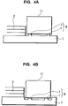
- Figs. 2A and 2B are schematic sectional views of optical interconnection circuit structures according to a first embodiment of the invention.
- a substrate 1 is made of silicon (Si) and a semiconductor light source and a semiconductor light detection device which constitute a semiconductor optical element 11 are optically coupled to an optical waveguide path 2 which is made of silica.
- the optical waveguide path 2 and the optical element 11 having the semiconductor light source, the semiconductor light detection device, etc. are integrated on the substrate 1.
- the optical element 11 having the semiconductor light source, the semiconductor light detection device, etc. is mounted on and secured to a supporting base 8.
- the supporting base 8 is formed at a height which permits the optical waveguide path 2 to coincide in height with an optical axis of the semiconductor optical element 11.
- the supporting base 8 is formed in the desired manner by depositing materials such as dielectrics, metals and semiconductors and the like on the substrate 1 using processes such as sputtering and CVD (chemical vapor deposition) processes and lithographic processes with dry etching processes such as reactive ion etching (RIE), ion beam etching and reactive ion beam etching (RIBE) or wet etching processes such as processes using chemicals.
- RIE reactive ion etching
- RIBE reactive ion beam etching
- wet etching processes such as processes using chemicals.
- a film of materials such as dielectrics, metals and semiconductors having the desired size and height may be bonded onto the substrate 1.
- Fig. 2A shows an example wherein the supporting base 8 is constituted by a single base member
- Fig. 2B shows an example wherein the supporting base is constituted by a plurality of base members 8.
- the shapes of the supporting base 8 may be any of those including rectangular, cubic, cylindrical, conical, truncated conical, and truncated triangular or square pyramid.
- the height of the supporting base 8 may be chosen simply by the alignment with respect to the optical axis of the semiconductor light source 4 and the semiconductor detecting means 5 mounted on the supporting base 8, so that the configuration of the supporting base 8 is not limited to that shown in Figs. 2A and 2B.
- the substrate 1 may be constructed of semiconductor material such as silicon (Si), a dielectric material such as LiNbO3 and glass, or a cell material made of, for example, aluminum nitride.
- the optical waveguide path 2 may employ a dielectric material such as SiO2 and ZnO, an organic material such as polyimide and polysilane, or a semiconductor material such as GaAs and InP.
- Figs. 3A and 3B are schematic sectional views showing optical interconnection circuit structures according to a second embodiment of the invention.
- the supporting base 8 in this embodiment is formed by the same material as that of the optical waveguide path 2.
- the supporting base 8, formed at the same time as the optical waveguide 2 is deposited on the substrate 1 so that the number of fabrication steps can be reduced and greater control of the height of the supporting base can be achieved.
- the material used for the supporting base 8 is the same as the material used for the substrate 1, the optical waveguide path 2, and the semiconductor optical element 11 with the semiconductor light source and the semiconductor detecting device, new problems such as those caused by distortion due to differences in thermal expansion coefficients do not arise and this ensures high reliability and high product yield.
- Fig. 3A shows an arrangement wherein, among the three layers deposited for the optical waveguide 2, namely, the cladding material 21, the core 22 and the second cladding material 23, the cladding material 21 which is first deposited on the substrate 1 is used for the supporting base 8.
- Fig. 3B shows an arrangement wherein all the three layers, namely, the cladding material 21, the core 22 and the cladding material 23 are used for the supporting base 8.
- the portion of the substrate 1 at which the supporting base 8 is formed is arranged to be at a lower level than that of the portion of the substrate at which the optical waveguide path 2 is formed.
- the treating of the portion of the substrate 1 at which the supporting base 8 is formed employs a lithographic process with dry etching processes such as reactive ion etching (RIE), ion beam etching and reactive ion beam etching (RIBE) or wet etching processes such as processes using chemicals.
- RIE reactive ion etching
- RIBE reactive ion beam etching
- the shapes of the supporting base 8 may be any of those including rectangular, cubic, cylindrical, conical, truncated conical, and truncated triangular or square pyramid.
- the height of the supporting base 8 may be chosen simply by the alignment with respect to the optical axis of the semiconductor light source 4 and the semiconductor detecting means 5 mounted on the supporting base 8, so that the configuration of the supporting base 8 is not limited to that shown in Figs. 3A and 3B.
- Figs. 4A and 4B are schematic sectional views of optical interconnection circuit structures according a third embodiment of the invention.
- the supporting base 8 in this embodiment is formed from the same material as the substrate 1.
- the portions of the substrate 1 which form the supporting base 8 are elevated above the portion at which the optical waveguide path 2 is formed.
- the latter portion is etched in advance by using a lithographic process with dry etching processes such as reactive ion etching (RIE), ion beam etching and reactive ion beam etching (RIBE) or wet etching processes such as processes using chemicals.
- RIE reactive ion etching
- RIBE reactive ion beam etching
- wet etching processes such as processes using chemicals.
- the material used for the supporting base 8 is the same as the material used for the substrate 1, the optical waveguide path 2, and the semiconductor optical element 11 with the semiconductor light source 4 and the semiconductor detecting device 5, new problems such as those caused by distortion due to differences in thermal expansion coefficients do not arise, and this ensures high reliability and high product yield. Also, since there is no need to make a separate deposition of materials for the supporting base 8, it is possible to omit a number of the fabrication steps otherwise required.
- the portion of the substrate 1 on which the supporting base 8 is formed is lower than the level of the portion of the substrate at which the optical waveguide path 2 is formed.
- the shapes of the supporting base 8 may be any of those including rectangular, cubic, cylindrical, conical, truncated conical, and truncated triangular or square pyramid.
- the height of the supporting base 8 may be chosen simply by the alignment with respect to the optical axis of the semiconductor light source 4 and the semiconductor detecting means 5 mounted on the supporting base 8, so that the configuration of the supporting base 8 is not limited to that shown in Figs. 4A and 4B.
- Fig. 5 shows, in a schematic sectional view, an optical interconnection circuit structure according to a fourth embodiment of the invention.
- the supporting base 8 in this embodiment is formed from the same material as that of the semiconductor optical element 11 having the semiconductor light source and the semiconductor detecting means.
- the supporting base 8 does not involve any new materials differing from those of the optical waveguide path 2 and the semiconductor optical element 11 with the semiconductor light source and the semiconductor detecting means, so that no new problems such as those caused by distortion due to differences in thermal expansion coefficients arise and this ensures high reliability and high product yield.
- the material of the semiconductor optical element including the semiconductor light source and the semiconductor detecting means can be subjected to crystal growth directly on the supporting base 8 and subsequently the semiconductor optical element can be formed by lithographic and etching processes, the structure thus formed does not require any adjustment in any directions with respect to the optical axis and this enables the number of fabrication steps to be reduced.
- the same material as that for the semiconductor optical element 11 including the semiconductor light source 4 and the semiconductor detecting means 5 is grown by a crystal growth process.
- a film of the same material can be bonded on the substrate 1.
- the shapes of the supporting base 8 may be any of those including rectangular, cubic, cylindrical, conical, truncated conical, and truncated triangular or square pyramid.
- the height of the supporting base 8 may be determined by aligning it with respect to the optical axis of the semiconductor optical element having the semiconductor light source 4 and the semiconductor detecting means 5 mounted on the supporting base 8, so that the configuration of the supporting base 8 is not limited to that of this embodiment.
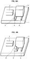
- FIG. 6A and 6B shows, in a perspective view, an optical interconnection structure of a fifth embodiment according to the invention.
- a part of the surface of the supporting base 8 is convex thereby forming a convex portion 9.
- This convex portion 9 serves as a stopper when the semiconductor optical element 11 having the semiconductor light source 4 and the semiconductor detecting means 5 is fixed in place.
- the number of the directions in which the adjustments are made is reduced, which results in the reduction of the number of the fabrication steps otherwise required.
- the side of the semiconductor optical element 11 is in abutment with the stopper formed by the convex portion 9 and the semiconductor optical element 11 does not require any adjustment in height and axial direction.
- Fig. 6B shows an arrangement wherein the stopper is formed by a convex portion 9 which stops the semiconductor optical element 11 in the direction of the optical axis and in directions vertical to the optical axis and horizontal to the surface of the substrate 1.
- the shapes and sizes of the convex portion 9 are not limited to those shown as they may be modified appropriately.
- the convex portion 9 is formed in the desired way by depositing materials such as dielectrics, metals and semiconductors on the supporting base 8 using processes such as sputtering and CVD processes and lithographic processes with dry etching processes such as reactive ion etching (RIE), ion beam etching and reactive ion beam etching (RIBE) or wet etching processes such as processes using chemicals.
- RIE reactive ion etching
- RIBE reactive ion beam etching
- the shapes of the supporting base 8 may be any of those including rectangular, cubic, cylindrical, conical, truncated conical, and truncated triangular or square pyramid.
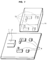
- Fig. 7 shows a perspective view of a sixth embodiment of the optical interconnection circuit structure according to the invention.
- the surfaces of the semiconductor optical element 11 which abut the supporting base 8 are concave thereby forming a recessed portion 13 shaped the same as the abutting surfaces of the supporting base 8.
- the position of the supporting base 8 is fixed simply by having it placed on the supporting base 8. This makes it unnecessary to adjust the semiconductor optical element in the direction of the optical axis and in the directions vertical to the optical axis and horizontal to the surface of the substrate 1. It is thus possible to achieve highly efficient interconnection and to reduce the number of steps required in adjusting the semiconductor optical element with respect to the optical axis.
- the recessed portions 13 may be formed in the desired way by using a lithographic process with dry etching processes such as reactive ion etching (RIE), ion beam etching and reactive ion beam etching (RIBE) or wet etching processes such as processes using chemicals.
- dry etching processes such as reactive ion etching (RIE), ion beam etching and reactive ion beam etching (RIBE) or wet etching processes such as processes using chemicals.
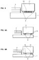
- Fig. 8 shows a schematic sectional view of an optical interconnection structure of a seventh embodiment according to the invention.
- the supporting base 8 is constituted by two upright members and a fixing material 10 is filled in the gap between the two upright members, so that the semiconductor optical element 11 is securely fixed on the supporting base 8. Therefore, in performing the optical coupling between the optical waveguide path 2 and the semiconductor optical element 11 which is determined by the supporting base 8, no displacement of the optical axis occurs and it is possible to fix the coupling of the semiconductor optical element 11 in a highly efficient and very reliable way.
- the fixing material 10 may employ, for example, solder materials such as a mixture of tin and lead, a mixture of gold and lead, or iridium; ultraviolet curing resin; thermometer resin; or thermoplastic resin.
- the process of filling the fixing material 10 into the gap of the supporting base 8 may take place either before or after the semiconductor optical element 11 is mounted thereon.
- the fixing material 10 is filled first, if the amount of such material to be filled in is made larger than the volume corresponding to the gap, the excess amount of such material will flow out of the gap due to the pressure from the semiconductor optical element 11 when it is mounted on the supporting base 8, so that the gap will be completely filled without leaving any space in the supporting base 8.
- the semiconductor optical element 11 is a light emitting element
- the fixing material 10 be a type of solder which dissipates heat effectively.
- Fig. 9A shows a schematic sectional view of an optical interconnection circuit structure of an eighth embodiment according to the invention.
- the semiconductor optical element 11 is fixed to the supporting base 8 with the fixing material 10 applied at contact surfaces of the upright members of the supporting base 8.
- the fixing material 10 may employ, for example, a solder material such as a mixture of tin and lead, a mixture of gold and lead, or iridium; ultraviolet curing resin; thermosetting resin; or thermoplastic resin. If the height of each upright member of the supporting base 8 is appropriately chosen with the thickness of each fixing material 10 taken into account, the optical axis is not displaced in optical coupling relationship between the waveguide 2 and the semiconductor optical element 11. It is therefore possible to achieve highly efficient and reliable coupling of the semiconductor optical element.
- Fig. 9B shows a schematic sectional view of an optical interconnection structure of a ninth embodiment according to the invention.
- each of the upright members of the supporting base 8 has a recessed portion which is filled with the fixing material 10.
- optical interconnection circuit structure As in the present invention, it is possible to obtain simple and highly efficient interconnection between the optical waveguide 2 and the semiconductor optical element 11. It is also possible to obtain an optical interconnection structure which is highly reliable and in which the number of fabrication steps involved is reduced, thus resulting in enhancement of the productivity of the fabrication process.
Landscapes
- Physics & Mathematics (AREA)
- General Physics & Mathematics (AREA)
- Optics & Photonics (AREA)
- Optical Couplings Of Light Guides (AREA)
- Led Device Packages (AREA)
- Light Receiving Elements (AREA)
- Optical Integrated Circuits (AREA)
Applications Claiming Priority (2)
| Application Number | Priority Date | Filing Date | Title |
|---|---|---|---|
| JP3290274A JP2976642B2 (ja) | 1991-11-07 | 1991-11-07 | 光結合回路 |
| JP290274/91 | 1991-11-07 |
Publications (1)
| Publication Number | Publication Date |
|---|---|
| EP0541386A1 true EP0541386A1 (fr) | 1993-05-12 |
Family
ID=17754021
Family Applications (1)
| Application Number | Title | Priority Date | Filing Date |
|---|---|---|---|
| EP92310178A Withdrawn EP0541386A1 (fr) | 1991-11-07 | 1992-11-06 | Structure de circuit d'interconnexion optique |
Country Status (4)
| Country | Link |
|---|---|
| US (1) | US5898806A (fr) |
| EP (1) | EP0541386A1 (fr) |
| JP (1) | JP2976642B2 (fr) |
| AU (1) | AU2823992A (fr) |
Cited By (5)
| Publication number | Priority date | Publication date | Assignee | Title |
|---|---|---|---|---|
| DE4436661A1 (de) * | 1993-10-13 | 1995-04-20 | Mitsubishi Electric Corp | Halbleiterlasermodul und Verfahren zum Zusammenbau des Halbleiterlasermoduls |
| EP0704732A1 (fr) * | 1994-09-28 | 1996-04-03 | Ngk Insulators, Ltd. | Couplage opto-électronique intégré et connecteur |
| EP0961327A1 (fr) * | 1998-05-15 | 1999-12-01 | Nec Corporation | Structure de montage pour un dispositif photo-semiconducteur |
| EP1136863A3 (fr) * | 2000-03-22 | 2002-09-25 | Matsushita Electric Industrial Co., Ltd. | Module comprenant un dispositif à guide d'onde intégré et sa méthode de fabrication |
| EP2496978A4 (fr) * | 2008-06-28 | 2014-04-16 | Kotura Inc | Interface placée entre une source de lumière et un élément optique |
Families Citing this family (53)
| Publication number | Priority date | Publication date | Assignee | Title |
|---|---|---|---|---|
| JP3125385B2 (ja) | 1991-12-12 | 2001-01-15 | 日本電気株式会社 | 光結合回路 |
| JP3474917B2 (ja) * | 1994-04-08 | 2003-12-08 | 日本オプネクスト株式会社 | 半導体装置の製造方法 |
| JPH0996730A (ja) * | 1995-10-02 | 1997-04-08 | Hitachi Ltd | 光素子搭載モジュールおよび光素子搭載方法および光素子搭載モジュールからなる光システム |
| US20060017162A1 (en) * | 1999-03-12 | 2006-01-26 | Shoji Seta | Semiconductor device and manufacturing method of the same |
| JP4270632B2 (ja) * | 1999-03-12 | 2009-06-03 | 株式会社東芝 | ドライエッチングを用いた半導体装置の製造方法 |
| US6849923B2 (en) * | 1999-03-12 | 2005-02-01 | Kabushiki Kaisha Toshiba | Semiconductor device and manufacturing method of the same |
| US6304695B1 (en) * | 1999-05-17 | 2001-10-16 | Chiaro Networks Ltd. | Modulated light source |
| US6366720B1 (en) | 1999-07-09 | 2002-04-02 | Chiaro Networks Ltd. | Integrated optics beam deflector assemblies utilizing side mounting blocks for precise alignment |
| US6344664B1 (en) | 1999-12-02 | 2002-02-05 | Tera Connect Inc. | Electro-optical transceiver system with controlled lateral leakage and method of making it |
| US6404566B1 (en) * | 2000-04-04 | 2002-06-11 | Lucent Technologies Inc. | Apparatus and method for assembling optical devices |
| AU2001278844A1 (en) | 2000-04-26 | 2001-11-07 | Herzel Laor | Configuring optical fibers in a multi-chip module |
| US6547454B2 (en) | 2000-09-21 | 2003-04-15 | Corona Optical Systems, Inc. | Method to align optical components to a substrate and other optical components |
| US6956999B2 (en) | 2001-02-20 | 2005-10-18 | Cyberoptics Corporation | Optical device |
| US20040212802A1 (en) * | 2001-02-20 | 2004-10-28 | Case Steven K. | Optical device with alignment compensation |
| US6546172B2 (en) | 2001-02-20 | 2003-04-08 | Avanti Optics Corporation | Optical device |
| US6546173B2 (en) | 2001-02-20 | 2003-04-08 | Avanti Optics Corporation | Optical module |
| US6443631B1 (en) | 2001-02-20 | 2002-09-03 | Avanti Optics Corporation | Optical module with solder bond |
| BR0205106A (pt) * | 2001-05-09 | 2003-06-17 | Shindengen Electric Mfg | Dispositivo semicondutor e seu método de fabricação |
| JP4779255B2 (ja) * | 2001-07-16 | 2011-09-28 | パナソニック株式会社 | レーザ光源 |
| US20050117904A1 (en) * | 2001-08-01 | 2005-06-02 | Youngwan Choi | Integrated optical transmitter, receiver for free space optical communication and network system and application apparatus thereof |
| JP2003110245A (ja) * | 2001-09-28 | 2003-04-11 | Ibiden Co Ltd | 光学素子実装用基板の製造方法、光学素子実装用基板及び光学素子 |
| US6818464B2 (en) * | 2001-10-17 | 2004-11-16 | Hymite A/S | Double-sided etching technique for providing a semiconductor structure with through-holes, and a feed-through metalization process for sealing the through-holes |
| GB0128616D0 (en) * | 2001-11-29 | 2002-01-23 | Denselight Semiconductors Pte | Standoffs for passive alignment of semiconductor chip and coupling bench |
| US6813023B2 (en) | 2002-01-03 | 2004-11-02 | Chiaro Nerwork Ltd. | Automatic optical inter-alignment of two linear arrangements |
| US6847765B2 (en) * | 2002-03-15 | 2005-01-25 | Agilent Technologies, Inc. | Re-connectable optical interface system and method for optically interconnecting and disconnecting optical devices |
| US6886994B2 (en) * | 2002-07-18 | 2005-05-03 | Chiaro Networks Ltd. | Optical assembly and method for manufacture thereof |
| CN1675572A (zh) * | 2002-08-20 | 2005-09-28 | 赛博光学公司 | 能够调整高度的光学对准安装座 |
| US7229763B2 (en) * | 2003-04-07 | 2007-06-12 | Beckman Coulter, Inc. | Assay system using labeled oligonucleotides |
| US7681306B2 (en) * | 2004-04-28 | 2010-03-23 | Hymite A/S | Method of forming an assembly to house one or more micro components |
| JP2007264441A (ja) * | 2006-03-29 | 2007-10-11 | Fujitsu Ltd | 光結合方法 |
| JP5186785B2 (ja) * | 2007-03-23 | 2013-04-24 | 日本電気株式会社 | 光導波路デバイス、光導波路デバイス用光素子実装システム、光素子実装方法、及びそのプログラム |
| JP4504435B2 (ja) * | 2008-02-15 | 2010-07-14 | 日本電信電話株式会社 | 平面光回路部品及びその作製方法 |
| US9923105B2 (en) | 2013-10-09 | 2018-03-20 | Skorpios Technologies, Inc. | Processing of a direct-bandgap chip after bonding to a silicon photonic device |
| KR101199302B1 (ko) | 2009-10-13 | 2012-11-09 | 한국전자통신연구원 | 광 소자 및 그 제조 방법 |
| US11181688B2 (en) | 2009-10-13 | 2021-11-23 | Skorpios Technologies, Inc. | Integration of an unprocessed, direct-bandgap chip into a silicon photonic device |
| JP5316389B2 (ja) * | 2009-12-07 | 2013-10-16 | 住友ベークライト株式会社 | 光電気複合用基板、光電気複合基板、および光電気複合用基板の製造方法 |
| JP5449041B2 (ja) * | 2010-06-09 | 2014-03-19 | シチズンホールディングス株式会社 | 光デバイスの製造方法 |
| JP5738394B2 (ja) * | 2013-12-24 | 2015-06-24 | シチズンホールディングス株式会社 | 光デバイスの製造方法 |
| US10319693B2 (en) * | 2014-06-16 | 2019-06-11 | Skorpios Technologies, Inc. | Micro-pillar assisted semiconductor bonding |
| US20160291269A1 (en) | 2015-04-01 | 2016-10-06 | Coriant Advanced Technology, LLC | Photonic integrated circuit chip packaging |
| JP6792384B2 (ja) * | 2016-09-08 | 2020-11-25 | 富士通株式会社 | 光モジュール |
| JP6795478B2 (ja) * | 2017-09-22 | 2020-12-02 | 日本電信電話株式会社 | 光接続構造 |
| CN113725725B (zh) | 2017-09-28 | 2025-05-02 | 苹果公司 | 使用量子阱混合技术的激光架构 |
| US11171464B1 (en) | 2018-12-14 | 2021-11-09 | Apple Inc. | Laser integration techniques |
| KR20220024797A (ko) * | 2019-07-25 | 2022-03-03 | 교세라 가부시키가이샤 | 광회로 기판 및 그것을 사용한 전자 부품 실장 구조체 |
| JP2021086976A (ja) * | 2019-11-29 | 2021-06-03 | セーレンKst株式会社 | 合成光生成装置及びその製造方法 |
| JP2022160196A (ja) * | 2021-04-06 | 2022-10-19 | セーレンKst株式会社 | 合成光生成装置 |
| US12204155B2 (en) * | 2021-09-24 | 2025-01-21 | Apple Inc. | Chip-to-chip optical coupling for photonic integrated circuits |
| US20230176196A1 (en) * | 2021-12-08 | 2023-06-08 | Beijing Voyager Technology Co., Ltd. | Submount for a transmitter of an optical sensing system including a pair of co-packaged laser bars |
| US12426139B1 (en) | 2022-06-27 | 2025-09-23 | Apple Inc. | Feedback control of a diode element |
| WO2024150629A1 (fr) * | 2023-01-13 | 2024-07-18 | イビデン株式会社 | Carte de câblage |
| CN120303595A (zh) * | 2023-01-13 | 2025-07-11 | 揖斐电株式会社 | 布线基板 |
| WO2024232820A1 (fr) * | 2023-05-09 | 2024-11-14 | National University Of Singapore | Ensemble pour alignement submicronique et procédé d'alignement submicronique utilisant l'ensemble |
Citations (3)
| Publication number | Priority date | Publication date | Assignee | Title |
|---|---|---|---|---|
| EP0171615A2 (fr) * | 1984-08-10 | 1986-02-19 | Nippon Telegraph and Telephone Corporation | Circuit intégré optique hybride et son procédé de fabrication |
| GB2213957A (en) * | 1987-12-15 | 1989-08-23 | Stc Plc | Waveguide to opto-electronic transducer coupling |
| US5023881A (en) * | 1990-06-19 | 1991-06-11 | At&T Bell Laboratories | Photonics module and alignment method |
Family Cites Families (13)
| Publication number | Priority date | Publication date | Assignee | Title |
|---|---|---|---|---|
| US4005312A (en) * | 1973-11-08 | 1977-01-25 | Lemelson Jerome H | Electro-optical circuits and manufacturing techniques |
| US4149088A (en) * | 1975-03-06 | 1979-04-10 | Lemelson Jerome H | Electro-optical circuits and manufacturing |
| US4237474A (en) * | 1978-10-18 | 1980-12-02 | Rca Corporation | Electroluminescent diode and optical fiber assembly |
| US4699449A (en) * | 1985-03-05 | 1987-10-13 | Canadian Patents And Development Limited-Societe Canadienne Des Brevets Et D'exploitation Limitee | Optoelectronic assembly and method of making the same |
| DE3735455A1 (de) * | 1987-03-18 | 1988-09-29 | Telefonbau & Normalzeit Gmbh | Elektrische bauelemente |
| GB2208943B (en) * | 1987-08-19 | 1991-07-31 | Plessey Co Plc | Alignment of fibre arrays |
| US4904036A (en) * | 1988-03-03 | 1990-02-27 | American Telephone And Telegraph Company, At&T Bell Laboratories | Subassemblies for optoelectronic hybrid integrated circuits |
| US5081520A (en) * | 1989-05-16 | 1992-01-14 | Minolta Camera Kabushiki Kaisha | Chip mounting substrate having an integral molded projection and conductive pattern |
| JPH0797649B2 (ja) * | 1990-03-07 | 1995-10-18 | 三菱電機株式会社 | 半導体圧力センサ装置およびその製造方法 |
| US5113404A (en) * | 1990-07-05 | 1992-05-12 | At&T Bell Laboratories | Silicon-based optical subassembly |
| US5077878A (en) * | 1990-07-11 | 1992-01-07 | Gte Laboratories Incorporated | Method and device for passive alignment of diode lasers and optical fibers |
| JP2762792B2 (ja) * | 1991-08-30 | 1998-06-04 | 日本電気株式会社 | 光半導体装置 |
| KR100280762B1 (ko) * | 1992-11-03 | 2001-03-02 | 비센트 비.인그라시아 | 노출 후부를 갖는 열적 강화된 반도체 장치 및 그 제조방법 |
-
1991
- 1991-11-07 JP JP3290274A patent/JP2976642B2/ja not_active Expired - Lifetime
-
1992
- 1992-11-06 EP EP92310178A patent/EP0541386A1/fr not_active Withdrawn
- 1992-11-09 AU AU28239/92A patent/AU2823992A/en not_active Abandoned
-
1996
- 1996-12-20 US US08/772,098 patent/US5898806A/en not_active Expired - Lifetime
Patent Citations (3)
| Publication number | Priority date | Publication date | Assignee | Title |
|---|---|---|---|---|
| EP0171615A2 (fr) * | 1984-08-10 | 1986-02-19 | Nippon Telegraph and Telephone Corporation | Circuit intégré optique hybride et son procédé de fabrication |
| GB2213957A (en) * | 1987-12-15 | 1989-08-23 | Stc Plc | Waveguide to opto-electronic transducer coupling |
| US5023881A (en) * | 1990-06-19 | 1991-06-11 | At&T Bell Laboratories | Photonics module and alignment method |
Non-Patent Citations (1)
| Title |
|---|
| PATENT ABSTRACTS OF JAPAN vol. 13, no. 98 (P-840)(3446) 8 March 1989 & JP-A-63 280 206 ( NEC CORP. ) * |
Cited By (10)
| Publication number | Priority date | Publication date | Assignee | Title |
|---|---|---|---|---|
| DE4436661A1 (de) * | 1993-10-13 | 1995-04-20 | Mitsubishi Electric Corp | Halbleiterlasermodul und Verfahren zum Zusammenbau des Halbleiterlasermoduls |
| US5659566A (en) * | 1993-10-13 | 1997-08-19 | Mitsubishi Denki Kabushiki Kaisha | Semiconductor laser module and method of assembling semiconductor laser module |
| EP0704732A1 (fr) * | 1994-09-28 | 1996-04-03 | Ngk Insulators, Ltd. | Couplage opto-électronique intégré et connecteur |
| EP1143278A3 (fr) * | 1994-09-28 | 2002-03-20 | Ngk Insulators, Ltd. | Couplage opto-électronique intégré et connecteur |
| EP0961327A1 (fr) * | 1998-05-15 | 1999-12-01 | Nec Corporation | Structure de montage pour un dispositif photo-semiconducteur |
| US6184560B1 (en) | 1998-05-15 | 2001-02-06 | Nec Corporation | Photosemiconductor device mounted structure |
| EP1136863A3 (fr) * | 2000-03-22 | 2002-09-25 | Matsushita Electric Industrial Co., Ltd. | Module comprenant un dispositif à guide d'onde intégré et sa méthode de fabrication |
| US6614966B2 (en) | 2000-03-22 | 2003-09-02 | Matsushita Electric Industrial Co., Ltd. | Optical waveguide device integrated module and method of manufacturing the same |
| US6621962B2 (en) | 2000-03-22 | 2003-09-16 | Matsushita Electric Industrial Co., Ltd. | Optical waveguide device integrated module and method of manufacturing the same |
| EP2496978A4 (fr) * | 2008-06-28 | 2014-04-16 | Kotura Inc | Interface placée entre une source de lumière et un élément optique |
Also Published As
| Publication number | Publication date |
|---|---|
| JP2976642B2 (ja) | 1999-11-10 |
| US5898806A (en) | 1999-04-27 |
| JPH05196844A (ja) | 1993-08-06 |
| AU2823992A (en) | 1993-05-13 |
Similar Documents
| Publication | Publication Date | Title |
|---|---|---|
| US5898806A (en) | Optical interconnection circuit structure | |
| US7298941B2 (en) | Optical coupling to IC chip | |
| US5854867A (en) | Optical module having lenses aligned on lens-positioning V-groove and fabrication method thereof | |
| US5627931A (en) | Optoelectronic transducer | |
| US5771322A (en) | Light-receiving structure for wave-guide type optical devices | |
| EP0826995B1 (fr) | Module optoélectronique ayant ses composants montés sur un élément de montage unique | |
| KR19980703337A (ko) | 광전자/마이크로웨이브 회로용 기판 시스템 | |
| US5705025A (en) | Method for dry etching of a semiconductor substrate | |
| EP0893720B1 (fr) | Un micromodule photonique avec une cloison de séparation | |
| US5808293A (en) | Photo detector with an integrated mirror and a method of making the same | |
| US5771323A (en) | Micro-photonics module | |
| EP0218624B1 (fr) | Ameliorations a des agencements optiques de connexion | |
| US5862283A (en) | Mounting a planar optical component on a mounting member | |
| US6907178B2 (en) | Optoelectronic assembly with embedded optical and electrical components | |
| US5522000A (en) | Providing optical coupling with single crystal substrate mounted electro-optic transducers | |
| US7349603B2 (en) | Optical arrangement with two optical inputs/outputs and production methods | |
| AU9704098A (en) | Optical interconnection circuit structure | |
| KR100271826B1 (ko) | 레이저 다이오드 칩과 광 파이버의 정열방법 | |
| US12038610B2 (en) | Wafer-level optoelectronic packaging | |
| EP1189087A2 (fr) | Récepteur photonique monolithique comprenant un support de fibre autoaligné adapté pour assemblage du type flip chip | |
| JP2000507713A (ja) | 少なくとも1つの光電子素子および1つの導波路をハイブリッド集積する方法、並びに集積された電気―光学デバイス | |
| US20050205762A1 (en) | Integrated optical transceiver and related methods | |
| US7842914B2 (en) | Optoelectronic package, camera including the same and related methods | |
| EP1269239A2 (fr) | Emetteur-recepteur optique integre et procedes connexes | |
| KR0173912B1 (ko) | 광도파로와 입출력단 단일모드 광섬유의 광접속장치 및 그의 제조방법 |
Legal Events
| Date | Code | Title | Description |
|---|---|---|---|
| PUAI | Public reference made under article 153(3) epc to a published international application that has entered the european phase |
Free format text: ORIGINAL CODE: 0009012 |
|
| 17P | Request for examination filed |
Effective date: 19930119 |
|
| AK | Designated contracting states |
Kind code of ref document: A1 Designated state(s): DE FR GB IT NL SE |
|
| 17Q | First examination report despatched |
Effective date: 19950419 |
|
| 18D | Application deemed to be withdrawn |
Effective date: 19950830 |