EP0541630B1 - Dispositif de refroidissement de profiles extrudes - Google Patents
Dispositif de refroidissement de profiles extrudes Download PDFInfo
- Publication number
- EP0541630B1 EP0541630B1 EP91913850A EP91913850A EP0541630B1 EP 0541630 B1 EP0541630 B1 EP 0541630B1 EP 91913850 A EP91913850 A EP 91913850A EP 91913850 A EP91913850 A EP 91913850A EP 0541630 B1 EP0541630 B1 EP 0541630B1
- Authority
- EP
- European Patent Office
- Prior art keywords
- jet
- jets
- air
- cooling
- nozzles
- Prior art date
- Legal status (The legal status is an assumption and is not a legal conclusion. Google has not performed a legal analysis and makes no representation as to the accuracy of the status listed.)
- Expired - Lifetime
Links
Images


Classifications
-
- B—PERFORMING OPERATIONS; TRANSPORTING
- B21—MECHANICAL METAL-WORKING WITHOUT ESSENTIALLY REMOVING MATERIAL; PUNCHING METAL
- B21C—MANUFACTURE OF METAL SHEETS, WIRE, RODS, TUBES, PROFILES OR LIKE SEMI-MANUFACTURED PRODUCTS OTHERWISE THAN BY ROLLING; AUXILIARY OPERATIONS USED IN CONNECTION WITH METAL-WORKING WITHOUT ESSENTIALLY REMOVING MATERIAL
- B21C29/00—Cooling or heating extruded work or parts of the extrusion press
-
- C—CHEMISTRY; METALLURGY
- C21—METALLURGY OF IRON
- C21D—MODIFYING THE PHYSICAL STRUCTURE OF FERROUS METALS; GENERAL DEVICES FOR HEAT TREATMENT OF FERROUS OR NON-FERROUS METALS OR ALLOYS; MAKING METAL MALLEABLE, e.g. BY DECARBURISATION OR TEMPERING
- C21D1/00—General methods or devices for heat treatment, e.g. annealing, hardening, quenching or tempering
- C21D1/62—Quenching devices
- C21D1/667—Quenching devices for spray quenching
-
- B—PERFORMING OPERATIONS; TRANSPORTING
- B05—SPRAYING OR ATOMISING IN GENERAL; APPLYING FLUENT MATERIALS TO SURFACES, IN GENERAL
- B05B—SPRAYING APPARATUS; ATOMISING APPARATUS; NOZZLES
- B05B1/00—Nozzles, spray heads or other outlets, with or without auxiliary devices such as valves, heating means
- B05B1/14—Nozzles, spray heads or other outlets, with or without auxiliary devices such as valves, heating means with multiple outlet openings; with strainers in or outside the outlet opening
- B05B1/20—Perforated pipes or troughs, e.g. spray booms; Outlet elements therefor
- B05B1/202—Perforated pipes or troughs, e.g. spray booms; Outlet elements therefor comprising inserted outlet elements
-
- B—PERFORMING OPERATIONS; TRANSPORTING
- B05—SPRAYING OR ATOMISING IN GENERAL; APPLYING FLUENT MATERIALS TO SURFACES, IN GENERAL
- B05B—SPRAYING APPARATUS; ATOMISING APPARATUS; NOZZLES
- B05B9/00—Spraying apparatus for discharge of liquids or other fluent material, without essentially mixing with gas or vapour
- B05B9/03—Spraying apparatus for discharge of liquids or other fluent material, without essentially mixing with gas or vapour characterised by means for supplying liquid or other fluent material
- B05B9/035—Spraying apparatus for discharge of liquids or other fluent material, without essentially mixing with gas or vapour characterised by means for supplying liquid or other fluent material to several spraying apparatus
Definitions
- the invention relates to a device for cooling extruded profiles with an upper air nozzle arranged above an outlet path of the extruded profile with a slit-shaped nozzle opening and with offset below the outlet path in the direction of transport in relation to the upper nozzle and arranged at a smaller distance from the extruded profile than the upper nozzle lower air nozzles.
- Extruded profiles must be cooled down after leaving the press die. This applies in particular to extruded profiles made of light metal alloys.
- the required temperature / time gradients are between 3 and 5 ° K / s for AlMgSi alloys and up to 50 ° K / s for high-strength alloys, e.g. Aviation materials.
- the required high cooling rates can be achieved by pulling the strands through a standing water wave or also by cooling the extruded profiles in so-called water boxes ", the walls of which are provided with spray nozzles.
- the necessary cooling rates are achieved in view of the metallurgical requirements however, the very rapid cooling, which is not uniform over the circumference, deforms the extruded profiles, which means that a lot of communication is often required.
- the currently available water cooling devices it is hardly possible to influence the cooling effect in a targeted manner.
- the use of cooling water is not least because of the associated cooling water treatment always economically much more expensive than the simple cooling with ambient air, which is also possible in principle, so that the aim is to have as many extruded profiles as possible e e.g. also light metal extruded profiles with reduced wall thickness, to be cooled only with air.
- the compressed air is directed from below through individual air spray nozzles onto the extrusion pieces.
- the extrusion profiles are cut into pieces and then conveyed on a transporter conveying transversely to the exit direction with their longitudinal axes parallel to the longitudinal axis of the upper slot nozzle under this slot nozzle. Due to this known type of cooling, the extrusion pieces are only uniformly charged with cooling air from above if their profile is not significantly wider than the slot-shaped opening of the upper nozzle. Adequate cooling is also only ensured if the extrusion pieces are each kept below the upper nozzle for a certain time. For this reason and because of the individual spray nozzles arranged below the transport plane, neither sufficient nor uniform exposure to cooling air of a continuously transported extruded profile is possible.
- the conventional air cooling devices cannot achieve the high cooling speeds required for metallurgical reasons, but are only suitable for cooling the extruded profiles to a temperature which allows the handling required for the further production process, namely cutting, straightening, packaging, etc.
- the invention is therefore based on the object of providing a device for cooling extruded profiles of the type specified, in which the disadvantages mentioned above do not occur.
- a device which, on the one hand, achieves the high cooling speeds required for metallurgical reasons and, on the other hand, reliably avoids warping of the extruded profiles during the cooling process.
- the cooling effect should be adjustable and thus adaptable to the respective requirements of the extruded profiles to be cooled.
- the advantages achieved by the invention are based initially on the use of ambient air, which is available in practically unlimited quantities, as the cooling medium, so that the problems associated with the treatment of cooling water are eliminated.
- a particularly expedient design of the nozzles ensures that, despite the cooling medium “ambient air”, which has a lower heat dissipation capacity in comparison with cooling water, the cooling rates required for metallurgical reasons are achieved.
- the cooling rate can be set precisely locally and thereby adapted to different extrusion profiles.
- a combination with water cooling is also possible for special cases.
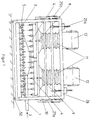
- the device for cooling extruded profiles which is shown in the figures and is generally indicated by reference number 10, has a transport device for the extruded profiles 1, namely a roller conveyor 3, in order to convey the extruded profiles 1 in the direction of arrow 2 through the device 10.
- lower nozzles 5 are attached, which blow the extruded profile 1 from below.
- the lower nozzles 5 are designed to be stationary, but can also be attached to be vertically movable if necessary.
- Upper nozzles 4 are mounted above the roller conveyor 3, at such a distance above the roller conveyor 3 that even the highest profiles can pass the clear height between the roller conveyor 3 and nozzles 4.
- the upper nozzles 4 are offset from the lower nozzles 5 by half a division of the roller conveyor 3, so that the air flow blown onto the extruded profile 1 by means of the nozzles 3 and 4 does not interfere with one another, but can flow largely undisturbed upwards and downwards, as is made visible in FIG. 4 by indicating the direction of flow.
- An upper nozzle 4 is opposite a roller of the roller conveyor 3, while each lower nozzle blows into the space between two upper nozzles.
- blowing air from the upper nozzles 4 nestles around the rollers of the roller table 3 and then flows downward, while the blowing air from the lower nozzles 5 undisturbed upwards into the space flows out between the upper nozzles 4.
- the distance between the upper nozzles 4 from the roller conveyor 3 or from the extruded profiles 1 is greater than the distance from the lower nozzles 5 from the extruded profile 1;
- the nozzle slots of the upper nozzles 4 are kept wider than the nozzle slots of the lower nozzles 5, so that despite the greater distance of the upper nozzles 4 from the extruded profiles 1, the core jet of the rays of the upper ones Nozzles 4 fully impact the extruded profile 1; as a result, at the same nozzle pressure for the upper and lower nozzles 4, 5, the arrival speed of the flow at the surface of the extruded profiles 1 for the upper and lower nozzles 4, 5 can be kept approximately the same, which results in achieving approximately the same heat transfer with the upper and lower Nozzles 4, 5 is important.
- the slot nozzles of the upper and lower nozzle ribs 4, 5 are arranged transversely to the pressing and transport direction of the extruded profiles 1, which is indicated by the arrow 2. This ensures that the entire circumference of the extruded profile 1 is always evenly blown and the flow from the area 6, where it strikes the surface of the extruded profile 1 (see FIG. 4), always flows in the direction of the generatrix of the extruded profile 1.
- the area 6 lies in the axial direction for the upper nozzles 4 below and for the lower nozzles 5 above the nozzle openings on the profile surface.
- the extruded profile 1 is thus moved through the accumulation zone 7 (see FIG. 4) which forms between two adjacent slot nozzles of the nozzle ribs 4, 5. If the period of time that the extruded profile 1 takes to go through half the division of the nozzles 4, 5, is sufficiently small, which is always the case with a nozzle division of the order of about 100 mm to 200 mm and the usual pressing speeds, the reduction in the heat transfer in the storage zone 7 has no effect, ie the profile is cooled uniformly and continuously, as is absolutely necessary for metallurgical reasons.
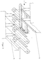
- the upper nozzle field is divided into two sub-fields of equal size, each of which is supplied by a double-flow radial fan 12 arranged above the nozzle field and blowing downwards.
- the two upper nozzle boxes of the two subfields can be adjusted separately or together vertically in the vertical direction in the direction of the double arrows 9.
- the nozzle boxes are connected to the radial fans 12 via bellows 11, which enable the required change in distance between the nozzle box and the radial fan 12.
- the common vertical adjusting device for adapting to extruded profiles of different heights is indicated by four lifting spindles 25a, which are supported on the one hand on the frame 26 of the device 10 and on the other hand are connected to a vertically movable frame 27a which in turn carries the bellows 11 or the nozzle boxes.
- the lifting spindles 25a By vertical adjustment of the lifting spindles 25a, the bellows 11 and the nozzle boxes can also be adjusted vertically with respect to the roller conveyor 3.
- pneumatic cylinders 25b can also be used be provided which, for triggering the rapid lift for both nozzle boxes, generate separate movement superimposed on the common lift and are actuated by switching means such as contact switches or light barriers.
- the two bellows 11 and thus the associated subfields are adjusted together by means of the frame 27a.
- the pneumatic cylinders 25b attached to the frame 27a actuate the carriages 27b, with the aid of which e.g. the nozzle boxes are moved over chains or ropes.
- the entire device 10 is located in the frame 26, which can be moved in and out of the pressing line transversely to the pressing direction by means of wheels 50 and a conventional travel drive (see FIG. 2). In this way, a simple exchange of the cooling device 10 for another embodiment is possible if this is necessary for production reasons.
- the lower nozzles 5 are fed by a radial fan 8, which is located laterally next to the lower nozzle ribs 5 or the roller conveyor 3 outside the frame 26.
- a radial fan 8 which is located laterally next to the lower nozzle ribs 5 or the roller conveyor 3 outside the frame 26.
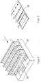
- FIG. 5 shows, using the example of a section of a nozzle field, how the heat transfer of this nozzle field can be changed transversely to the direction of movement 2 of the extruded profile 1 and thus over the profile width.
- the nozzle array is divided into five sections evenly across the width.
- the cooling air supply to each section can be adjusted by means of nozzle slides 28 which can be displaced in the longitudinal direction, that is to say parallel to the movement arrow 2 and which are integrated in the nozzle boxes 29 of the lower nozzle rib 5 shown.
- FIG. 6 shows such a nozzle slide 28, in which the heat transfer can be adjusted in stages from 100% to 25% depending on the area which is pushed in front of the nozzle inlet.
- These sliders 28, which can be adjusted by remote control and whose positioning can also be controlled by a computer, enable the cooling effect to be adapted depending on the requirements of the extruded profile 1. In this way, areas of the extruded profile 1 with material accumulations can be cooled more strongly than areas of the extruded profile 1 with reduced wall thickness. This ensures that the extruded profile 1 remains straight during cooling and bending of the profile during cooling is avoided, which would require a lot of communication and would also lead to considerable rejects.
- nozzle slide As can be seen in Fig. 6, 28 different openings are provided in the nozzle slide, namely a large opening that extends almost over the entire width of the nozzle slide 28, which allows maximum cooling air passage and thus a heat transfer of 100%, and three further sequences of openings, each with a smaller diameter, which enable the indicated heat transfers of 75%, 50% and 25%, in each case based on the maximum heat transfer of 100%.
- a slot nozzle 30 is shown schematically, in which a nozzle assembly 31 with water nozzles 32 is installed.
- the cooling device according to FIGS. 1 to 4 can also be provided with two-phase cooling, namely air / water mixture cooling.
- the water nozzle sticks 31 can be moved back and forth in the air nozzles 30, as is indicated in FIG. 8 by the double arrow.
- the water nozzles 32 are fastened to a one which forms the water nozzle stick 31, through which water with the water pressure p flows on the one hand and on the other hand is moved back and forth by an electric motor with camshaft 34 in the direction of the double arrow 33.
- the amplitude of the back and forth movement corresponds to a multiple of half Division of the water nozzles in the direction transverse to the pressing and outlet direction 2 of the profile 1.
- the water nozzle stick 31 formed by a tube with nozzles 32 is divided into several areas 31a, 31b, and 31c, which have different areas Water pressures p1, p2 and p3 are applied. As a result, the density of water under the nozzles 32 changes in the respective areas.
- FIG. 10 shows a highly schematic view of a cooling device 10 seen in the pressing direction, in which the extruded profile 1 is blown by the lower nozzle field 5 and by two upper nozzle fields 4r and 41, namely a right-hand partial field 4r and a left-hand partial field 41 Subfields can be pivoted about associated axes 20r and 201, as indicated by the associated rotary arrows 21r and 211.
- the cooling effect can also be adapted to angular profile cross sections in a particularly simple and therefore inexpensive manner, as shown in the example in FIG. 10.
- the axes 201 and 20r can be swiveled around the nozzle fields 41, 4r and also adjusted in height.
- the air supply to the nozzle boxes of the two subfields 41, 4r takes place by means of flexible connections or lines.
Landscapes
- Chemical & Material Sciences (AREA)
- Engineering & Computer Science (AREA)
- Mechanical Engineering (AREA)
- Materials Engineering (AREA)
- Thermal Sciences (AREA)
- Crystallography & Structural Chemistry (AREA)
- Physics & Mathematics (AREA)
- Metallurgy (AREA)
- Organic Chemistry (AREA)
- Extrusion Of Metal (AREA)
- Physical Vapour Deposition (AREA)
- Heat Treatments In General, Especially Conveying And Cooling (AREA)
- Extrusion Moulding Of Plastics Or The Like (AREA)
Abstract
Claims (13)
- Dispositif de refroidissement de profilés extrudés,a) comportant une buse à air (4) supérieure à ouverture en forme de fente, disposée au-dessus d'une piste de sortie du profilé extrudé (1), etb) comportant en dessous de la piste de sortie des buses à air (5) inférieures, décalées par rapport à la buse supérieure (4) dans le sens du transport, et disposées à une distance du profilé extrudé (1) plus petite que la buse supérieure (4),
caractérisé en ce quec) plusieurs buses à air (4) supérieures sont disposées l'une derrière l'autre dans le sens du transport du profilé extrudé (1) et sont chacune décalées d'un demi-intervalle par rapport aux buses inférieures (5),d) les buses inférieures (5) présentent des ouvertures en forme de fente avec une largeur de fente inférieure à celle des buses supérieures (4), ete) les ouvertures des buses supérieures et inférieures (4,5) s'étendent transversalement par rapport à la direction d'extrusion et de sortie (2) du profilé extrudé (1). - Dispositif selon la revendication 1, caractérisé en ce que les corps de buse des buses à air (4, 5) sont dotés de dispositifs pour la modification de la pression de buse dans au moins deux tronçons des buses à air (4, 5) situés suivant la longueur des fentes des buses, c'est-à-dire transversalement à la direction d'extrusion et de transport (2) du profilé extrudé (1).
- Dispositif selon la revendication 2, caractérisé en ce que les dispositifs pour la modification de la pression de buse sont formés par des plaques coulissantes (28) pouvant être déplacées transversalement par rapport à l'axe longitudinal des fentes des buses, et qui lors de leur déplacement dans le sens de leur longueur réduisent différemment dans la section transversale de traversée l'écoulement de l'air vers les fentes de buse, par des perforations variant suivant la longueur des plaques coulissantes (28).
- Dispositif selon l'une des revendications 1 à 3, caractérisé en ce que la piste de sortie est formée par une piste à rouleaux (3), et en ce que les buses à air (5) inférieures sont disposées exactement, ou au moins à peu près exactement, entre les rouleaux de la piste à rouleaux, les buses à air (4) supérieures étant disposées exactement ou à peu près exactement au-dessus des rouleaux de la piste à rouleaux (3).
- Dispositif selon l'une des revendications 1 à 4, caractérisé en ce que les buses à air (4) supérieures peuvent être ajustées en hauteur ensemble avec leur caisson à buses servant à l'alimentation en air, pour la modification de leur distance par rapport au profilé extrudé (1).
- Dispositif selon l'une des revendications 1 à 5, caractérisé par un dispositif de levage rapide des buses (4) supérieures, et par un dispositif de commande pour lancer le levage rapide.
- Dispositif selon l'une des revendications 1 à 6, caractérisé par des ventilateurs radiaux (8, 12) pour l'alimentation des buses à air (4, 5).
- Dispositif selon l'une des revendications 1 à 7, caractérisé en ce que dans les champs de buses à air (4, 5) situés au-dessus et en dessous du profilé extrudé (1), sont disposées des buses à eau (31, 32) pour le renforcement de l'effet de refroidissement.
- Dispositif selon la revendication 8, caractérisé en ce que les buses à eau (32) sont montées sur des cannes à buses (31) installées dans les corps (30) des buses à air.
- Dispositif selon l'une des revendications 8 ou 9, caractérisé en ce que les buses à eau (31, 32) peuvent, avec les cannes à buses (31) qui les portent, être déplacées en va-et-vient transversalement à la direction d'extrusion et de sortie (2) du profilé extrudé (1).
- Dispositif selon l'une des revendications 8 à 10, caractérisé en ce que les cannes à buses (31) des buses à eau (31, 32) sont partagées en au moins deux tronçons qui peuvent être alimentés sous une pression d'eau différente et/ou par des débits d'eau différents.
- Dispositif selon l'une des revendications 8 à 11, caractérisé en ce que le champ supérieur de buses (4) est partagé dans le plan vertical longitudinal médian, en ce que les deux parties (4r, 41) du champ supérieur de buses (4) sont maintenues à rotation sur leur bord extérieur autour d'axes (20r, 201) qui s'étendent dans la direction d'extrusion et de sortie (2) du profilé extrudé (1), en ce que chaque champ partiel de buses (4r, 41) peut être incliné dans une direction verticale ou pratiquement verticale par un déplacement de rotation allant du milieu vers l'extérieur.
- Dispositif selon la revendication 12, caractérisé en ce que pour l'adaptation en hauteur des deux champs partiels supérieurs de buses (4r, 41) à la forme du profilé extrudé (1), les positions verticales des axes latéraux (20r, 201) sont ajustables.
Priority Applications (1)
| Application Number | Priority Date | Filing Date | Title |
|---|---|---|---|
| AT91913850T ATE104179T1 (de) | 1990-08-02 | 1991-07-30 | Vorrichtung zur abkuehlung von strangpressprofilen. |
Applications Claiming Priority (3)
| Application Number | Priority Date | Filing Date | Title |
|---|---|---|---|
| DE4024605A DE4024605A1 (de) | 1990-08-02 | 1990-08-02 | Vorrichtung zur abkuehlung von strangpressprofilen |
| DE4024605 | 1990-08-02 | ||
| PCT/EP1991/001425 WO1992002316A1 (fr) | 1990-08-02 | 1991-07-30 | Dispositif de refroidissement de profiles extrudes |
Publications (2)
| Publication Number | Publication Date |
|---|---|
| EP0541630A1 EP0541630A1 (fr) | 1993-05-19 |
| EP0541630B1 true EP0541630B1 (fr) | 1994-04-13 |
Family
ID=6411548
Family Applications (1)
| Application Number | Title | Priority Date | Filing Date |
|---|---|---|---|
| EP91913850A Expired - Lifetime EP0541630B1 (fr) | 1990-08-02 | 1991-07-30 | Dispositif de refroidissement de profiles extrudes |
Country Status (7)
| Country | Link |
|---|---|
| US (1) | US5327763A (fr) |
| EP (1) | EP0541630B1 (fr) |
| JP (1) | JP3066075B2 (fr) |
| CA (1) | CA2088487C (fr) |
| DE (2) | DE4024605A1 (fr) |
| ES (1) | ES2054500T3 (fr) |
| WO (1) | WO1992002316A1 (fr) |
Cited By (2)
| Publication number | Priority date | Publication date | Assignee | Title |
|---|---|---|---|---|
| DE19649073C2 (de) * | 1996-11-28 | 2000-12-07 | Carl Kramer | Vorrichtung zur Abkühlung von Strangpreßprofilen |
| DE102016102093B3 (de) * | 2016-02-05 | 2017-06-14 | Bwg Bergwerk- Und Walzwerk-Maschinenbau Gmbh | Durchlaufkühlvorrichtung und Verfahren zum Abkühlen eines Metallbandes |
Families Citing this family (30)
| Publication number | Priority date | Publication date | Assignee | Title |
|---|---|---|---|---|
| CH686072A5 (de) * | 1992-06-19 | 1995-12-29 | Alusuisse Lonza Services Ag | Sprayanlage zum Kuhlen von Profilen. |
| DE4234285A1 (de) * | 1992-10-10 | 1994-04-14 | Heimsoth Verwaltungen | Verfahren zur Wärmebehandlung von metallischem Gut |
| JPH08509660A (ja) * | 1993-02-18 | 1996-10-15 | エス エム エス ハーゼンクレヴァー ゲゼルシャフト ミット ベシュレンクテル ハフツング | 押出しプレスのために規定された金属鋳塊に温度プロフィルを賦与する方法と装置 |
| FR2738577B1 (fr) * | 1995-09-12 | 1998-03-13 | Selas Sa | Dispositif de refroidissement d'un produit lamine |
| DE29603022U1 (de) * | 1996-02-21 | 1996-04-18 | Ipsen Industries International GmbH, 47533 Kleve | Vorrichtung zum Abschrecken metallischer Werkstücke |
| DE19810215A1 (de) * | 1998-03-10 | 1999-09-16 | Schloemann Siemag Ag | Kühlschacht für einen Rollgang |
| NO20011301L (no) * | 2001-03-14 | 2002-09-16 | Norsk Hydro As | Metode og utstyr for kjöling av profiler etter ekstrudering |
| JP2002275603A (ja) * | 2001-03-16 | 2002-09-25 | Kobe Steel Ltd | 熱処理型アルミニウム合金押出材のプレス焼入れ方法及びプレス焼入れ用冷却装置 |
| DE10215229A1 (de) * | 2002-04-06 | 2003-10-16 | Sms Demag Ag | Vorrichtung zum Kühlen von Walzgut innerhalb der Kühlstrecke einer Walzanlage |
| DE10258553B8 (de) * | 2002-12-14 | 2005-12-08 | Leica Mikrosysteme Gmbh | Verfahren zum automatischen Annähern eines Präparates an ein Messer eines Mikrotoms oder Ultramikrotoms |
| DE10311169A1 (de) * | 2003-03-12 | 2004-09-23 | Sms Eumuco Gmbh | Vorrichtung zum Strangpressen von gekrümmten Strangpreßprofilen |
| US20040206148A1 (en) * | 2003-04-16 | 2004-10-21 | Akira Miyazaki | Cooling method and cooling equipment of extruded article |
| DE20308237U1 (de) | 2003-05-21 | 2003-09-18 | Unterschütz Sondermaschinenbau GmbH, 06333 Walbeck | Wechselvorrichtung zur Kühlung der Pressstränge zwischen den Medien Luft und Wasser hinter der Strangpresse |
| US7096705B2 (en) * | 2003-10-20 | 2006-08-29 | Segal Vladimir M | Shear-extrusion method |
| KR101186761B1 (ko) | 2006-08-28 | 2012-10-08 | 에어 프로덕츠 앤드 케미칼스, 인코오포레이티드 | 극저온 액체 분사용 분사 장치 및 이 장치와 관련된 분사 방법 |
| MX2010002065A (es) * | 2007-08-28 | 2010-03-15 | Air Prod & Chem | Aparato y metodo para supervisar y regular el enfriamiento criogenico. |
| MX2010002067A (es) | 2007-08-28 | 2010-05-21 | Air Prod & Chem | Aparato y metodo para controlar la temperatura de un criogeno. |
| US20110036555A1 (en) * | 2007-08-28 | 2011-02-17 | Air Products And Chemicals, Inc. | Method and apparatus for discharging a non-linear cryogen spray across the width of a mill stand |
| CN101842629A (zh) * | 2007-08-28 | 2010-09-22 | 气体产品与化学公司 | 用于在低温构件上提供无冷凝液和无霜表面的设备和方法 |
| CN101468365B (zh) * | 2007-12-29 | 2011-03-30 | 富准精密工业(深圳)有限公司 | 导风装置和采用该导风装置的工件冷却装置 |
| CN101850604A (zh) * | 2010-05-18 | 2010-10-06 | 昆山科信橡塑机械有限公司 | 物料吹干机 |
| CN102785123A (zh) * | 2011-05-20 | 2012-11-21 | 吴江市永亨铝业有限公司 | 一种铝型材生产的降温方法 |
| CN102785122A (zh) * | 2011-05-20 | 2012-11-21 | 吴江市永亨铝业有限公司 | 一种铝型材生产的降温方法 |
| ITMI20111092A1 (it) * | 2011-06-17 | 2012-12-18 | Eagle Tech S R L | Cappa perfezionata per il raffreddamento controllato di profili estrusi di alluminio o di altri metalli in uscita dalla linea di estrusione. |
| CN102699096A (zh) * | 2012-06-01 | 2012-10-03 | 安徽同曦金鹏铝业有限公司 | 铝型材冷却装置 |
| EP2783766A1 (fr) * | 2013-03-25 | 2014-10-01 | Siemens VAI Metals Technologies GmbH | Section de refroidissement avec rampe de pulvérisation inférieure |
| ITUB20161118A1 (it) * | 2016-02-26 | 2017-08-26 | Danieli Off Mecc | Macchina di trattamento termico per profilati in alluminio |
| CN113617872B (zh) * | 2021-08-12 | 2023-09-29 | 池州市九华明坤铝业有限公司 | 一种多腔型材成型设备及其成型方法 |
| CN114074130B (zh) * | 2022-01-18 | 2022-04-22 | 佛山市业精机械制造有限公司 | 一种铝型材挤压用牵引拉料装置 |
| CN119098493A (zh) * | 2024-09-12 | 2024-12-10 | 山东和顺腾达高科技材料有限公司 | 一种轻质高强铝合金云梯挤压成型装置及其加工工艺方法 |
Family Cites Families (10)
| Publication number | Priority date | Publication date | Assignee | Title |
|---|---|---|---|---|
| FR2190540B1 (fr) * | 1972-06-30 | 1978-05-26 | Diehl | |
| FR2375911A1 (fr) * | 1976-12-31 | 1978-07-28 | Bertin & Cie | Dispositif de pulverisation a jet bidimensionnel |
| GB1595312A (en) * | 1977-02-07 | 1981-08-12 | Davy Loewy Ltd | Cooling apparatus |
| GB2035526B (en) * | 1978-10-02 | 1983-08-17 | Centre Rech Metallurgique | Cooling of rolled metal products |
| US4453321A (en) * | 1981-12-07 | 1984-06-12 | Industrial Air Products, Inc. | Extrusion cooling apparatus |
| JPS58157914A (ja) * | 1982-03-16 | 1983-09-20 | Kawasaki Steel Corp | ラミナ−フロ−ノズルの水量分布調節機構 |
| JPS61231124A (ja) * | 1985-04-03 | 1986-10-15 | Kawasaki Steel Corp | 鋼板のひずみ無し制御冷却方法およびその装置 |
| CH672057A5 (fr) * | 1987-06-22 | 1989-10-31 | Gianfranco Passoni | |
| US4790167A (en) * | 1987-06-23 | 1988-12-13 | Granco-Clark, Inc. | Extrusion run-out table |
| DE8810085U1 (de) * | 1988-08-08 | 1988-10-20 | Elhaus, Friedrich Wilhelm, Dipl.-Ing., 7703 Rielasingen-Worblingen | Sprühwasser-Abschreckvorrichtung für Strangpreßprofile |
-
1990
- 1990-08-02 DE DE4024605A patent/DE4024605A1/de not_active Withdrawn
-
1991
- 1991-07-30 US US07/969,826 patent/US5327763A/en not_active Expired - Lifetime
- 1991-07-30 JP JP3512762A patent/JP3066075B2/ja not_active Expired - Fee Related
- 1991-07-30 CA CA002088487A patent/CA2088487C/fr not_active Expired - Fee Related
- 1991-07-30 ES ES91913850T patent/ES2054500T3/es not_active Expired - Lifetime
- 1991-07-30 WO PCT/EP1991/001425 patent/WO1992002316A1/fr not_active Ceased
- 1991-07-30 EP EP91913850A patent/EP0541630B1/fr not_active Expired - Lifetime
- 1991-07-30 DE DE59101398T patent/DE59101398D1/de not_active Expired - Fee Related
Non-Patent Citations (3)
| Title |
|---|
| PATENT ABSTRACTS OF JAPAN Band 11, nr. 75 (C-408)(2522), & März 1987 & JP-A-61231124 (KAWASAKI STEEL CORP.) 15 Oktober 1986 * |
| PATENT ABSTRACTS OF JAPAN, Band 14, nr. 119, (M-945)(4062), & März 1990, & JP-A-1317615, (SUMITOMO METAL IND. LTD), 22 December 1989 * |
| PATENT ABSTRACTS OF JAPAN; Band 7, nr. 277 (C-199)(1422), ) Dezember 1983 & JP-A-58157914 (KAWASAKI SEITETSU K.K.) 20 September 1983 * |
Cited By (3)
| Publication number | Priority date | Publication date | Assignee | Title |
|---|---|---|---|---|
| DE19649073C2 (de) * | 1996-11-28 | 2000-12-07 | Carl Kramer | Vorrichtung zur Abkühlung von Strangpreßprofilen |
| DE102016102093B3 (de) * | 2016-02-05 | 2017-06-14 | Bwg Bergwerk- Und Walzwerk-Maschinenbau Gmbh | Durchlaufkühlvorrichtung und Verfahren zum Abkühlen eines Metallbandes |
| WO2017133867A1 (fr) | 2016-02-05 | 2017-08-10 | Bwg Bergwerk- Und Walzwerk-Maschinenbau Gmbh | Dispositif de refroidissement en continu et procédé de refroidissement d'une bande métallique |
Also Published As
| Publication number | Publication date |
|---|---|
| CA2088487A1 (fr) | 1992-02-03 |
| DE59101398D1 (de) | 1994-05-19 |
| EP0541630A1 (fr) | 1993-05-19 |
| DE4024605A1 (de) | 1992-02-06 |
| ES2054500T3 (es) | 1994-08-01 |
| WO1992002316A1 (fr) | 1992-02-20 |
| CA2088487C (fr) | 2001-09-18 |
| US5327763A (en) | 1994-07-12 |
| JPH05509041A (ja) | 1993-12-16 |
| JP3066075B2 (ja) | 2000-07-17 |
Similar Documents
| Publication | Publication Date | Title |
|---|---|---|
| EP0541630B1 (fr) | Dispositif de refroidissement de profiles extrudes | |
| EP0440113B1 (fr) | Chemin de tuyères à gaz à forte convection pour matériaux plats transportés sur des rouleaux | |
| DE2614663C3 (de) | Vorrichtung zur Behandlung eines Werkstückes mit ultraviolettem Licht | |
| DE19649073C2 (de) | Vorrichtung zur Abkühlung von Strangpreßprofilen | |
| DE1809859C3 (de) | Verfahren zum Härten von flachen Glasscheiben und Vorrichtung zur Durchführung des Verfahrens | |
| DE102016102093B3 (de) | Durchlaufkühlvorrichtung und Verfahren zum Abkühlen eines Metallbandes | |
| EP0649821A1 (fr) | Dispositif pour l'échauffement ou le refroidissement de feuilles ou de rubans de verre | |
| DE4036734C1 (fr) | ||
| DE69833871T2 (de) | Vorrichtung zur härtung gebogenen glasscheiben | |
| EP3099829B1 (fr) | Dispositif de refroidissement d'une tôle métallique en forme de plaque ou de bande et procédé de traitement thermique | |
| EP3074150B1 (fr) | Procédé de traitement thermique et dispositif de trempe pour refroidir une tôle métallique en forme de plaque ou de bande | |
| EP0907476B1 (fr) | Buse de ventilation | |
| DE202015104565U1 (de) | Kühl- und Spritzwassersystem für mitteldickes Blech nach dem Walzen | |
| DE102017127470A1 (de) | Kühlbalken und Kühlprozess mit variabler Abkühlrate für Stahlbleche | |
| DE19527415A1 (de) | Verfahren und Vorrichtung zum Trocknen von keramischen Formlingen | |
| DE8810085U1 (de) | Sprühwasser-Abschreckvorrichtung für Strangpreßprofile | |
| EP1729900B1 (fr) | Dispositif pour refroidir des toles et des feuillards | |
| EP0383786B1 (fr) | Procede de production d'un rideau d'eau | |
| EP0002055A1 (fr) | Dispositif et procédé pour la trempe thermique simultanée de plusieurs feuilles de verre suspendues côte à côte en position de repos | |
| DE3710901A1 (de) | Vorrichtung zur stroemungsbeaufschlagung von flaechenhaftem gut in anordnung mit durchstroembaren zwischenraeumen | |
| DE2118589A1 (de) | Verfahren und Vorrichtung zum fortlaufenden Umlenken eines Glasbandes in plastischem Zustand | |
| WO2022058152A1 (fr) | Procédé et appareil de pulvérisation pour le traitement thermique de surface d'un produit métallique | |
| DE102006033007B3 (de) | Vorrichtung zur Luftkühlung von Presssträngen | |
| EP1232809B1 (fr) | Extrudeuse avec au moins un appareil d'extraction | |
| DE10107566B4 (de) | Verfahren und Vorrichtung zum Kühlen sich überlappender Drahtwindungen beim Transport über ein Kühlbett durch Anblasen mit Kühlluft |
Legal Events
| Date | Code | Title | Description |
|---|---|---|---|
| PUAI | Public reference made under article 153(3) epc to a published international application that has entered the european phase |
Free format text: ORIGINAL CODE: 0009012 |
|
| 17P | Request for examination filed |
Effective date: 19930122 |
|
| AK | Designated contracting states |
Kind code of ref document: A1 Designated state(s): AT BE CH DE ES FR GB IT LI NL SE |
|
| 17Q | First examination report despatched |
Effective date: 19930908 |
|
| GRAA | (expected) grant |
Free format text: ORIGINAL CODE: 0009210 |
|
| ITF | It: translation for a ep patent filed | ||
| AK | Designated contracting states |
Kind code of ref document: B1 Designated state(s): AT BE CH DE ES FR GB IT LI NL SE |
|
| REF | Corresponds to: |
Ref document number: 104179 Country of ref document: AT Date of ref document: 19940415 Kind code of ref document: T |
|
| GBT | Gb: translation of ep patent filed (gb section 77(6)(a)/1977) |
Effective date: 19940418 |
|
| REF | Corresponds to: |
Ref document number: 59101398 Country of ref document: DE Date of ref document: 19940519 |
|
| ET | Fr: translation filed | ||
| REG | Reference to a national code |
Ref country code: ES Ref legal event code: FG2A Ref document number: 2054500 Country of ref document: ES Kind code of ref document: T3 |
|
| EAL | Se: european patent in force in sweden |
Ref document number: 91913850.3 |
|
| PLBE | No opposition filed within time limit |
Free format text: ORIGINAL CODE: 0009261 |
|
| STAA | Information on the status of an ep patent application or granted ep patent |
Free format text: STATUS: NO OPPOSITION FILED WITHIN TIME LIMIT |
|
| 26N | No opposition filed | ||
| REG | Reference to a national code |
Ref country code: GB Ref legal event code: IF02 |
|
| PGFP | Annual fee paid to national office [announced via postgrant information from national office to epo] |
Ref country code: ES Payment date: 20080729 Year of fee payment: 18 Ref country code: DE Payment date: 20080722 Year of fee payment: 18 Ref country code: CH Payment date: 20080715 Year of fee payment: 18 |
|
| PGFP | Annual fee paid to national office [announced via postgrant information from national office to epo] |
Ref country code: AT Payment date: 20080715 Year of fee payment: 18 Ref country code: FR Payment date: 20080715 Year of fee payment: 18 Ref country code: IT Payment date: 20080725 Year of fee payment: 18 Ref country code: NL Payment date: 20080716 Year of fee payment: 18 |
|
| PGFP | Annual fee paid to national office [announced via postgrant information from national office to epo] |
Ref country code: GB Payment date: 20080722 Year of fee payment: 18 |
|
| PGFP | Annual fee paid to national office [announced via postgrant information from national office to epo] |
Ref country code: SE Payment date: 20080714 Year of fee payment: 18 Ref country code: BE Payment date: 20080814 Year of fee payment: 18 |
|
| REG | Reference to a national code |
Ref country code: CH Ref legal event code: NV Representative=s name: RIEDERER HASLER & PARTNER PATENTANWAELTE AG |
|
| BERE | Be: lapsed |
Owner name: INGENIEURGESELLSCHAFT FUR WARMETECHNIK, STROMUNGST Effective date: 20090731 |
|
| REG | Reference to a national code |
Ref country code: CH Ref legal event code: PL |
|
| EUG | Se: european patent has lapsed | ||
| GBPC | Gb: european patent ceased through non-payment of renewal fee |
Effective date: 20090730 |
|
| NLV4 | Nl: lapsed or anulled due to non-payment of the annual fee |
Effective date: 20100201 |
|
| REG | Reference to a national code |
Ref country code: FR Ref legal event code: ST Effective date: 20100331 |
|
| PG25 | Lapsed in a contracting state [announced via postgrant information from national office to epo] |
Ref country code: CH Free format text: LAPSE BECAUSE OF NON-PAYMENT OF DUE FEES Effective date: 20090731 Ref country code: LI Free format text: LAPSE BECAUSE OF NON-PAYMENT OF DUE FEES Effective date: 20090731 Ref country code: FR Free format text: LAPSE BECAUSE OF NON-PAYMENT OF DUE FEES Effective date: 20090731 |
|
| PG25 | Lapsed in a contracting state [announced via postgrant information from national office to epo] |
Ref country code: GB Free format text: LAPSE BECAUSE OF NON-PAYMENT OF DUE FEES Effective date: 20090730 |
|
| PG25 | Lapsed in a contracting state [announced via postgrant information from national office to epo] |
Ref country code: DE Free format text: LAPSE BECAUSE OF NON-PAYMENT OF DUE FEES Effective date: 20100202 Ref country code: BE Free format text: LAPSE BECAUSE OF NON-PAYMENT OF DUE FEES Effective date: 20090731 Ref country code: AT Free format text: LAPSE BECAUSE OF NON-PAYMENT OF DUE FEES Effective date: 20090730 |
|
| REG | Reference to a national code |
Ref country code: ES Ref legal event code: FD2A Effective date: 20090731 |
|
| PG25 | Lapsed in a contracting state [announced via postgrant information from national office to epo] |
Ref country code: ES Free format text: LAPSE BECAUSE OF NON-PAYMENT OF DUE FEES Effective date: 20090731 |
|
| PG25 | Lapsed in a contracting state [announced via postgrant information from national office to epo] |
Ref country code: IT Free format text: LAPSE BECAUSE OF NON-PAYMENT OF DUE FEES Effective date: 20090730 |
|
| PG25 | Lapsed in a contracting state [announced via postgrant information from national office to epo] |
Ref country code: SE Free format text: LAPSE BECAUSE OF NON-PAYMENT OF DUE FEES Effective date: 20090731 |
|
| PG25 | Lapsed in a contracting state [announced via postgrant information from national office to epo] |
Ref country code: NL Free format text: LAPSE BECAUSE OF NON-PAYMENT OF DUE FEES Effective date: 20100201 |