EP0440113B1 - Chemin de tuyères à gaz à forte convection pour matériaux plats transportés sur des rouleaux - Google Patents
Chemin de tuyères à gaz à forte convection pour matériaux plats transportés sur des rouleaux Download PDFInfo
- Publication number
- EP0440113B1 EP0440113B1 EP91100999A EP91100999A EP0440113B1 EP 0440113 B1 EP0440113 B1 EP 0440113B1 EP 91100999 A EP91100999 A EP 91100999A EP 91100999 A EP91100999 A EP 91100999A EP 0440113 B1 EP0440113 B1 EP 0440113B1
- Authority
- EP
- European Patent Office
- Prior art keywords
- nozzle
- ribs
- set forth
- gas jet
- jet section
- Prior art date
- Legal status (The legal status is an assumption and is not a legal conclusion. Google has not performed a legal analysis and makes no representation as to the accuracy of the status listed.)
- Expired - Lifetime
Links
- 239000000463 material Substances 0.000 title claims abstract description 24
- 238000005496 tempering Methods 0.000 claims abstract description 16
- 239000005357 flat glass Substances 0.000 claims abstract description 6
- 239000011521 glass Substances 0.000 claims description 65
- 238000001816 cooling Methods 0.000 claims description 18
- 238000006073 displacement reaction Methods 0.000 claims description 4
- 239000002657 fibrous material Substances 0.000 claims description 4
- 230000007423 decrease Effects 0.000 claims description 3
- BPQQTUXANYXVAA-UHFFFAOYSA-N Orthosilicate Chemical compound [O-][Si]([O-])([O-])[O-] BPQQTUXANYXVAA-UHFFFAOYSA-N 0.000 claims description 2
- 229910052918 calcium silicate Inorganic materials 0.000 claims description 2
- 239000000378 calcium silicate Substances 0.000 claims description 2
- OYACROKNLOSFPA-UHFFFAOYSA-N calcium;dioxido(oxo)silane Chemical compound [Ca+2].[O-][Si]([O-])=O OYACROKNLOSFPA-UHFFFAOYSA-N 0.000 claims description 2
- NIHNNTQXNPWCJQ-UHFFFAOYSA-N fluorene Chemical compound C1=CC=C2CC3=CC=CC=C3C2=C1 NIHNNTQXNPWCJQ-UHFFFAOYSA-N 0.000 claims 2
- RRHGJUQNOFWUDK-UHFFFAOYSA-N Isoprene Chemical compound CC(=C)C=C RRHGJUQNOFWUDK-UHFFFAOYSA-N 0.000 claims 1
- 238000003491 array Methods 0.000 claims 1
- 239000011230 binding agent Substances 0.000 claims 1
- 229920001195 polyisoprene Polymers 0.000 claims 1
- 238000010586 diagram Methods 0.000 description 4
- 238000009826 distribution Methods 0.000 description 4
- 239000002184 metal Substances 0.000 description 4
- 229910052751 metal Inorganic materials 0.000 description 4
- 239000005336 safety glass Substances 0.000 description 4
- 230000008859 change Effects 0.000 description 3
- 230000000694 effects Effects 0.000 description 3
- 238000007664 blowing Methods 0.000 description 2
- 238000001035 drying Methods 0.000 description 2
- 238000007688 edging Methods 0.000 description 2
- 238000004519 manufacturing process Methods 0.000 description 2
- 238000000034 method Methods 0.000 description 2
- 238000007789 sealing Methods 0.000 description 2
- 229920002449 FKM Polymers 0.000 description 1
- 229920000271 Kevlar® Polymers 0.000 description 1
- 238000009825 accumulation Methods 0.000 description 1
- 239000004760 aramid Substances 0.000 description 1
- 229920003235 aromatic polyamide Polymers 0.000 description 1
- 230000033228 biological regulation Effects 0.000 description 1
- 230000015572 biosynthetic process Effects 0.000 description 1
- 238000010276 construction Methods 0.000 description 1
- 235000019628 coolness Nutrition 0.000 description 1
- 230000003247 decreasing effect Effects 0.000 description 1
- 238000005516 engineering process Methods 0.000 description 1
- 239000000835 fiber Substances 0.000 description 1
- 229920001973 fluoroelastomer Polymers 0.000 description 1
- 230000001771 impaired effect Effects 0.000 description 1
- 239000004761 kevlar Substances 0.000 description 1
- 230000007246 mechanism Effects 0.000 description 1
- 230000003287 optical effect Effects 0.000 description 1
- 239000004033 plastic Substances 0.000 description 1
- 230000008569 process Effects 0.000 description 1
- 230000002250 progressing effect Effects 0.000 description 1
- 230000009467 reduction Effects 0.000 description 1
- 239000007787 solid Substances 0.000 description 1
- 239000004753 textile Substances 0.000 description 1
- 230000001960 triggered effect Effects 0.000 description 1
Images



Classifications
-
- C—CHEMISTRY; METALLURGY
- C03—GLASS; MINERAL OR SLAG WOOL
- C03B—MANUFACTURE, SHAPING, OR SUPPLEMENTARY PROCESSES
- C03B27/00—Tempering or quenching glass products
- C03B27/04—Tempering or quenching glass products using gas
- C03B27/0404—Nozzles, blow heads, blowing units or their arrangements, specially adapted for flat or bent glass sheets
-
- C—CHEMISTRY; METALLURGY
- C03—GLASS; MINERAL OR SLAG WOOL
- C03B—MANUFACTURE, SHAPING, OR SUPPLEMENTARY PROCESSES
- C03B27/00—Tempering or quenching glass products
- C03B27/04—Tempering or quenching glass products using gas
- C03B27/0417—Controlling or regulating for flat or bent glass sheets
-
- C—CHEMISTRY; METALLURGY
- C03—GLASS; MINERAL OR SLAG WOOL
- C03B—MANUFACTURE, SHAPING, OR SUPPLEMENTARY PROCESSES
- C03B27/00—Tempering or quenching glass products
- C03B27/04—Tempering or quenching glass products using gas
- C03B27/044—Tempering or quenching glass products using gas for flat or bent glass sheets being in a horizontal position
-
- C—CHEMISTRY; METALLURGY
- C03—GLASS; MINERAL OR SLAG WOOL
- C03B—MANUFACTURE, SHAPING, OR SUPPLEMENTARY PROCESSES
- C03B40/00—Preventing adhesion between glass and glass or between glass and the means used to shape it, hold it or support it
- C03B40/005—Fabrics, felts or loose covers
Definitions
- the invention relates to a high-convection gas jet nozzle section for flat material guided over rollers, in particular for the thermal tempering of thin flat glass panes, with a lower nozzle array with centrically and parallel to one another or to the rollers between the rollers, provided with nozzle openings, and with one Upper nozzle field, the nozzle ribs provided with nozzle openings are arranged symmetrically to the vertical axis of the opposite, lower nozzle ribs.
- Such high-convection gas jet nozzle sections can be used to heat or cool the sheet-like material guided over rollers, for example a metal plate, a band of metal, plastic, fibers, textiles, and sections of such materials.
- the heat transfer coefficient to be achieved in a cooling section for the thermal tempering of glass is approximately inversely proportional to the glass thickness.
- the heat transfer is usually achieved by blowing the glass pane heated to its softening temperature with air from a nozzle system which is supplied by a fan.
- the heat transfer coefficient only increases with the 0.7th power of the nozzle outlet speed.
- the flow rate required for this increases with the third power of the nozzle outlet speed. So for example tempered in a cooling section of glass with a thickness of 3 mm instead of a thickness of 5 mm, the nozzle outlet speed would have to be increased approximately 2.1 times and the flow rate by 9 times in order to achieve the same heat transfer .
- such an increase in performance is the usual way of expanding the area of application of a cooling section for tempering glass to thin glass thicknesses.
- nozzle pressures of 20,000 to 22,000 pa are used in industrially operated cooling sections to temper flat 3 mm thick glass panes.
- the pressure on the underside must be increased compared to the pressure on the top of the disc in order to compensate for the heat transfer difference caused thereby.
- this pressure difference can be compensated for by the comparatively high weight of the disk so that, despite a pressure difference, there is still sufficient guidance of the disk through the rollers.
- the significantly higher nozzle pressure required on the underside leads to this generated, from bottom to top pressure differential force to lift the panes from the roller hearth and thus to significant production problems, if the tempering of thin glass is possible with such a system.
- roll dummies e.g. B. cylindrical tubes are used, which produce a similar accumulation effect for the bias air applied to the disc, as is caused by the rollers below the disc.
- these dummy rolls unlike the rollers, do not touch the surface of the pane, but must be kept at a certain minimum distance above the glass surface, the flow field and consequently also the pressure field differ, and with it, ultimately, the heat transfer at the top and on the underside of the glass pane is so considerable that a pane safety glass with a thickness of less than 3.2 mm can be produced with such systems only with considerable restrictions with regard to the requirements for the optical quality and the fracture pattern.
- the nozzle system without exception, it generates rays that hit the web at an angle; the blow-out direction of each row of nozzle holes, starting from the center of the nozzle box and relative to the web, is arranged from row of holes to row of holes in each case at a lower blow-out angle; in addition, the clear distance from the web is progressively larger for each row of nozzle holes - progressively progressing from the center of the nozzle box to the two edges of the nozzle box - than in the previous row of nozzle holes.
- This nozzle which was developed for drying technology, is specially designed so that thin, relatively sensitive webs of material to be dried cannot stand out from the surface on which they are guided. A beam angle of 15 ° to 45 ° can therefore also be accepted. With such large beam inclination angles, however, it is not possible to generate the extremely high heat transfer that is required, for example, for toughening thin safety glass panes.
- the invention has for its object to provide a high convection gas jet nozzle section of the type specified in which the above-mentioned disadvantages do not occur.
- a nozzle section is to be proposed in which the same heat transfer and the same pressurization result on the top and on the bottom of the material even without the use of roller dummy.
- the nozzle bottoms of the upper nozzle ribs have the cross section of a letter "M" extended by a median strip, that the width of the nozzle bottoms of the upper nozzle ribs is greater than the horizontal distance between the rollers and smaller than the roller pitch that the median strip and the two inner legs of the expanded M cross section of the nozzle bottoms which are folded upward are provided with nozzle openings, and that the smallest distance between the upper nozzle ribs and the top of the product is greater than the smallest distance between the lower nozzle ribs and the underside of the product.
- the advantages achieved by the invention are based on the fact that the desired high heat transfer is achieved by a nozzle field which is considerably finer and more delicate compared to conventional pre-stressing nozzle systems while the entire glass surface is applied as uniformly as possible.
- the nozzle ribs on the top of the goods are shaped such that they produce the same heat transfer and the same pressure on the goods as the nozzle ribs provided on the underside of the goods, their flow behavior and ultimately also the heat transfer influenced by the rollers arranged between them becomes.
- This uniform heat transfer on the top and bottom of the goods is achieved in that the jet streams all strike the surface of the goods at approximately the same arrival speed.
- inclined beams the beam path of which is larger up to the point of impact on the surface of the material, must be provided with a larger diameter. This larger diameter and the associated larger volume flow make it necessary to change the nozzle pitch for these larger diameter jet streams.
- the jamming effect of the rollers on the underside of the goods is compensated for by the shape of the nozzle ribs on the top of the goods without having to use the otherwise usual roller dummy on the top of the goods.
- the downward-facing, outer legs of the M-shaped cross section of the nozzle bottoms of the upper nozzle ribs contribute to this, narrowing the outflow area for the gas escaping from the nozzle bores of the upper nozzle ribs on both sides of the upper nozzle ribs and thereby for a defined impact pattern on the upper side care of the good.
- Fig. 1 shows a longitudinal section of a section of a high convection gas jet nozzle section as a cooling and thus tempering section for flat glass panes 7 guided over rollers 1.
- the nozzle ribs 2a of the lower nozzle array 2 are arranged between the rollers 1; H. these nozzle ribs 2a of the lower nozzle field 2 blow the free underside of the glass pane 7 between the rollers 1.
- the nozzle ribs 3b of the upper nozzle array 3, which blow on the upper side of the glass pane 7, are arranged exactly above the lower nozzle ribs 2a.
- the distance of the lower nozzle ribs 2a from the glass surface is preferably between 4 mm and 12 mm, while the distance of the upper nozzle ribs 3b from the surface of the glass can be approximately twice as large, that is to say should be in the range between 8 mm and 24 mm.
- the rollers 1 have the core shown in the drawing, usually a metal core or a metal tube, which is wrapped ("bandaged") with a band of a material that withstands the comparatively high temperature of the glass pane 7. That comes as a material, for example aromatic polyamide sold under the trademark "Kevlar”, but also other high-temperature resistant materials from which strips or tapes can be produced.
- the solid cores of the rollers 1 can also be provided with rings.
- rings In particular, the mounting of O-rings from the fluororubbers marketed under the name "Viton" or the use of rings made of silicate fiber material, for example calcium silicate fiber material, has proven successful.
- nozzle cap shape with a parallel to the transport plane central area 2a1, on each side of which a beveled area 2a2 connects ("hipped roof").
- the size of the nozzle openings is distributed over the three areas, the largest nozzle openings 2b being located at the outer edge of the chamfered areas 2a2; As can be seen in FIG. 2, a row of nozzle openings 2b with a relatively large diameter is arranged in this edge region.
- the next, inward row of nozzle openings 2c has a smaller diameter, while in the central region 2a1 there are only nozzle openings 2c with the smallest diameter of the three different nozzle opening sizes.
- the side view of the nozzle bottom of the upper nozzle ribs 3b has the shape of an elongated letter "M" with an additional central strip 4a; starting from this median strip 4a, which runs approximately parallel to the transport plane of the glass pane 7, the two adjoining legs 4b1 and 4b2 of the nozzle base 4 extend somewhat upwards to the edge at which the nozzle base is closed by downward-pointing, outer legs 4c. These legs 4c narrow the outflow area for the gas emerging from the nozzle bores of the upper nozzle ribs 3b on both sides of the upper nozzle ribs 3b, so that the gas flowing back is deflected there, as indicated by the flow arrows in FIG. 1.
- nozzle openings 4d there is a row of nozzle openings 4d with the largest diameter of all nozzle openings in the upper nozzle ribs 3b in the chamfered areas 4b1 and 4b2, and approximately in the middle of these areas.
- a second row of nozzle openings 4e with a smaller diameter is located on the inner edge of the chamfered areas 4b1 or 4b2, while nozzle openings 4f with the smallest diameter are formed in the median strip 4a.
- FIG. 1 also shows the jet directions of the gas jets emerging from the various nozzle openings; It can be seen that the gas jets emerging from the respective central regions of the nozzle ribs strike the glass pane 7 approximately perpendicularly, while the gas jets coming from the edge regions are inclined to different degrees, namely the gas jets coming from the lower nozzle ribs 2a more than those from the lateral ones Legs of the upper nozzle ribs 3b coming gas jets.
- the nozzle ribs are not designed as a welded construction from one piece, but rather the nozzle caps 2d of the lower nozzle ribs 2a are slidably attached to the base parts 2f of the nozzle ribs 2a with the aid of the screw connection 2e shown in FIG. 1, so that manufacturing inaccuracies can still be compensated for; this contributes to the fact that the exposure images of the upper nozzle field 3 and the lower nozzle field 2 can be brought very closely to cover.
- FIG. 2 A development of those surfaces of the nozzle ribs 2a or 2b in which the nozzle openings are formed, namely the nozzle bottoms 4 on the one hand and the nozzle caps 2d on the other hand, can be seen in FIG. 2. It can be seen that the diameter of the nozzle openings 2b, 2c and 2d or 4d, 4e and 4f and the division of the rows of nozzle openings each from the Increase outwards in the middle of a nozzle rib. The inner rows of nozzle openings are each offset by half a division. The division of the outer rows of nozzle openings is chosen larger in accordance with the larger diameter of the nozzle openings due to the larger jet path.
- the distance between the individual rows of nozzle openings is greater for the nozzle bottom 4 of the upper nozzle rib 3b shown on the left in FIG. 2, in accordance with the shape of the nozzle bottom different from the lower nozzle rib 2a, than for the lower nozzle rib 2a.
- the width of the nozzle bottom 4 of the upper nozzle ribs 3b is greater than the horizontal distance between the rollers 1 and smaller than the roller pitch, so that the downward legs 4b1 and 4b2 are above the rollers 1 , while the central areas 2a1 and 4a of the respective nozzle bottoms are directly opposite one another.
- the smallest distance of the upper nozzle ribs 3b from the top of the glass pane, indicated by the reference symbol 5 in FIG. 1, is greater than the smallest distance of the lower nozzle ribs 2e from the underside of the glass pane 7, indicated by the reference symbol 6 in FIG. 1.
- the following dimensions should be used for the nozzle ribs 2a and 3b:
- the width BP of the essentially flat central strip 4a of the upper nozzle bottoms 4 should lie within the following limits: 0.5 BU ⁇ BP ⁇ 0.75 BU
- the edging angle of the two legs 4b1 and 4b2 of the upper nozzle bases 4, that is, the angle at which the two legs 4b1 and 4b2 extend from the horizontal median strip 4a upwards, should be in the range from 5 ° to 10 °.
- the width BK of the two inner flared legs 4b1 and 4b2 of the nozzle bottoms 4 of the upper nozzle ribs 3b should be within the following limits: 0.6 BU ⁇ BK ⁇ 0.9 BU.
- the inclination of the two downward bent outer legs 4c of the nozzle bases 4 of the upper nozzle ribs 3b against the horizontal should be between 40 ° and 50 °, in particular approximately 45 °.
- the width BR of the two outer legs of the nozzle bottoms 4 bent downward should be within the following limits: 0.1 BU ⁇ BR ⁇ 0.25 BU.
- the flat central strip 4a of the upper nozzle bases 4 has an odd number of rows of nozzle openings 4f with comparatively small hole divisions; the rows of nozzle openings are spaced from one another by approximately one hole pitch and are offset from one another in the longitudinal direction by half the hole pitch.
- the upwardly inclined areas 4b1 and 4b2 of the nozzle bases 4 have further rows of nozzle openings with a larger diameter and with a larger hole division, the diameter and / or the hole division increasing with the atomic number of the rows of nozzle openings from the inside to the outside.
- the middle strips 4a of the upper nozzle bases 4 have three rows of nozzle openings and the two adjacent, upwardly inclined regions 4b 1 and 4b 2 each have two rows of nozzle openings with the double hole division.
- the width BP of the central strip 4a is 0.67 times the total width BU of the lower nozzle ribs 2a; the edging angle of the two legs 4b1 and 4b2 is 8 °; the width BK of the two legs 4b1 and 4b2 is 0.8 times the total width BU; and the width BR corresponds to 0.14 times the total width BU.
- the upper nozzle bases 4 have a central strip 4a with three rows of nozzle openings 4f and adjacent, upwardly inclined legs 4b1 and 4b2, each with two rows of nozzle openings 4d and 4e, each with a decreasing diameter and with the double hole pitch.
- an exposure image can be generated on the underside of the glass pane 7, which is a mirror image of that on the upper side of the glass pane 7.
- the geometric exit area of the nozzle openings which is one-sided with respect to the blown area, is approximately 2% to approximately 5%; the exit area of the nozzle openings for the upper and lower nozzle ribs 3b and 2a should be the same.
- the pitch of rollers 1 and nozzle ribs 2a and 3b should be in the range from 60 mm to 150 mm.
- the nozzle caps 2d of the lower nozzle ribs 2a are chamfered in the manner of a hipped roof and screwed to the base part 2f (2e), both the horizontal central region 2a1 and the two chamfered edge regions 2a2 having nozzle openings .
- FIG. 3 A cross-section through a high-convection gas jet nozzle section for the thermal tempering of flat glass panes is shown in FIG. 3. Particularly in the case of larger working widths, it is expedient to supply the upper and lower nozzle ribs 3b and 2a via air channels 18o and 18u so that the air heated by the glass surface is without Obstruction can flow vertically upward from the glass sheet between the respective nozzle ribs 2a and 3b.
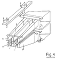
- This large free space for outflow of the air blown onto the glass pane 7 for cooling is also shown in the perspective illustration according to FIG. 4, in which the corresponding flow arrows are entered.
- the upper nozzle hearth 19o or its nozzle ribs 3b are pivotally mounted on a frame 11 about an axis of rotation 10.
- the height of the frame 11 can be finely adjusted by means of lifting elements 12 which are fastened to a stationary frame and are actuated by spindles, which are indicated in FIG. 3 by the rotating arrows, by means of an electric motor 13.
- the entire upper nozzle range 3 can be swiveled out rapidly about the axis of rotation 10 by means of a compressed air cylinder 14.
- This double-acting compressed air cylinder 14 causes this pivoting movement during normal operation of the nozzle hearth.
- a special locking mechanism can also be provided, which is triggered by the lifting movement of the compressed air cylinder 14. Such locking is particularly useful when the nozzle section must be operated at high pressures.
- the lower nozzle hearth 19u or nozzle ribs 2a is pivoted away by means of a compressed air cylinder 17 about a swivel joint 15 possible, which is also designed to be adjustable in height, as indicated by the double arrow in FIG. 3.
- a swivel joint 15 which is also designed to be adjustable in height, as indicated by the double arrow in FIG. 3.
- only a fine adjustment of the height by means of a stop 16 and the height-adjustable swivel joint 15 is necessary, since the distance of the lower nozzles from the underside of the glass pane 7 depends only on the position of the lower nozzle ribs 2a with respect to the rollers 1 and for all glass thicknesses is equal to.
- the route shown in FIG. 3 is suitable for automation if appropriate computer-controlled motors and displacement sensors are installed.
- the distance 5.6 of the upper nozzle field 19o and the lower nozzle field 19u from the roller hearth surface can be set in the manner described depending on the respective operating condition requirements. As a rule, it can be assumed that the distance of the upper nozzle ribs 3b from the top of the glass pane 7 should be approximately twice as large as the distance of the lower nozzle ribs 2a from the underside of the glass pane.
- thermally toughened single-pane safety glass is, in addition to the satisfactory appearance, guaranteed by good flatness and a damage-free surface, also the achievement of a fracture pattern that complies with the relevant regulations and, on the one hand, from the height of the rugged ones Cooling process achieved prestress and on the other hand depends on the distribution of this prestress, since the spread of fracture lines is based on the stress distribution in the glass, see German Patent No. 28 27 754, according to which the formation of splinters can be influenced favorably by appropriate gradation of the stress.
- Such an influence on the voltage is possible, for example, by changing the cooling, as has been practiced for a long time for coarse crumb fields of view of windshields made from single-pane safety glass for passenger cars through a coarser nozzle field.
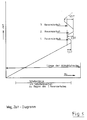
- the disc length and thus the position of the front edge of the disc at the beginning of the first reversing stroke are indicated under the X axis.
- the disk 7 is first moved very quickly into the cooling section until its front edge has reached the indicated position.
- the disc is held in this position for a short time before the first reversing stroke begins, in which the disc is pushed back a little against the original direction of movement.
- This reversing stroke is a multiple of the nozzle pitch T, whereby the prestress in the glass changes in accordance with the nozzle or roller pitch T.
- the glass pane then remains in this position for a short time before the second reversing stroke begins in the opposite direction, namely over the distance 2.5 T.
- the pane then remains in this new position for a short time before the third reversing stroke with the length 3.5 T against the entry direction begins. If necessary, further reversing strokes can follow this.
- the length of the skewers can be shortened in that the strip-like cooling which is produced during reversing is refined by reversing with strokes of an odd multiple of half the division. This can also be combined with the change in the size of the reversing path from stroke to stroke shown in FIG. 5.
- the heat transfer for. B. reduced by reducing the nozzle area, in the direction of passage of the pretensioning section or reduced in total synchronously with the running-in of the disc, the nozzle pressure.
- This reduction in nozzle pressure can be achieved, for example, by reducing the speed of the fan (s) supplying the nozzle fields (not shown).
- the flow can be individually throttled when entering the nozzle ribs, thereby reducing the nozzle pressure.
- the gas pressure in both the upper and lower nozzle ribs of the two nozzle fields can be reduced in the direction of passage of the glass pane from nozzle rib to nozzle rib.
Landscapes
- Chemical & Material Sciences (AREA)
- Engineering & Computer Science (AREA)
- Materials Engineering (AREA)
- Organic Chemistry (AREA)
- Physics & Mathematics (AREA)
- Thermal Sciences (AREA)
- Re-Forming, After-Treatment, Cutting And Transporting Of Glass Products (AREA)
- Advancing Webs (AREA)
- Chemical Vapour Deposition (AREA)
- Rollers For Roller Conveyors For Transfer (AREA)
- Coating With Molten Metal (AREA)
- Tunnel Furnaces (AREA)
Claims (23)
- Parcours à tuyères de projection de gaz sous forte convection pour un produit plat transporté sur des rouleaux, en particulier pour la précontrainte thermique de vitres minces et plates,a) comportant un champ inférieur de tuyère (2) avec des rampes de tuyères (2a) dotées d'ouvertures de tuyères et disposées parallèlement et centralement entre les rouleaux (1), etb) avec un champ supérieur de tuyères (3) dont les rampes de tuyères (3b) dotées d'ouvertures de tuyères sont disposées symétriquement par rapport à l'axe vertical d'une rampe inférieure de tuyères (2a) associées et opposées,c) tandis que les jets de gaz sortant de certaines ouvertures de tuyères viennent frapper perpendiculairement la surface du produit, les jets de gaz sortant d'autres ouvertures de tuyères venant frapper cette surface obliquement,caractérisé par les caractéristiques suivantes:d) les fonds à tuyères (4) des rampes supérieures de tuyères (3a) présentent une section transversale en forme de lettre "M" élargie par une bande médiane (4a);e) la largeur du fond à tuyères (4) des rampes supérieures de tuyères (3b) est plus grande que l'écart horizontal entre les rouleaux (1) et est plus petite que l'entr'axe (T) des rouleaux;f) la bande médiane (4a) ainsi que les deux ailes intérieures repliées vers le haut (4b₁, 4b₂) du fond à tuyères (4) des rampes supérieures de tuyères (3b) sont dotées d'ouvertures de tuyères (4d, 4e, 4f); etg) le plus petit écart (5) entre les rampes supérieures de tuyères (3b) et la face supérieure du produit (7) est plus grand que la plus petite distance (6) entre les rampes inférieures de tuyères (2a) et la face inférieure du produit (7).
- Parcours à tuyères de projection de gaz sous forte convection selon la revendication 1, caractérisé par les plages de dimensions ci-dessous pour les fonds à tuyères (4) des rampes supérieures de tuyères (3b):- pour une largeur totale BU des rampes inférieures de tuyères (2a), la largeur BP de la bande médiane (4a) essentiellement plane est située dans la plage suivante:
 - l'angle de pliage des deux ailes intérieures (4b₁, 4b₂) du fond à tuyères (4) vaut entre 5° et 10°;- la largeur BK des deux ailes intérieures repliées (4b₁, 4b₂) du fond supérieur à tuyères (4) par rapport à la largeur totale BU des rampes inférieures de tuyères (2a) est située dans la plage suivante:
 - l'inclinaison des deux ailes extérieures (4c) repliées vers le bas des fonds supérieurs à tuyères (4) par rapport à l'horizontale est située dans la plage de 40° à 50°, et vaut en particulier environ 45°; et- par rapport à la largeur totale Bu des rampes inférieures de tuyères (2a), la largeur BR des deux ailes extérieures (4c), repliées vers le bas, des fonds supérieurs à tuyères (4) est située dans la plage suivante:
- Parcours à tuyères de projection de gaz sous forte convection selon l'une des revendications 1 ou 2, caractérisé en ce que la bande médiane plane (4a) des fonds supérieurs à tuyères (4) présente un nombre impair de rangées d'ouvertures de tuyères (4f) à un entr'axe des trous relativement plus petit et un diamètre relativement plus petit, en ce que les rangées de ces ouvertures de tuyères (4f) présentent l'une par rapport à l'autre une distance valant sensiblement un entr'axe des trous et sont chacune décalées l'une par rapport à l'autre dans la direction longitudinale d'un demi entr'axe des trous, en ce que les ailes intérieures repliées vers le haut (4b₁, 4b₂) des fonds supérieurs à tuyères (4) présentent d'autres rangées d'ouvertures de tuyères (4d, 4e) d'un plus grand diamètre d'ouverture et d'un plus grand entr'axe des trous, et en ce que le diamètre et/ou l'entr'axe des trous des ouvertures de tuyères (4d, 4e, 4f) augmentent de l'intérieur vers l'extérieur dans l'ordre des rangées d'ouvertures de tuyères (4d, 4e, 4f).
- Parcours à tuyères de projection de gaz sous forte convection selon l'une des revendications 1 à 3, caractérisé en ce que les fonds de tuyères (4) des rampes supérieures de tuyères (3b) présentent dans la bande médiane (4a) trois rangées d'ouvertures de tuyères (4f), et en ce que les deux ailes repliées vers le haut (4b₁, 4b₂) qui s'y raccordent présentent chacune deux rangées d'ouvertures de tuyères (4d, 4e) avec un entr'axe des trous double.
- Parcours à tuyères de projection de gaz sous forte convection selon au moins l'une des revendications 1 à 4, caractérisé en ce que, par la sélection de leur position, de leur diamètre et de l'angle d'inclinaison des jets de tuyères émis par elles, les ouvertures de tuyères des rampes supérieures et des rampes inférieures de tuyères (2a, 3b) créent un motif d'attaque sur une face d'un produit qui est l'image spéculaire du motif d'attaque sur la face opposée du produit.
- Parcours à tuyères de projection de gaz sous forte convection selon l'une des revendications 1 à 5, caractérisé en ce que la surface géométrique de sortie des tuyères vaut environ 2% à environ 5% de la surface balayée d'un côté du produit (7), et en ce que la surface de sortie des tuyères est identique pour les rampes supérieures et les rampes inférieures de tuyères (2a, 3b).
- Parcours à tuyères de projection de gaz sous forte convection selon l'une des revendications 1 à 6, caractérisé en ce qu'en pourcentage, la surface des ouvertures de tuyères diminue dans la direction de la traversée du parcours à tuyères.
- Parcours à tuyères de projection de gaz sous forte convection selon au moins l'une des revendications 1 à 7, caractérisé en ce que l'entr'axe des rouleaux (1) et rampes de tuyères (2a, 3b) est situé dans la plage d'environ 60 mm à environ 150 mm.
- Parcours à tuyères de projection de gaz sous forte convection selon l'une des revendications 1 à 8, caractérisé en ce que les rampes inférieures de tuyères (2a) sont repliées en coupe à la manière d'un toit en croupe, et en ce que tant les surfaces inclinées vers le bas (2a₂) que les surfaces horizontales (2a₁) présentent des ouvertures de tuyères (2b, 2c, 2d).
- Parcours à tuyères de projection de gaz sous forte convection selon l'une des revendications 1 à 9, caractérisé en ce que la distance (5) entre le champ supérieur de tuyères (3) et la surface du champ de rouleaux, ainsi que la distance (6) entre le champ inférieur de tuyères (2) et la surface du champ de rouleaux, sont ajustables.
- Parcours à tuyères de projection de gaz sous forte convection selon l'une des revendications 1 à 10, caractérisé en ce que la distance (5) entre le champ supérieur de tuyères (3) et le produit (7) vaut sensiblement le double de la distance (6) entre le champ inférieur de tuyères (2) et le produit (7).
- Parcours à tuyères de projection de gaz sous forte convection selon au moins l'une des revendications 1 à 11, caractérisé en ce que la pression de tuyères est approximativement identique pour le champ supérieur de tuyères (3) et le champ inférieur de tuyères (2).
- Parcours à tuyères de projection de gaz sous forte convection selon l'une au moins des revendications 1 à 12, caractérisé en ce que lors de l'utilisation de ce parcours à tuyères pour la précontrainte thermique de vitre (7), la pression de tuyères est réduite lors de l'introduction de la vitre ou après celle-ci.
- Parcours à tuyères de projection de gaz sous forte convection selon la revendication 13, caractérisé en ce que la pression de tuyères est réduite par réduction de la vitesse de rotation du ou des ventilateurs alimentant les champs de tuyères (2, 3).
- Parcours à tuyères de projection de gaz sous forte convection selon l'une au moins des revendications 1 à 14, caractérisé en ce que la pression de gaz diminue d'une rampe de tuyères à l'autre dans la direction de traversée du produit plat, tant dans les rampes supérieures de tuyères (3b) que dans les rampes inférieures de tuyères (2a).
- Parcours à tuyères de projection de gaz sous forte convection selon la revendication 15, caractérisé en ce que l'écoulement est étranglé individuellement à l'entrée dans les rampes de tuyères (2a, 3b).
- Parcours à tuyères de projection de gaz sous forte convection selon l'une au moins des revendications 1 à 16, caractérisé en ce que lorsque le parcours à tuyères est utilisé pour la précontrainte thermique des vitres (7), chaque vitre (7) est arrêtée après sa pénétration dans le parcours de refroidissement, et elle est ensuite au moins une fois déplacée en va-et-vient sur une course qui représente un multiple de la moitié de l'entr'axe (T) des rouleaux.
- Parcours à tuyères de projection de gaz sous forte convection selon la revendication 17, caractérisé en ce que la course du va-et-vient est différente dans au moins un déplacement en va-et-vient.
- Parcours à tuyères de projection de gaz sous forte convection selon l'une des revendications 1 à 18, pour la précontrainte de vitres minces, caractérisé en ce que les rampes supérieures de tuyères (3b) sont montées sur un châssis (11) à pivotement commun autour d'un point de rotation (10) qui peut être ajusté verticalement au moyen des tiges filetées de déplacement (12) et d'un entraînement (13) des tiges filetées de déplacement, en ce que l'ensemble du champ supérieur de tuyères (3) peut être pivoté vers le haut autour du point de rotation (10) au moyen d'un cylindre pneumatique (14), en ce que le champ inférieur des tuyères (2) peut être pivoté au moyen d'un cylindre pneumatique (17) autour d'un point de rotation (15) ajustable en hauteur, et peut être repoussé au moyen du même cylindre (17) contre une butée (16) ajustable en hauteur.
- Parcours à tuyères de projection de gaz sous forte convection selon la revendication 18, caractérisé en ce que sont prévus des enregistreurs de déplacement pour la détection du parcours ajustable en hauteur, et en ce que l'ajustement en hauteur s'effectue par des moteurs et par l'intermédiaire d'une régulation commandée par calculateur.
- Parcours à tuyères de projection de gaz sous forte convection selon l'une des revendications 1 à 20, pour la précontrainte de vitres, caractérisé en ce que les rouleaux (1) pour le transport des vitres (7) sont dotés sur la totalité de leur périphérie de supports de vitres (7) qui ne constituent globalement que la plus petite partie de la surface d'enveloppe de chaque rouleau.
- Parcours à tuyères de projection de gaz sous forte convection selon la revendication 21, caractérisé en ce que les supports sont constitués par des anneaux toriques en caoutchouc fluoré.
- Parcours à tuyères de projection de gaz sous forte convection selon la revendication 21, caractérisé en ce que les supports sont constitués d'un matériau en fibres de silicate, en particulier d'un matériau en fibres de silicate de calcium, en association avec des liants appropriés.
Applications Claiming Priority (2)
| Application Number | Priority Date | Filing Date | Title |
|---|---|---|---|
| DE4002546A DE4002546C2 (de) | 1990-01-29 | 1990-01-29 | Hochkonvektions-Gasstrahldüsenstrecke für über Rollen geführtes, flächenhaftes Gut, sowie Verfahren zu deren Betrieb |
| DE4002546 | 1990-01-29 |
Publications (3)
| Publication Number | Publication Date |
|---|---|
| EP0440113A2 EP0440113A2 (fr) | 1991-08-07 |
| EP0440113A3 EP0440113A3 (en) | 1992-07-15 |
| EP0440113B1 true EP0440113B1 (fr) | 1995-09-27 |
Family
ID=6398985
Family Applications (1)
| Application Number | Title | Priority Date | Filing Date |
|---|---|---|---|
| EP91100999A Expired - Lifetime EP0440113B1 (fr) | 1990-01-29 | 1991-01-25 | Chemin de tuyères à gaz à forte convection pour matériaux plats transportés sur des rouleaux |
Country Status (5)
| Country | Link |
|---|---|
| US (1) | US5094678A (fr) |
| EP (1) | EP0440113B1 (fr) |
| AT (1) | ATE128442T1 (fr) |
| DE (2) | DE4002546C2 (fr) |
| ES (1) | ES2078359T3 (fr) |
Families Citing this family (30)
| Publication number | Priority date | Publication date | Assignee | Title |
|---|---|---|---|---|
| FI91248C (fi) * | 1992-09-23 | 1994-06-10 | Aulis Bertin | Lasin lämpökäsittelymenetelmä |
| DE4402606C2 (de) * | 1994-01-28 | 1996-09-05 | Kramer Carl | Hochkonvektions-Gasstrahldüsenstrecke zum thermischen Vorspannen flächenhaften Gutes, insbesondere Glasscheiben |
| US5672191A (en) * | 1994-06-20 | 1997-09-30 | Gas Research Institute | Forced convection heating apparatus and process for heating glass sheets therewithin |
| US5746799A (en) * | 1994-06-20 | 1998-05-05 | Gas Research Institute | Process for heating glass sheets within a forced convection heating apparatus by mixing and distributing spent working fluid and combustion gases |
| US5669954A (en) * | 1994-06-20 | 1997-09-23 | Gas Research Institute | Forced convection heating apparatus and process for heating glass sheets therewithin |
| DE19544995C1 (de) | 1995-12-02 | 1997-04-03 | Kramer Carl | Horizontale Vorspannstrecke mit großer Arbeitsbreite für Flachglas |
| US6045358A (en) * | 1996-01-19 | 2000-04-04 | Glasstech, Inc. | Forced convection heating apparatus and process for heating glass sheets therewithin |
| DE29603022U1 (de) * | 1996-02-21 | 1996-04-18 | Ipsen Industries International GmbH, 47533 Kleve | Vorrichtung zum Abschrecken metallischer Werkstücke |
| US6295842B1 (en) | 1998-10-21 | 2001-10-02 | Glasstech, Inc. | Uniform distribution quenching of formed glass sheets |
| US6050814A (en) * | 1998-12-09 | 2000-04-18 | Glasstech, Inc. | Forced convection furnace for heating glass sheets |
| US20050098622A1 (en) * | 2001-10-09 | 2005-05-12 | Gregory Jantsch | Dispensing of currency |
| US7387236B2 (en) * | 2001-10-09 | 2008-06-17 | Delaware Capital Formation, Inc. | Dispensing of currency |
| ITMI20021506A1 (it) * | 2002-07-10 | 2004-01-12 | Danieli Off Mecc | Dispositivo di regolazione della temperatura del nastro in un impianto di colata continua di nastro metallico |
| DE602004027235D1 (de) * | 2003-03-31 | 2010-07-01 | Glassrobots Oy | Umluftheizofen für eine vorgespannte glasscheibe |
| US20060150683A1 (en) * | 2005-01-11 | 2006-07-13 | Glasstech, Inc. | Apparatus and method for glass sheet quenching |
| US20070001383A1 (en) * | 2005-06-20 | 2007-01-04 | Gregory Jantsch | Dispensing of currency |
| US20090173106A1 (en) * | 2008-01-04 | 2009-07-09 | Boisselle Robert J | Glass tempering method and apparatus |
| FI124601B (fi) * | 2010-09-22 | 2014-10-31 | Glaston Services Ltd Oy | Suutinkotelorakenne |
| CN102757173B (zh) * | 2012-06-22 | 2014-11-12 | 杭州精工机械有限公司 | 超薄钢化玻璃生产线及生产方法 |
| BE1024010B1 (fr) * | 2012-09-21 | 2017-10-27 | Agc Glass Europe | Bombage de vitrages |
| WO2014111622A1 (fr) * | 2013-01-18 | 2014-07-24 | Feracitas Oy | Procédé pour améliorer une circulation d'air et moyen pour chauffer de l'air dans un four de trempage de verre |
| US9423177B2 (en) * | 2013-02-22 | 2016-08-23 | Ricoh Company, Ltd. | Force-balancing gas flow in dryers for printing systems |
| US9573833B2 (en) * | 2014-03-31 | 2017-02-21 | Corning Incorporated | Method and lift jet floatation system for shaping thin glass |
| CN103951176B (zh) * | 2014-04-11 | 2016-06-15 | 洛阳兰迪玻璃机器股份有限公司 | 一种快速加热玻璃板的加热炉 |
| DE202016006191U1 (de) | 2016-09-28 | 2018-01-02 | FASA GmbH Gesellschaft für Management, Innovation und Consulting | Schwibbogen nach Art des Erzgebirgischen Kunsthandwerks |
| CN107661829A (zh) * | 2017-09-30 | 2018-02-06 | 江苏云端重工科技有限公司 | 一种沥青回收专用清洗喷头 |
| DE202017006469U1 (de) | 2017-12-16 | 2018-03-15 | Thomas Achatz | Schwibbogen nach Art der Erzgebirgischen Volkskunst |
| US20220169552A1 (en) * | 2020-12-01 | 2022-06-02 | Tung Chang Machinery And Engineering Co., Ltd. | Wind outlet structure and cooling device |
| DE202021002276U1 (de) | 2021-06-21 | 2021-07-12 | Kleinkunst aus dem Erzgebirge Müller GmbH | Lichterspitze nach Art der Erzgebirgischen Volkskunst |
| CN116924667B (zh) * | 2022-03-29 | 2025-07-01 | 洛阳兰迪玻璃机器股份有限公司 | 一种玻璃钢化冷却工艺中减弱玻璃风斑的方法 |
Family Cites Families (16)
| Publication number | Priority date | Publication date | Assignee | Title |
|---|---|---|---|---|
| US3353946A (en) * | 1964-01-29 | 1967-11-21 | Permaglass | Blasthead structure for tempering glass sheets |
| US3404974A (en) * | 1965-04-21 | 1968-10-08 | Corning Glass Works | Cooling arrangement for glass forming equipment |
| US3595636A (en) * | 1968-05-03 | 1971-07-27 | Ppg Industries Inc | Apparatus for shaping and cooling glass sheets |
| DE2256087C3 (de) * | 1972-11-16 | 1982-06-24 | Vits-Maschinenbau Gmbh, 4018 Langenfeld | Vorrichtung zum Trocknen einer auf einem im wesentlichen eben geführten Träger aufliegenden Warenbahn |
| US3875766A (en) * | 1973-12-20 | 1975-04-08 | Fifth Res | Method for the direct manufacture of discrete tempered glass sheets |
| AT359229B (de) * | 1975-03-07 | 1980-10-27 | Siemens Ag Oesterreich | Transportvorrichtung fuer auf erweichungs- temperatur erhitzte glastafeln |
| IE47093B1 (en) * | 1977-06-23 | 1983-12-14 | Triplex Safety Glass Co | Improvements in or relating to toughened glass sheets and method for their production |
| DE2827757A1 (de) * | 1978-06-24 | 1980-01-10 | Johannes Heyen | Tunnelabdichtung mit selbstklebender dichtungsbahn |
| GB2064507B (en) * | 1979-11-21 | 1983-06-02 | Bfg Glassgroup | Removing broken fragments formed during glass treatment eg tempering |
| US4323385A (en) * | 1980-07-21 | 1982-04-06 | Ppg Industries, Inc. | Nozzle arrangement for glass sheet tempering apparatus |
| US4363163A (en) * | 1980-11-13 | 1982-12-14 | Mcmaster Harold | Quench roll including helically wrapped support |
| DE3150859C1 (de) * | 1981-12-22 | 1983-03-10 | Karl-Heinz Dipl.-Ing. 5107 Lammersdorf Dicks | Vorrichtung zum Wölben von Glasscheiben |
| EP0114168B1 (fr) * | 1983-01-21 | 1987-07-29 | Karl-Heinz Dipl.-Ing. Dicks | Appareil de bombage de plaques en verre |
| FR2547575B1 (fr) * | 1983-06-14 | 1985-10-04 | Saint Gobain Vitrage | Perfectionnement a la trempe du verre |
| FI76314C (fi) * | 1986-10-29 | 1988-10-10 | Kyro Oy | Stroemningshinder i kylavdelningen till en glashaerdningsanlaeggning. |
| FI76315C (fi) * | 1986-10-29 | 1988-10-10 | Kyro Oy | Anordning i kylavdelningen till en glashaerdningsanlaeggning. |
-
1990
- 1990-01-29 DE DE4002546A patent/DE4002546C2/de not_active Expired - Lifetime
-
1991
- 1991-01-25 DE DE59106563T patent/DE59106563D1/de not_active Expired - Fee Related
- 1991-01-25 ES ES91100999T patent/ES2078359T3/es not_active Expired - Lifetime
- 1991-01-25 EP EP91100999A patent/EP0440113B1/fr not_active Expired - Lifetime
- 1991-01-25 AT AT91100999T patent/ATE128442T1/de not_active IP Right Cessation
- 1991-01-28 US US07/646,035 patent/US5094678A/en not_active Expired - Lifetime
Also Published As
| Publication number | Publication date |
|---|---|
| EP0440113A3 (en) | 1992-07-15 |
| ATE128442T1 (de) | 1995-10-15 |
| US5094678A (en) | 1992-03-10 |
| ES2078359T3 (es) | 1995-12-16 |
| DE4002546A1 (de) | 1991-08-01 |
| DE59106563D1 (de) | 1995-11-02 |
| DE4002546C2 (de) | 1994-07-14 |
| EP0440113A2 (fr) | 1991-08-07 |
Similar Documents
| Publication | Publication Date | Title |
|---|---|---|
| EP0440113A2 (fr) | Chemin de tuyères à gaz à forte convection pour matériaux plats transportés sur des rouleaux | |
| EP0541630B1 (fr) | Dispositif de refroidissement de profiles extrudes | |
| EP0649821A1 (fr) | Dispositif pour l'échauffement ou le refroidissement de feuilles ou de rubans de verre | |
| DE69833871T2 (de) | Vorrichtung zur härtung gebogenen glasscheiben | |
| DE19649073C2 (de) | Vorrichtung zur Abkühlung von Strangpreßprofilen | |
| DE1811435A1 (de) | Verfahren und Vorrichtung zum Vorspannen von Glasscheiben | |
| DE69524118T2 (de) | Verfahren und vorrichtung zum justieren der abschreckeinrichtung einer vorrichtung zum vorspannen von gebogenen glasplatten | |
| EP0114168B1 (fr) | Appareil de bombage de plaques en verre | |
| DE2163268C3 (de) | Ofen zum Erwärmen von Glasplatten | |
| AT406046B (de) | Vorrichtung zum transportieren und kühlen von glasscheiben | |
| EP3818020B1 (fr) | Dispositif destiné à tempérer des plaques de verre | |
| EP3655367A1 (fr) | Caisson de soufflage pour la trempe thermique de vitres | |
| EP3487817B1 (fr) | Rampe de buses pour caisson de soufflage destiné à la trempe thermique de feuilles de verre | |
| DE2256087B2 (de) | Vorrichtung zum Trocknen einer auf einem im wesentlichen eben geführten Träger aufliegenden Warenbahn | |
| DE2118589A1 (de) | Verfahren und Vorrichtung zum fortlaufenden Umlenken eines Glasbandes in plastischem Zustand | |
| DE3150859C1 (de) | Vorrichtung zum Wölben von Glasscheiben | |
| EP0425998B1 (fr) | Barrière pour empêcher des coups en arrière | |
| DE2840834B2 (de) | Vorrichtung zum Vorspannen der obenliegenden der beiden gleichzeitig gebogenen Einzelscheiben einer Verbundsicherheitsscheibe im Biegeofen | |
| DE4402606C2 (de) | Hochkonvektions-Gasstrahldüsenstrecke zum thermischen Vorspannen flächenhaften Gutes, insbesondere Glasscheiben | |
| DE19642876C1 (de) | Biegevorrichtung für auf Erweichungstemperatur erwärmte Glasscheiben | |
| DE2462154C3 (de) | Vorrichtung zum thermischen Vorspannen von Glasscheiben | |
| DE1596632B1 (de) | Verfahren und Vorrichtung zur Haertung von Tafelglas | |
| DE2447411B2 (de) | Vorrichtung zum Vorspannen großer Glasscheiben | |
| DE1596384B2 (de) | Verfahren zum transport einer im weichen zustand sich befindenden glasscheibe und vorrichtung zur durchfuehrung des verfahrens | |
| DE2462155C3 (de) | Vorrichtung zum thermischen Vorspannen von Glasscheiben |
Legal Events
| Date | Code | Title | Description |
|---|---|---|---|
| PUAI | Public reference made under article 153(3) epc to a published international application that has entered the european phase |
Free format text: ORIGINAL CODE: 0009012 |
|
| AK | Designated contracting states |
Kind code of ref document: A2 Designated state(s): AT BE CH DE ES FR GB IT LI NL |
|
| PUAL | Search report despatched |
Free format text: ORIGINAL CODE: 0009013 |
|
| AK | Designated contracting states |
Kind code of ref document: A3 Designated state(s): AT BE CH DE ES FR GB IT LI NL |
|
| 17P | Request for examination filed |
Effective date: 19921229 |
|
| 17Q | First examination report despatched |
Effective date: 19941017 |
|
| GRAA | (expected) grant |
Free format text: ORIGINAL CODE: 0009210 |
|
| ITF | It: translation for a ep patent filed | ||
| AK | Designated contracting states |
Kind code of ref document: B1 Designated state(s): AT BE CH DE ES FR GB IT LI NL |
|
| REF | Corresponds to: |
Ref document number: 128442 Country of ref document: AT Date of ref document: 19951015 Kind code of ref document: T |
|
| GBT | Gb: translation of ep patent filed (gb section 77(6)(a)/1977) |
Effective date: 19950928 |
|
| REF | Corresponds to: |
Ref document number: 59106563 Country of ref document: DE Date of ref document: 19951102 |
|
| REG | Reference to a national code |
Ref country code: ES Ref legal event code: FG2A Ref document number: 2078359 Country of ref document: ES Kind code of ref document: T3 |
|
| ET | Fr: translation filed | ||
| PLBE | No opposition filed within time limit |
Free format text: ORIGINAL CODE: 0009261 |
|
| STAA | Information on the status of an ep patent application or granted ep patent |
Free format text: STATUS: NO OPPOSITION FILED WITHIN TIME LIMIT |
|
| 26N | No opposition filed | ||
| REG | Reference to a national code |
Ref country code: GB Ref legal event code: IF02 |
|
| PGFP | Annual fee paid to national office [announced via postgrant information from national office to epo] |
Ref country code: DE Payment date: 20050119 Year of fee payment: 15 |
|
| PGFP | Annual fee paid to national office [announced via postgrant information from national office to epo] |
Ref country code: GB Payment date: 20050120 Year of fee payment: 15 |
|
| PGFP | Annual fee paid to national office [announced via postgrant information from national office to epo] |
Ref country code: NL Payment date: 20050121 Year of fee payment: 15 Ref country code: CH Payment date: 20050121 Year of fee payment: 15 Ref country code: AT Payment date: 20050121 Year of fee payment: 15 |
|
| PGFP | Annual fee paid to national office [announced via postgrant information from national office to epo] |
Ref country code: FR Payment date: 20050124 Year of fee payment: 15 |
|
| PGFP | Annual fee paid to national office [announced via postgrant information from national office to epo] |
Ref country code: ES Payment date: 20050128 Year of fee payment: 15 |
|
| PGFP | Annual fee paid to national office [announced via postgrant information from national office to epo] |
Ref country code: BE Payment date: 20050302 Year of fee payment: 15 |
|
| PG25 | Lapsed in a contracting state [announced via postgrant information from national office to epo] |
Ref country code: GB Free format text: LAPSE BECAUSE OF NON-PAYMENT OF DUE FEES Effective date: 20060125 Ref country code: AT Free format text: LAPSE BECAUSE OF NON-PAYMENT OF DUE FEES Effective date: 20060125 |
|
| PG25 | Lapsed in a contracting state [announced via postgrant information from national office to epo] |
Ref country code: ES Free format text: LAPSE BECAUSE OF NON-PAYMENT OF DUE FEES Effective date: 20060126 |
|
| PG25 | Lapsed in a contracting state [announced via postgrant information from national office to epo] |
Ref country code: LI Free format text: LAPSE BECAUSE OF NON-PAYMENT OF DUE FEES Effective date: 20060131 Ref country code: FR Free format text: LAPSE BECAUSE OF NON-PAYMENT OF DUE FEES Effective date: 20060131 Ref country code: CH Free format text: LAPSE BECAUSE OF NON-PAYMENT OF DUE FEES Effective date: 20060131 Ref country code: BE Free format text: LAPSE BECAUSE OF NON-PAYMENT OF DUE FEES Effective date: 20060131 |
|
| PGFP | Annual fee paid to national office [announced via postgrant information from national office to epo] |
Ref country code: IT Payment date: 20060131 Year of fee payment: 16 |
|
| PG25 | Lapsed in a contracting state [announced via postgrant information from national office to epo] |
Ref country code: NL Free format text: LAPSE BECAUSE OF NON-PAYMENT OF DUE FEES Effective date: 20060801 Ref country code: DE Free format text: LAPSE BECAUSE OF NON-PAYMENT OF DUE FEES Effective date: 20060801 |
|
| REG | Reference to a national code |
Ref country code: CH Ref legal event code: PL |
|
| GBPC | Gb: european patent ceased through non-payment of renewal fee |
Effective date: 20060125 |
|
| NLV4 | Nl: lapsed or anulled due to non-payment of the annual fee |
Effective date: 20060801 |
|
| REG | Reference to a national code |
Ref country code: FR Ref legal event code: ST Effective date: 20060929 |
|
| REG | Reference to a national code |
Ref country code: ES Ref legal event code: FD2A Effective date: 20060126 |
|
| BERE | Be: lapsed |
Owner name: INGENIEURGESELLSCHAFT FUR WARMETECHNIK STROMUNGSTE Effective date: 20060131 |
|
| PG25 | Lapsed in a contracting state [announced via postgrant information from national office to epo] |
Ref country code: IT Free format text: LAPSE BECAUSE OF NON-PAYMENT OF DUE FEES Effective date: 20070125 |