EP0542002A2 - Catalyseur pour gaz d'échappement d'un moteur à combustion interne - Google Patents
Catalyseur pour gaz d'échappement d'un moteur à combustion interne Download PDFInfo
- Publication number
- EP0542002A2 EP0542002A2 EP92117984A EP92117984A EP0542002A2 EP 0542002 A2 EP0542002 A2 EP 0542002A2 EP 92117984 A EP92117984 A EP 92117984A EP 92117984 A EP92117984 A EP 92117984A EP 0542002 A2 EP0542002 A2 EP 0542002A2
- Authority
- EP
- European Patent Office
- Prior art keywords
- arrangement according
- fibers
- catalyst body
- metal
- mixture
- Prior art date
- Legal status (The legal status is an assumption and is not a legal conclusion. Google has not performed a legal analysis and makes no representation as to the accuracy of the status listed.)
- Granted
Links
Images
Classifications
-
- B—PERFORMING OPERATIONS; TRANSPORTING
- B01—PHYSICAL OR CHEMICAL PROCESSES OR APPARATUS IN GENERAL
- B01D—SEPARATION
- B01D53/00—Separation of gases or vapours; Recovering vapours of volatile solvents from gases; Chemical or biological purification of waste gases, e.g. engine exhaust gases, smoke, fumes, flue gases, aerosols
- B01D53/34—Chemical or biological purification of waste gases
- B01D53/92—Chemical or biological purification of waste gases of engine exhaust gases
- B01D53/94—Chemical or biological purification of waste gases of engine exhaust gases by catalytic processes
- B01D53/9445—Simultaneously removing carbon monoxide, hydrocarbons or nitrogen oxides making use of three-way catalysts [TWC] or four-way-catalysts [FWC]
- B01D53/945—Simultaneously removing carbon monoxide, hydrocarbons or nitrogen oxides making use of three-way catalysts [TWC] or four-way-catalysts [FWC] characterised by a specific catalyst
-
- B—PERFORMING OPERATIONS; TRANSPORTING
- B01—PHYSICAL OR CHEMICAL PROCESSES OR APPARATUS IN GENERAL
- B01D—SEPARATION
- B01D53/00—Separation of gases or vapours; Recovering vapours of volatile solvents from gases; Chemical or biological purification of waste gases, e.g. engine exhaust gases, smoke, fumes, flue gases, aerosols
- B01D53/34—Chemical or biological purification of waste gases
- B01D53/92—Chemical or biological purification of waste gases of engine exhaust gases
- B01D53/94—Chemical or biological purification of waste gases of engine exhaust gases by catalytic processes
- B01D53/9445—Simultaneously removing carbon monoxide, hydrocarbons or nitrogen oxides making use of three-way catalysts [TWC] or four-way-catalysts [FWC]
- B01D53/9454—Simultaneously removing carbon monoxide, hydrocarbons or nitrogen oxides making use of three-way catalysts [TWC] or four-way-catalysts [FWC] characterised by a specific device
-
- B—PERFORMING OPERATIONS; TRANSPORTING
- B01—PHYSICAL OR CHEMICAL PROCESSES OR APPARATUS IN GENERAL
- B01J—CHEMICAL OR PHYSICAL PROCESSES, e.g. CATALYSIS OR COLLOID CHEMISTRY; THEIR RELEVANT APPARATUS
- B01J35/00—Catalysts, in general, characterised by their form or physical properties
- B01J35/50—Catalysts, in general, characterised by their form or physical properties characterised by their shape or configuration
- B01J35/56—Foraminous structures having flow-through passages or channels, e.g. grids or three-dimensional [3D] monoliths
-
- B—PERFORMING OPERATIONS; TRANSPORTING
- B01—PHYSICAL OR CHEMICAL PROCESSES OR APPARATUS IN GENERAL
- B01J—CHEMICAL OR PHYSICAL PROCESSES, e.g. CATALYSIS OR COLLOID CHEMISTRY; THEIR RELEVANT APPARATUS
- B01J35/00—Catalysts, in general, characterised by their form or physical properties
- B01J35/50—Catalysts, in general, characterised by their form or physical properties characterised by their shape or configuration
- B01J35/58—Fabrics or filaments
-
- F—MECHANICAL ENGINEERING; LIGHTING; HEATING; WEAPONS; BLASTING
- F01—MACHINES OR ENGINES IN GENERAL; ENGINE PLANTS IN GENERAL; STEAM ENGINES
- F01N—GAS-FLOW SILENCERS OR EXHAUST APPARATUS FOR MACHINES OR ENGINES IN GENERAL; GAS-FLOW SILENCERS OR EXHAUST APPARATUS FOR INTERNAL-COMBUSTION ENGINES
- F01N3/00—Exhaust or silencing apparatus having means for purifying, rendering innocuous, or otherwise treating exhaust
- F01N3/08—Exhaust or silencing apparatus having means for purifying, rendering innocuous, or otherwise treating exhaust for rendering innocuous
- F01N3/10—Exhaust or silencing apparatus having means for purifying, rendering innocuous, or otherwise treating exhaust for rendering innocuous by thermal or catalytic conversion of noxious components of exhaust
- F01N3/24—Exhaust or silencing apparatus having means for purifying, rendering innocuous, or otherwise treating exhaust for rendering innocuous by thermal or catalytic conversion of noxious components of exhaust characterised by constructional aspects of converting apparatus
- F01N3/28—Construction of catalytic reactors
- F01N3/2803—Construction of catalytic reactors characterised by structure, by material or by manufacturing of catalyst support
- F01N3/2807—Metal other than sintered metal
- F01N3/281—Metallic honeycomb monoliths made of stacked or rolled sheets, foils or plates
- F01N3/2814—Metallic honeycomb monoliths made of stacked or rolled sheets, foils or plates all sheets, plates or foils being corrugated
-
- F—MECHANICAL ENGINEERING; LIGHTING; HEATING; WEAPONS; BLASTING
- F01—MACHINES OR ENGINES IN GENERAL; ENGINE PLANTS IN GENERAL; STEAM ENGINES
- F01N—GAS-FLOW SILENCERS OR EXHAUST APPARATUS FOR MACHINES OR ENGINES IN GENERAL; GAS-FLOW SILENCERS OR EXHAUST APPARATUS FOR INTERNAL-COMBUSTION ENGINES
- F01N3/00—Exhaust or silencing apparatus having means for purifying, rendering innocuous, or otherwise treating exhaust
- F01N3/08—Exhaust or silencing apparatus having means for purifying, rendering innocuous, or otherwise treating exhaust for rendering innocuous
- F01N3/10—Exhaust or silencing apparatus having means for purifying, rendering innocuous, or otherwise treating exhaust for rendering innocuous by thermal or catalytic conversion of noxious components of exhaust
- F01N3/24—Exhaust or silencing apparatus having means for purifying, rendering innocuous, or otherwise treating exhaust for rendering innocuous by thermal or catalytic conversion of noxious components of exhaust characterised by constructional aspects of converting apparatus
- F01N3/28—Construction of catalytic reactors
- F01N3/2803—Construction of catalytic reactors characterised by structure, by material or by manufacturing of catalyst support
- F01N3/2807—Metal other than sintered metal
- F01N3/281—Metallic honeycomb monoliths made of stacked or rolled sheets, foils or plates
- F01N3/2817—Metallic honeycomb monoliths made of stacked or rolled sheets, foils or plates only with non-corrugated sheets, plates or foils
-
- F—MECHANICAL ENGINEERING; LIGHTING; HEATING; WEAPONS; BLASTING
- F01—MACHINES OR ENGINES IN GENERAL; ENGINE PLANTS IN GENERAL; STEAM ENGINES
- F01N—GAS-FLOW SILENCERS OR EXHAUST APPARATUS FOR MACHINES OR ENGINES IN GENERAL; GAS-FLOW SILENCERS OR EXHAUST APPARATUS FOR INTERNAL-COMBUSTION ENGINES
- F01N3/00—Exhaust or silencing apparatus having means for purifying, rendering innocuous, or otherwise treating exhaust
- F01N3/08—Exhaust or silencing apparatus having means for purifying, rendering innocuous, or otherwise treating exhaust for rendering innocuous
- F01N3/10—Exhaust or silencing apparatus having means for purifying, rendering innocuous, or otherwise treating exhaust for rendering innocuous by thermal or catalytic conversion of noxious components of exhaust
- F01N3/24—Exhaust or silencing apparatus having means for purifying, rendering innocuous, or otherwise treating exhaust for rendering innocuous by thermal or catalytic conversion of noxious components of exhaust characterised by constructional aspects of converting apparatus
- F01N3/28—Construction of catalytic reactors
- F01N3/2803—Construction of catalytic reactors characterised by structure, by material or by manufacturing of catalyst support
- F01N3/2835—Construction of catalytic reactors characterised by structure, by material or by manufacturing of catalyst support fibrous
-
- F—MECHANICAL ENGINEERING; LIGHTING; HEATING; WEAPONS; BLASTING
- F01—MACHINES OR ENGINES IN GENERAL; ENGINE PLANTS IN GENERAL; STEAM ENGINES
- F01N—GAS-FLOW SILENCERS OR EXHAUST APPARATUS FOR MACHINES OR ENGINES IN GENERAL; GAS-FLOW SILENCERS OR EXHAUST APPARATUS FOR INTERNAL-COMBUSTION ENGINES
- F01N3/00—Exhaust or silencing apparatus having means for purifying, rendering innocuous, or otherwise treating exhaust
- F01N3/08—Exhaust or silencing apparatus having means for purifying, rendering innocuous, or otherwise treating exhaust for rendering innocuous
- F01N3/10—Exhaust or silencing apparatus having means for purifying, rendering innocuous, or otherwise treating exhaust for rendering innocuous by thermal or catalytic conversion of noxious components of exhaust
- F01N3/24—Exhaust or silencing apparatus having means for purifying, rendering innocuous, or otherwise treating exhaust for rendering innocuous by thermal or catalytic conversion of noxious components of exhaust characterised by constructional aspects of converting apparatus
- F01N3/28—Construction of catalytic reactors
- F01N3/2839—Arrangements for mounting catalyst support in housing, e.g. with means for compensating thermal expansion or vibration
- F01N3/285—Arrangements for mounting catalyst support in housing, e.g. with means for compensating thermal expansion or vibration specially adapted for fibrous supports, e.g. held in place by screens
-
- F—MECHANICAL ENGINEERING; LIGHTING; HEATING; WEAPONS; BLASTING
- F02—COMBUSTION ENGINES; HOT-GAS OR COMBUSTION-PRODUCT ENGINE PLANTS
- F02B—INTERNAL-COMBUSTION PISTON ENGINES; COMBUSTION ENGINES IN GENERAL
- F02B23/00—Other engines characterised by special shape or construction of combustion chambers to improve operation
- F02B23/02—Other engines characterised by special shape or construction of combustion chambers to improve operation with compression ignition
- F02B23/06—Other engines characterised by special shape or construction of combustion chambers to improve operation with compression ignition the combustion space being arranged in working piston
- F02B23/0603—Other engines characterised by special shape or construction of combustion chambers to improve operation with compression ignition the combustion space being arranged in working piston at least part of the interior volume or the wall of the combustion space being made of material different from the surrounding piston part, e.g. combustion space formed within a ceramic part fixed to a metal piston head
-
- F—MECHANICAL ENGINEERING; LIGHTING; HEATING; WEAPONS; BLASTING
- F02—COMBUSTION ENGINES; HOT-GAS OR COMBUSTION-PRODUCT ENGINE PLANTS
- F02B—INTERNAL-COMBUSTION PISTON ENGINES; COMBUSTION ENGINES IN GENERAL
- F02B23/00—Other engines characterised by special shape or construction of combustion chambers to improve operation
- F02B23/02—Other engines characterised by special shape or construction of combustion chambers to improve operation with compression ignition
- F02B23/06—Other engines characterised by special shape or construction of combustion chambers to improve operation with compression ignition the combustion space being arranged in working piston
- F02B23/0675—Other engines characterised by special shape or construction of combustion chambers to improve operation with compression ignition the combustion space being arranged in working piston the combustion space being substantially spherical, hemispherical, ellipsoid or parabolic
-
- F—MECHANICAL ENGINEERING; LIGHTING; HEATING; WEAPONS; BLASTING
- F01—MACHINES OR ENGINES IN GENERAL; ENGINE PLANTS IN GENERAL; STEAM ENGINES
- F01N—GAS-FLOW SILENCERS OR EXHAUST APPARATUS FOR MACHINES OR ENGINES IN GENERAL; GAS-FLOW SILENCERS OR EXHAUST APPARATUS FOR INTERNAL-COMBUSTION ENGINES
- F01N2330/00—Structure of catalyst support or particle filter
- F01N2330/02—Metallic plates or honeycombs, e.g. superposed or rolled-up corrugated or otherwise deformed sheet metal
- F01N2330/04—Methods of manufacturing
-
- F—MECHANICAL ENGINEERING; LIGHTING; HEATING; WEAPONS; BLASTING
- F01—MACHINES OR ENGINES IN GENERAL; ENGINE PLANTS IN GENERAL; STEAM ENGINES
- F01N—GAS-FLOW SILENCERS OR EXHAUST APPARATUS FOR MACHINES OR ENGINES IN GENERAL; GAS-FLOW SILENCERS OR EXHAUST APPARATUS FOR INTERNAL-COMBUSTION ENGINES
- F01N2330/00—Structure of catalyst support or particle filter
- F01N2330/10—Fibrous material, e.g. mineral or metallic wool
-
- F—MECHANICAL ENGINEERING; LIGHTING; HEATING; WEAPONS; BLASTING
- F01—MACHINES OR ENGINES IN GENERAL; ENGINE PLANTS IN GENERAL; STEAM ENGINES
- F01N—GAS-FLOW SILENCERS OR EXHAUST APPARATUS FOR MACHINES OR ENGINES IN GENERAL; GAS-FLOW SILENCERS OR EXHAUST APPARATUS FOR INTERNAL-COMBUSTION ENGINES
- F01N2330/00—Structure of catalyst support or particle filter
- F01N2330/12—Metallic wire mesh fabric or knitting
-
- F—MECHANICAL ENGINEERING; LIGHTING; HEATING; WEAPONS; BLASTING
- F01—MACHINES OR ENGINES IN GENERAL; ENGINE PLANTS IN GENERAL; STEAM ENGINES
- F01N—GAS-FLOW SILENCERS OR EXHAUST APPARATUS FOR MACHINES OR ENGINES IN GENERAL; GAS-FLOW SILENCERS OR EXHAUST APPARATUS FOR INTERNAL-COMBUSTION ENGINES
- F01N2330/00—Structure of catalyst support or particle filter
- F01N2330/14—Sintered material
-
- F—MECHANICAL ENGINEERING; LIGHTING; HEATING; WEAPONS; BLASTING
- F01—MACHINES OR ENGINES IN GENERAL; ENGINE PLANTS IN GENERAL; STEAM ENGINES
- F01N—GAS-FLOW SILENCERS OR EXHAUST APPARATUS FOR MACHINES OR ENGINES IN GENERAL; GAS-FLOW SILENCERS OR EXHAUST APPARATUS FOR INTERNAL-COMBUSTION ENGINES
- F01N2330/00—Structure of catalyst support or particle filter
- F01N2330/30—Honeycomb supports characterised by their structural details
- F01N2330/38—Honeycomb supports characterised by their structural details flow channels with means to enhance flow mixing,(e.g. protrusions or projections)
-
- F—MECHANICAL ENGINEERING; LIGHTING; HEATING; WEAPONS; BLASTING
- F02—COMBUSTION ENGINES; HOT-GAS OR COMBUSTION-PRODUCT ENGINE PLANTS
- F02B—INTERNAL-COMBUSTION PISTON ENGINES; COMBUSTION ENGINES IN GENERAL
- F02B23/00—Other engines characterised by special shape or construction of combustion chambers to improve operation
- F02B23/02—Other engines characterised by special shape or construction of combustion chambers to improve operation with compression ignition
- F02B23/06—Other engines characterised by special shape or construction of combustion chambers to improve operation with compression ignition the combustion space being arranged in working piston
- F02B23/0603—Other engines characterised by special shape or construction of combustion chambers to improve operation with compression ignition the combustion space being arranged in working piston at least part of the interior volume or the wall of the combustion space being made of material different from the surrounding piston part, e.g. combustion space formed within a ceramic part fixed to a metal piston head
- F02B2023/0606—Other engines characterised by special shape or construction of combustion chambers to improve operation with compression ignition the combustion space being arranged in working piston at least part of the interior volume or the wall of the combustion space being made of material different from the surrounding piston part, e.g. combustion space formed within a ceramic part fixed to a metal piston head the material being a catalyst
-
- Y—GENERAL TAGGING OF NEW TECHNOLOGICAL DEVELOPMENTS; GENERAL TAGGING OF CROSS-SECTIONAL TECHNOLOGIES SPANNING OVER SEVERAL SECTIONS OF THE IPC; TECHNICAL SUBJECTS COVERED BY FORMER USPC CROSS-REFERENCE ART COLLECTIONS [XRACs] AND DIGESTS
- Y02—TECHNOLOGIES OR APPLICATIONS FOR MITIGATION OR ADAPTATION AGAINST CLIMATE CHANGE
- Y02T—CLIMATE CHANGE MITIGATION TECHNOLOGIES RELATED TO TRANSPORTATION
- Y02T10/00—Road transport of goods or passengers
- Y02T10/10—Internal combustion engine [ICE] based vehicles
- Y02T10/12—Improving ICE efficiencies
Definitions
- the invention relates to an arrangement of a catalyst for the exhaust gases of an internal combustion engine.
- ceramic catalyst bodies are also known.
- all known catalysts have the disadvantage that they are arranged away from the engine. This means that the exhaust gas flow has already cooled down by approx. 150 to 200 ° C., thereby reducing the degree of conversion for chemical conversion of the exhaust gases.
- the present invention is therefore based on the object of eliminating the disadvantages mentioned above, in particular to provide exhaust gas purification with a catalyst which has a better efficiency.
- this is created by an arrangement of a catalyst, the catalyst body being formed from a woven fabric, knitted fabric or tangle of metal fibers, metal chips, metal wires, metal powder or a mixture thereof, which are pressed together in one or more layers to form a package, in the outlet region of the Cylinder of the internal combustion engine in front of the exhaust manifold and / or in the entrance area of the exhaust manifold.
- the exhaust gas is conducted through the catalytic converter body at significantly higher temperatures. This means that the efficiency is improved.
- the fabric, knitted fabric or tangle according to the invention can easily be brought into a wide variety of shapes.
- the catalyst body can easily be adapted to the local conditions, in particular the shape and size of the space available fit the cylinder or exhaust manifold.
- Another advantage is that a catalyst body can be produced very compactly from the material mentioned and the structure specified. This applies in particular to a formation from a sintered material, the body first being pressed into the desired shape and then being sintered.
- a catalyst body can consist in that it is applied to the piston crown in the cylinder of the internal combustion engine. This arrangement can be combined both separately and in conjunction with a catalytic converter body arranged in the outlet region of the cylinder and / or in the inlet region of the exhaust manifold.
- the catalyst body which is arranged firmly on the piston crown, is subjected to a reciprocating movement together with the piston. Due to the compression and decompression of the exhaust gas that occurs, it is pressed into the catalyst body during the piston movement and removed therefrom. This means that an exhaust gas cleaning takes place before the exhaust gas is expelled into the exhaust manifold.
- the catalyst according to the invention also has a very good efficiency in the starting area.
- this also applies to an arrangement of the catalytic converter in the outlet area of the cylinder or in the inlet area of the exhaust manifold in the same way.
- a heating device can be provided to increase the efficiency even without great additional effort, which can briefly heat up the catalytic converter if required, in particular during a cold start.
- each layer has a lattice structure.
- an arrangement of the catalyst body in the cylinder will arrange several layers in a row in its outlet area or in the inlet area of the exhaust manifold. For easy handling and a better effect, these layers will be firmly connected to one another.
- a possible embodiment for this can consist in that the layers are pressed together by a clamping device and as a unit in the outlet area of the cylinder and / or the inlet area of the exhaust manifold.
- a wide variety of devices are conceivable as a clamp device.
- a package of several layers in the manner of a frame can be connected to one another under pressure by means of an upper and a lower plate.
- a further possibility for the formation of a uniform catalytic converter body can consist in that the individual layers are connected to one another by resistance welding and are inserted as a unit in the outlet area of the cylinder and / or the inlet area of the exhaust manifold.
- a very advantageous embodiment can consist of the individual layers being subjected to a sintering process in packets and then being inserted as a unit into the outlet region of the cylinder and / or the inlet region of the exhaust manifold.
- a further improvement in the degree of conversion by increasing the surface area and / or additionally introducing catalytically active material can be achieved by using the layers Chips, small pieces of wire, fibers, powder or the like are doped, which are connected to the fibers, chips or wires of the fabric, knitted fabric or knitted fabric.
- Spicy powder can be used particularly advantageously for this purpose, which results in a significant increase in surface area.
- the catalyst body can also be finally introduced into an immersion bath.
- the immersion bath consists of a slurry or a suspension of particles made of metal, ceramic, plastic or the like. After draining, the additional layer is hardened or subjected to a sintering process. A similar process is also known as the "wash coat process".
- the exhaust manifold can also be provided with one or more stops in order to fix the position of the catalyst body which can be inserted as a unit into an exhaust manifold.
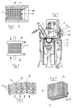
- FIG. 1 shows in principle the upper area of an internal combustion engine with a piston 1, which carries out lifting and lowering movements in a cylinder in a known manner.
- An exhaust valve 3 closes off an exhaust area 4 in the cylinder 2 or releases it in a controlled manner to expel exhaust gas.
- An exhaust manifold 5 connects to the outlet area 4.
- a catalyst body 6 is arranged in the outlet region 4 and a further catalyst body 7 in the inlet region of the outlet manifold 5.
- a correspondingly curved catalytic converter body 9 is applied to the curved piston crown 8 of the piston 1.
- FIG. 1 For simplification, three options for the arrangement of a catalyst body are shown in FIG. 1.
- the catalyst body 6 or 7 may be provided alone in connection with the catalyst body 9.
- the catalyst bodies 6 and 7 can also be provided together or alone.
- the structure of the catalyst body can be seen more clearly from FIGS. 2 and 3. As shown, it is formed from several layers 11 from a tangle of crossing wires or fibers 12 and 13. Each Layer 11 consists of a large number of longitudinal wires or fibers 12 which are connected to wires or fibers 13 running transversely thereto. To increase the surface and the stability, the wires 11, 13 can also run in a wave shape.
- a grid-like or honeycomb-like structure with a plurality of meshes 14 is formed by this configuration, through which the exhaust gas flows.
- the individual layers can also be doped with particles in the form of small chips, small fibers or coarse powders 15 (partially shown in FIG. 2).
- This doping can e.g. by shaking, by means of a liquid in the form of a carrier substance in which the particles are contained, or the like, after which the connection is made by a sintering process or by resistance welding to the wires, fibers 12, 13.
- the catalyst body according to the invention can be carried out in a known manner by a sintering process of the wires and layers placed one above the other, which are correspondingly pressed and connected to one another in a known manner in a sintering process.
- FIG. 4 An embodiment is produced in FIG. 4 in which the individual layers are placed one on top of the other and mechanically pressed together by a clamping device with an upper plate 16 and a lower plate 17 and thus held.
- the catalyst body 7 is inserted as a unit into the exhaust manifold 5 and is fixed in position by one or more stops 18 on the rear side. On the front side, it is fixed by connecting the exhaust manifold 5 to the cylinders.
- the individual layers 11 of the catalyst body can also be connected to one another by a resistance welding between two electrodes 19 and 20 to form a solid unit.
- the resistance welding process is generally known, which is why it will not be discussed in more detail here either.
- the aforementioned materials can be used individually or in mixtures.
- carbon fibers and / or carbon particles can also be added or used alone.
- the doping particles can also be used as deposits of catalytic materials, such as the light metal oxides.
- carbon fibers and / or carbon particles either alone or in a mixture with other particles for doping the catalyst brings about a further increase in heat resistance, which is decisive in the selected range.
- the carbon fibers and / or carbon particles can be the only doping material or can be applied as a mixture with the materials mentioned above.
- Ceramic fibers for example aluminum oxide fibers, can be inserted into the catalyst body in a very advantageous manner. Such fibers reduce the heat dissipation and thus bring the temperature of the catalytic converter to the required reaction temperature even faster during cold start operation of the engine. In addition, these fibers have the advantage that they also improve the mechanical stress.
- one or more heating rods 21 or heating grids can be inserted into the catalyst body (see basic illustration in FIG. 1).
Landscapes
- Chemical & Material Sciences (AREA)
- Engineering & Computer Science (AREA)
- Chemical Kinetics & Catalysis (AREA)
- Combustion & Propulsion (AREA)
- Mechanical Engineering (AREA)
- General Engineering & Computer Science (AREA)
- Health & Medical Sciences (AREA)
- Toxicology (AREA)
- Oil, Petroleum & Natural Gas (AREA)
- Organic Chemistry (AREA)
- Biomedical Technology (AREA)
- Environmental & Geological Engineering (AREA)
- Analytical Chemistry (AREA)
- General Chemical & Material Sciences (AREA)
- Materials Engineering (AREA)
- Ceramic Engineering (AREA)
- Exhaust Gas After Treatment (AREA)
- Catalysts (AREA)
- Combustion Methods Of Internal-Combustion Engines (AREA)
- Knitting Of Fabric (AREA)
- Exhaust Silencers (AREA)
Priority Applications (1)
| Application Number | Priority Date | Filing Date | Title |
|---|---|---|---|
| EP95104354A EP0665367A3 (fr) | 1991-11-12 | 1992-10-21 | Agencement d'un catalysateur pour gaz d'échappement d'un moteur à combustion interne |
Applications Claiming Priority (3)
| Application Number | Priority Date | Filing Date | Title |
|---|---|---|---|
| DE4137105A DE4137105A1 (de) | 1991-11-12 | 1991-11-12 | Anordnung eines katalysators fuer die abgase eines verbrennungsmotors |
| DE4137105 | 1991-11-12 | ||
| US07/965,800 US5425236A (en) | 1991-11-12 | 1992-10-23 | Catalyzer arrangement for the exhaust gases of an internal combustion engine |
Related Child Applications (2)
| Application Number | Title | Priority Date | Filing Date |
|---|---|---|---|
| EP95104354.6 Division-Into | 1992-10-21 | ||
| EP95104354A Division EP0665367A3 (fr) | 1991-11-12 | 1992-10-21 | Agencement d'un catalysateur pour gaz d'échappement d'un moteur à combustion interne |
Publications (3)
| Publication Number | Publication Date |
|---|---|
| EP0542002A2 true EP0542002A2 (fr) | 1993-05-19 |
| EP0542002A3 EP0542002A3 (en) | 1993-07-14 |
| EP0542002B1 EP0542002B1 (fr) | 1996-01-03 |
Family
ID=25909012
Family Applications (2)
| Application Number | Title | Priority Date | Filing Date |
|---|---|---|---|
| EP95104354A Withdrawn EP0665367A3 (fr) | 1991-11-12 | 1992-10-21 | Agencement d'un catalysateur pour gaz d'échappement d'un moteur à combustion interne |
| EP92117984A Expired - Lifetime EP0542002B1 (fr) | 1991-11-12 | 1992-10-21 | Catalyseur pour gaz d'échappement d'un moteur à combustion interne |
Family Applications Before (1)
| Application Number | Title | Priority Date | Filing Date |
|---|---|---|---|
| EP95104354A Withdrawn EP0665367A3 (fr) | 1991-11-12 | 1992-10-21 | Agencement d'un catalysateur pour gaz d'échappement d'un moteur à combustion interne |
Country Status (7)
| Country | Link |
|---|---|
| US (1) | US5425236A (fr) |
| EP (2) | EP0665367A3 (fr) |
| JP (1) | JPH06129247A (fr) |
| AT (1) | ATE132576T1 (fr) |
| CA (1) | CA2082188A1 (fr) |
| DE (2) | DE4137105A1 (fr) |
| ES (1) | ES2083052T3 (fr) |
Cited By (3)
| Publication number | Priority date | Publication date | Assignee | Title |
|---|---|---|---|---|
| EP0780550A1 (fr) * | 1995-12-18 | 1997-06-25 | Honda Giken Kogyo Kabushiki Kaisha | Système de limitation des émissions d'échappement de moteur |
| WO1997040936A1 (fr) * | 1996-04-30 | 1997-11-06 | Zentox Corporation | Support en mat de fibres et procede pour la degradation catalysee activee de maniere photochimique de composes dans un courant de fluide |
| WO1999013985A1 (fr) * | 1997-09-12 | 1999-03-25 | Institut Für Umwelttechnologie Und Umweltanalytik E.V. (Iuta) - Institut An Der Gerhard-Mercator-Universität-Gesamthochschule Duisburg | Procede et dispositif pour l'epuration catalytique d'effluents gazeux |
Families Citing this family (31)
| Publication number | Priority date | Publication date | Assignee | Title |
|---|---|---|---|---|
| DE4223277C2 (de) * | 1992-07-15 | 2001-07-19 | Linde Ag | Verfahren und Vorrichtung zur Partikelentfernung aus Abgasen von Brennkraftmaschinen |
| DE4303850C1 (de) * | 1993-02-10 | 1994-10-13 | Alfred Buck | Vorrichtung zur katalytischen Reinigung von strömenden Gasen, insbesondere von Abgasen von Verbrennungsmotoren |
| US6284201B1 (en) | 1993-02-10 | 2001-09-04 | Alfred Buck | Apparatus for the catalytic purification of flowing gases, in particular exhaust gases of internal combustion engines |
| US6058918A (en) * | 1994-08-03 | 2000-05-09 | Financieres C. Vernes | Combustion catalyst device for an internal combustion engine |
| US6176701B1 (en) * | 1997-10-01 | 2001-01-23 | Barnett Joel Robinson | Method for improving fuel efficiency in combustion chambers |
| DE19753407C2 (de) * | 1997-12-02 | 2000-08-03 | Invent Gmbh Entwicklung Neuer Technologien | Verfahren und Vorrichtung zur Umwandlung von Wärme in Arbeit |
| DE19904314A1 (de) * | 1999-01-28 | 2000-08-17 | Porsche Ag | Abgasanlage mit Katalysatoreinrichtung |
| WO2000053904A1 (fr) * | 1999-03-09 | 2000-09-14 | Abb Lummus Global, Inc. | Convertisseur catalytique de gaz d'echappement |
| WO2001000323A1 (fr) * | 1999-06-29 | 2001-01-04 | Abb Lummus Global, Inc. | Procede de revetement d'un materiau fibreux metallique |
| US6667017B2 (en) | 1999-10-15 | 2003-12-23 | Abb Lummus Global, Inc. | Process for removing environmentally harmful compounds |
| WO2001028665A1 (fr) * | 1999-10-15 | 2001-04-26 | Abb Lummus Global, Inc. | Conversion d'oxydes d'azote en presence d'un catalyseur sur support a structure de type a mailles |
| RU2175393C2 (ru) * | 2000-01-05 | 2001-10-27 | Военный автомобильный институт | Устройство для отвода отработавших газов двигателя внутреннего сгорания |
| DE10016841A1 (de) * | 2000-04-05 | 2001-10-18 | Drafas Gmbh | Formbarer Maschengewebeverbund |
| AU2002339266A1 (en) * | 2001-10-10 | 2003-04-22 | Dominique Bosteels | Combustion process |
| US20040177609A1 (en) * | 2001-12-07 | 2004-09-16 | Moore Dan T. | Insulated exhaust manifold having ceramic inner layer that is highly resistant to thermal cycling |
| AU2002346693A1 (en) * | 2001-12-07 | 2003-06-23 | Dan T. Moore Company | Insulated exhaust manifold having internal catalyst support body |
| US6725656B2 (en) | 2001-12-07 | 2004-04-27 | Dan T. Moore Company | Insulated exhaust manifold |
| ITTO20030059A1 (it) * | 2003-01-31 | 2004-08-01 | Fiat Ricerche | Motore diesel ad iniezione diretta, con combustione |
| DE10337265A1 (de) * | 2003-08-13 | 2005-03-10 | Emitec Emissionstechnologie | Rollnahtgeschweißter Körper zur Abgasbehandlung |
| JP3955291B2 (ja) * | 2004-07-13 | 2007-08-08 | 株式会社共立 | 内燃エンジンの触媒付きマフラー |
| JPWO2006080441A1 (ja) * | 2005-01-28 | 2008-06-19 | 株式会社平岡製作所 | 小型エンジン用のマフラー |
| DE102005023384A1 (de) * | 2005-05-17 | 2006-11-23 | Emitec Gesellschaft Für Emissionstechnologie Mbh | Verfahren und Vorrichtung zum Verschweißen metallischer Fasern zu einem Vließ |
| DE102005023385A1 (de) * | 2005-05-17 | 2006-11-23 | Emitec Gesellschaft Für Emissionstechnologie Mbh | Fügen metallischer Fasern zu Vliesen zur Herstellung von Wabenkörpern |
| DE102006001833A1 (de) * | 2006-01-13 | 2007-07-19 | Emitec Gesellschaft Für Emissionstechnologie Mbh | Diskontinuierliches Verschweißen von metallischen Fasern |
| SG183687A1 (en) | 2007-08-03 | 2012-09-27 | Errcive Inc | Porous bodies and methods |
| DE102008027328A1 (de) | 2008-06-07 | 2009-12-10 | Volkswagen Ag | Abgasstrang einer Verbrennungskraftmaschine mit einer Abgasreinigungsanlage |
| US8277743B1 (en) | 2009-04-08 | 2012-10-02 | Errcive, Inc. | Substrate fabrication |
| US8359829B1 (en) | 2009-06-25 | 2013-01-29 | Ramberg Charles E | Powertrain controls |
| US9833932B1 (en) | 2010-06-30 | 2017-12-05 | Charles E. Ramberg | Layered structures |
| WO2019195406A1 (fr) | 2018-04-04 | 2019-10-10 | Unifrax | Llc | Fibres poreuses activées et produits les comprenant |
| DE102018112836A1 (de) | 2018-05-29 | 2018-07-12 | FEV Europe GmbH | Zylinderkopf einer Verbrennungskraftmaschine |
Family Cites Families (67)
| Publication number | Priority date | Publication date | Assignee | Title |
|---|---|---|---|---|
| US3124930A (en) * | 1964-03-17 | Exhaust system | ||
| US1793813A (en) * | 1926-10-20 | 1931-02-24 | Mackinnon Daniel Albert | Means for neutralizing poisonous engine gases |
| BE369912A (fr) * | 1929-12-04 | |||
| US2267918A (en) * | 1940-03-27 | 1941-12-30 | Gen Motors Corp | Porous article and method of making same |
| FR992440A (fr) * | 1948-08-16 | 1951-10-18 | Alliance Europ | Perfectionnements apportés aux moteurs à combustion interne |
| US3161478A (en) * | 1959-05-29 | 1964-12-15 | Horst Corp Of America V D | Heat resistant porous structure |
| US3087233A (en) * | 1960-11-16 | 1963-04-30 | Fram Corp | Pervious metal fiber material and method of making the same |
| FR1358557A (fr) * | 1963-03-05 | 1964-04-17 | Commissariat Energie Atomique | Catalyseur de combustion et son procédé de fabrication |
| US3306353A (en) * | 1964-12-23 | 1967-02-28 | Olin Mathieson | Heat exchanger with sintered metal matrix around tubes |
| FR1453653A (fr) * | 1965-11-12 | 1966-06-03 | Dunlop Rubber Co | Filtre pour gaz et liquides |
| US3819334A (en) * | 1970-10-27 | 1974-06-25 | Mitsui Mining & Smelting Co | Catalytic reaction apparatus for purifying waste gases containing carbon monoxide |
| US3648676A (en) * | 1971-03-17 | 1972-03-14 | Environmental Quality Engineer | Process for reducing detonation |
| FR2145340A5 (fr) * | 1971-07-08 | 1973-02-16 | Hinderks M V | |
| US3927525A (en) * | 1973-05-25 | 1975-12-23 | Gen Motors Corp | Engine with exhaust manifold converter-reactor |
| DE2430983A1 (de) * | 1973-07-12 | 1975-01-30 | Inst Ciezkiej Syntezy Orga | Verbrennungsmotor, der verbrennungsgase mit erniedrigtem gehalt an toxischen bestandteilen emittiert |
| US3904551A (en) * | 1973-12-19 | 1975-09-09 | Grace W R & Co | Process for preparing an auto exhaust catalytic converter |
| US4064914A (en) * | 1974-05-08 | 1977-12-27 | Union Carbide Corporation | Porous metallic layer and formation |
| US4062807A (en) * | 1975-06-17 | 1977-12-13 | Tokyo Shibaura Electric Co., Ltd. | Nitrogen oxide reducing catalyst |
| GB1578027A (en) * | 1976-06-10 | 1980-10-29 | Ricardo Consulting Engs Ltd | Ic engines having catalytic ignition |
| US4183896A (en) * | 1976-06-16 | 1980-01-15 | Gordon Donald C | Anti-pollution device for exhaust gases |
| GB1567593A (en) * | 1976-10-20 | 1980-05-21 | Matsushita Electric Industrial Co Ltd | Exhaust gas control equipment |
| GB1560311A (en) * | 1978-02-13 | 1980-02-06 | Secr Defence | Combustion chamber components |
| JPS54128842A (en) * | 1978-03-29 | 1979-10-05 | Bridgestone Corp | Thermal collector |
| JPS54152241A (en) * | 1978-04-20 | 1979-11-30 | Mtp Kasei Kk | Solar heat collecting body |
| DE2853547C2 (de) * | 1978-12-12 | 1983-11-03 | Degussa Ag, 6000 Frankfurt | Von Strömungskanälen durchzogener Träger für Katalysatoren mit Querstromeffekt und Verwendung |
| US4301012A (en) * | 1979-04-25 | 1981-11-17 | Purolator Technologies, Inc. | Welded stainless steel mesh cleanable filter |
| FR2462188A1 (fr) * | 1979-07-25 | 1981-02-13 | Tissmetal Lionel Dupont | Filtre a support textile et son procede de fabrication |
| DE2951316A1 (de) * | 1979-12-20 | 1981-07-02 | Degussa Ag, 6000 Frankfurt | Katalytisches filter fuer die dieselabgasreinigung |
| JPS577216A (en) * | 1980-06-16 | 1982-01-14 | Ngk Insulators Ltd | Ceramic honeycomb filter and preparation thereof |
| US4329162A (en) * | 1980-07-03 | 1982-05-11 | Corning Glass Works | Diesel particulate trap |
| US4359864A (en) * | 1981-02-05 | 1982-11-23 | Caterpillar Tractor Co. | Burn-out type cleaning means for particulate filter of engine exhaust system |
| US4811707A (en) * | 1981-03-30 | 1989-03-14 | Pfefferle William C | Method of operating catalytic ignition engines and apparatus therefor |
| AU540009B2 (en) * | 1982-02-16 | 1984-10-25 | Matsushita Electric Industrial Co., Ltd. | Exhaust gas filter |
| US4417908A (en) * | 1982-02-22 | 1983-11-29 | Corning Glass Works | Honeycomb filter and method of making it |
| DE3232729A1 (de) * | 1982-09-03 | 1984-03-08 | Degussa Ag, 6000 Frankfurt | Verfahren zur herabsetzung der zuendtemperatur von aus dem abgas von dieselmotoren herausgefiltertem dieselruss |
| DE3331579A1 (de) * | 1983-09-01 | 1985-03-21 | Klöckner-Humboldt-Deutz AG, 5000 Köln | Kolbenbrennkraftmaschine |
| FR2551494A1 (fr) * | 1983-09-07 | 1985-03-08 | Kervagoret Alain | Procede pour ameliorer le fonctionnement d'un moteur a combustion interne, dispositif pour la mise en oeuvre de ce procede et moteur a combustion interne equipe de ce dispositif |
| US4662915A (en) * | 1984-07-09 | 1987-05-05 | Takeda Chemical Industries, Ltd. | Powder-air separator for use in a powder filling apparatus |
| DE3509969A1 (de) * | 1985-03-20 | 1985-11-21 | Friedrich 5000 Köln Elles | Abgaskatalysatorpatrone zur nachverbrennung und schalldaempfung an brennkraftmaschinen |
| JPS61287451A (ja) * | 1985-06-13 | 1986-12-17 | Nippon Denso Co Ltd | 排ガス浄化用触媒担体 |
| JPH062204B2 (ja) * | 1985-06-24 | 1994-01-12 | 日本電装株式会社 | セラミツク構造体 |
| DE3527111A1 (de) * | 1985-07-29 | 1987-01-29 | Interatom | Metallischer, gewickelter abgaskatalysatortraegerkoerper mit geometrisch komplizierter form des querschnitts sowie verfahren, vorrichtung und rohling zu seiner herstellung |
| DE3533924A1 (de) * | 1985-09-24 | 1987-06-19 | Schumacher Sche Fab Verwalt | Filterkoerper und verfahren zu dessen herstellung |
| US4725411A (en) * | 1985-11-12 | 1988-02-16 | W. R. Grace & Co. | Device for physical and/or chemical treatment of fluids |
| ES2040246T3 (es) * | 1986-02-25 | 1993-10-16 | Coventry University | Motor de combustion interna. |
| JPH0657288B2 (ja) * | 1986-03-25 | 1994-08-03 | 旭硝子株式会社 | パテイキユレ−トトラツプ |
| DE3614347A1 (de) * | 1986-04-28 | 1987-10-29 | Didier Werke Ag | Katalysatorbaustein |
| US4687579A (en) * | 1986-05-02 | 1987-08-18 | The United States Of America As Represented By The United States Department Of Energy | Sintered composite medium and filter |
| DE3739081A1 (de) * | 1986-11-21 | 1988-06-01 | Fischer Ag Georg | Einrichtung zur schalldaempfung bei verbrennungsaggregaten |
| FR2615247B3 (fr) * | 1987-05-11 | 1989-10-20 | Stahl Frederic | Procede de traitement des gaz de combustion des moteurs a combustion interne |
| US4758272A (en) * | 1987-05-27 | 1988-07-19 | Corning Glass Works | Porous metal bodies |
| US4869738A (en) * | 1987-08-26 | 1989-09-26 | W. R. Grace & Co.-Conn. | Particulate trap |
| DE3818281A1 (de) * | 1988-03-10 | 1989-09-21 | Schwaebische Huettenwerke Gmbh | Abgasfilter |
| US4942020A (en) * | 1988-06-27 | 1990-07-17 | W.R. Grace & Co.-Conn. | Converter for removing pollutants from a gas stream |
| DE3828348A1 (de) * | 1988-08-20 | 1990-02-22 | Schwaebische Huettenwerke Gmbh | Vorrichtung zur waermeuebertragung |
| DE3828347A1 (de) * | 1988-08-20 | 1990-03-01 | Schwaebische Huettenwerke Gmbh | Abgasfilter fuer heizungs- oder verbrennungsanlagen |
| EP0396650B2 (fr) * | 1988-09-02 | 1995-04-12 | GebràDer Sulzer Aktiengesellschaft | Dispositif de mise en uvre de reactions catalysees |
| DE3901609A1 (de) * | 1989-01-20 | 1990-07-26 | Schwaebische Huettenwerke Gmbh | Abgasfilter |
| DE3908581A1 (de) * | 1989-03-16 | 1990-09-20 | Schwaebische Huettenwerke Gmbh | Verfahren zur herstellung eines filter- oder katalysatorkoerpers |
| IT1232749B (it) * | 1989-04-12 | 1992-03-05 | I R T I Istituto Di Ricerca E | Depuratore di gas di scarico ad attivita`catalitica e silenziatore per motori a combustione interna |
| DE3925596A1 (de) * | 1989-08-02 | 1991-02-07 | Schwaebische Huettenwerke Gmbh | Verfahren zur herstellung eines filters und danach hergestellter filter |
| DE3932809A1 (de) * | 1989-08-19 | 1991-05-08 | Schreiber Hans | Verschluss fuer behaeltnisse, insbesondere trinkgefaesse |
| FR2651150B1 (fr) * | 1989-08-30 | 1994-01-14 | Onera | Element pour la filtration et/ou l'epuration de gaz chauds, et son procede de fabrication. |
| DE3928790A1 (de) * | 1989-08-31 | 1991-03-07 | Didier Werke Ag | Verfahren zum herstellen einer katalysatorplatte und stuetzgeruest zur herstellung einer katalysatorplatte |
| US5089236A (en) * | 1990-01-19 | 1992-02-18 | Cummmins Engine Company, Inc. | Variable geometry catalytic converter |
| US5070694A (en) * | 1990-10-31 | 1991-12-10 | W. R. Grace & Co. -Conn. | Structure for electrically heatable catalytic core |
| DE4110285A1 (de) * | 1991-03-28 | 1992-10-01 | Schwaebische Huettenwerke Gmbh | Filter- oder katalysatorkoerper |
-
1991
- 1991-11-12 DE DE4137105A patent/DE4137105A1/de not_active Withdrawn
-
1992
- 1992-10-21 ES ES92117984T patent/ES2083052T3/es not_active Expired - Lifetime
- 1992-10-21 AT AT92117984T patent/ATE132576T1/de active
- 1992-10-21 EP EP95104354A patent/EP0665367A3/fr not_active Withdrawn
- 1992-10-21 DE DE59204913T patent/DE59204913D1/de not_active Expired - Fee Related
- 1992-10-21 EP EP92117984A patent/EP0542002B1/fr not_active Expired - Lifetime
- 1992-10-23 US US07/965,800 patent/US5425236A/en not_active Expired - Fee Related
- 1992-11-05 CA CA002082188A patent/CA2082188A1/fr not_active Abandoned
- 1992-11-12 JP JP4302432A patent/JPH06129247A/ja active Pending
Cited By (6)
| Publication number | Priority date | Publication date | Assignee | Title |
|---|---|---|---|---|
| EP0780550A1 (fr) * | 1995-12-18 | 1997-06-25 | Honda Giken Kogyo Kabushiki Kaisha | Système de limitation des émissions d'échappement de moteur |
| US5916132A (en) * | 1995-12-18 | 1999-06-29 | Honda Giken Kogyo K.K. | Engine exhaust emission control system utilizing a catalyst carried in a porous flexible bag |
| WO1997040936A1 (fr) * | 1996-04-30 | 1997-11-06 | Zentox Corporation | Support en mat de fibres et procede pour la degradation catalysee activee de maniere photochimique de composes dans un courant de fluide |
| GB2328384A (en) * | 1996-04-30 | 1999-02-24 | Zentox Corp | Fibrous matte support and method for the photopromoted catalyzed degradation of compounds in a fluid stream |
| GB2328384B (en) * | 1996-04-30 | 2000-03-29 | Zentox Corp | Fibrous matte support and method for the photopromoted catalyzed degradation of compounds in a fluid stream |
| WO1999013985A1 (fr) * | 1997-09-12 | 1999-03-25 | Institut Für Umwelttechnologie Und Umweltanalytik E.V. (Iuta) - Institut An Der Gerhard-Mercator-Universität-Gesamthochschule Duisburg | Procede et dispositif pour l'epuration catalytique d'effluents gazeux |
Also Published As
| Publication number | Publication date |
|---|---|
| DE4137105A1 (de) | 1993-05-13 |
| ATE132576T1 (de) | 1996-01-15 |
| JPH06129247A (ja) | 1994-05-10 |
| EP0542002A3 (en) | 1993-07-14 |
| EP0665367A3 (fr) | 1995-09-13 |
| EP0542002B1 (fr) | 1996-01-03 |
| ES2083052T3 (es) | 1996-04-01 |
| US5425236A (en) | 1995-06-20 |
| EP0665367A2 (fr) | 1995-08-02 |
| DE59204913D1 (de) | 1996-02-15 |
| CA2082188A1 (fr) | 1993-05-13 |
Similar Documents
| Publication | Publication Date | Title |
|---|---|---|
| EP0542002A2 (fr) | Catalyseur pour gaz d'échappement d'un moteur à combustion interne | |
| DE602004011378T3 (de) | Wabenstrukturkörper | |
| DE602004011971T3 (de) | Wabenstruktur | |
| DE60200673T2 (de) | Filter zum Reinigen von Abgas | |
| DE69610022T2 (de) | Partikelfalle für einen Dieselmotor | |
| EP0505832B1 (fr) | Corps filtrant ou catalytique | |
| DE102018203459A1 (de) | Verschlossene Wabenstruktur | |
| DE3043995A1 (de) | Abgasdurchstroemter schwebeteilchenfilter fuer dieselmaschinen | |
| DE4022937A1 (de) | Filter- oder katalysatorkoerper | |
| DE3043996A1 (de) | Abgasdurchstroemter schwebeteilchenfilter fuer dieselmaschien | |
| DE2853547A1 (de) | Traegermatrix fuer katalysatoren | |
| EP0291704A1 (fr) | Revêtement à effet catalytique de materiau filtrant pour filtre à suie de moteur Diesel | |
| DE2224679A1 (de) | Vorrichtung zum katalytischen Reinigen von Gasen | |
| DE112008000035T5 (de) | Wabenstruktur | |
| EP0635098B1 (fr) | Dispositif d'epuration catalytique de gaz en ecoulement, notamment de gaz d'echappement de moteurs a combustion interne | |
| DD297484A5 (de) | Element zur filtration und/oder reinigung von abgasen und verfahren zur herstellung | |
| DE3436400A1 (de) | Verfahren zum herstellen eines katalysators fuer die reinigung der abgase von verbrennungskraftmaschinen | |
| EP0542124A1 (fr) | Silencieux | |
| EP0086367B1 (fr) | Dispositif de nettoyage des gaz d'échappement des moteurs Diesel, particulièrement pour véhicules | |
| DE3437641C2 (de) | Abgaskatalysator | |
| DE102020216573A1 (de) | Verbundoxidkatalysator, poröser verbundstoff und verfahren zur herstellung eines verbundoxidkatalysators | |
| DE3415075C2 (de) | Vorrichtung zur Reinigung von Abgasen, insbesondere für Dieselmotoren | |
| DE69419911T2 (de) | Katalysatorsystem und ihre anwendung | |
| DE2908671A1 (de) | Verbesserte traegermatrix fuer katalysatoren | |
| DE10133231B4 (de) | Oxidationskatalysator für Abgase einer Verbrennungskraftmaschine |
Legal Events
| Date | Code | Title | Description |
|---|---|---|---|
| PUAI | Public reference made under article 153(3) epc to a published international application that has entered the european phase |
Free format text: ORIGINAL CODE: 0009012 |
|
| AK | Designated contracting states |
Kind code of ref document: A2 Designated state(s): AT BE DE ES FR GB IT NL SE |
|
| PUAL | Search report despatched |
Free format text: ORIGINAL CODE: 0009013 |
|
| AK | Designated contracting states |
Kind code of ref document: A3 Designated state(s): AT BE DE ES FR GB IT NL SE |
|
| 17P | Request for examination filed |
Effective date: 19931022 |
|
| 17Q | First examination report despatched |
Effective date: 19941011 |
|
| GRAA | (expected) grant |
Free format text: ORIGINAL CODE: 0009210 |
|
| AK | Designated contracting states |
Kind code of ref document: B1 Designated state(s): AT BE DE ES FR GB IT NL SE |
|
| REF | Corresponds to: |
Ref document number: 132576 Country of ref document: AT Date of ref document: 19960115 Kind code of ref document: T |
|
| XX | Miscellaneous (additional remarks) |
Free format text: TEILANMELDUNG 95104354.6 EINGEREICHT AM 21/10/92. |
|
| REF | Corresponds to: |
Ref document number: 59204913 Country of ref document: DE Date of ref document: 19960215 |
|
| GBT | Gb: translation of ep patent filed (gb section 77(6)(a)/1977) |
Effective date: 19960223 |
|
| REG | Reference to a national code |
Ref country code: ES Ref legal event code: FG2A Ref document number: 2083052 Country of ref document: ES Kind code of ref document: T3 |
|
| ITF | It: translation for a ep patent filed | ||
| ET | Fr: translation filed | ||
| PGFP | Annual fee paid to national office [announced via postgrant information from national office to epo] |
Ref country code: AT Payment date: 19960917 Year of fee payment: 5 |
|
| PGFP | Annual fee paid to national office [announced via postgrant information from national office to epo] |
Ref country code: BE Payment date: 19961010 Year of fee payment: 5 |
|
| PGFP | Annual fee paid to national office [announced via postgrant information from national office to epo] |
Ref country code: ES Payment date: 19961015 Year of fee payment: 5 |
|
| PGFP | Annual fee paid to national office [announced via postgrant information from national office to epo] |
Ref country code: SE Payment date: 19961018 Year of fee payment: 5 Ref country code: GB Payment date: 19961018 Year of fee payment: 5 |
|
| PGFP | Annual fee paid to national office [announced via postgrant information from national office to epo] |
Ref country code: DE Payment date: 19961023 Year of fee payment: 5 |
|
| PGFP | Annual fee paid to national office [announced via postgrant information from national office to epo] |
Ref country code: NL Payment date: 19961029 Year of fee payment: 5 |
|
| PGFP | Annual fee paid to national office [announced via postgrant information from national office to epo] |
Ref country code: FR Payment date: 19961030 Year of fee payment: 5 |
|
| PLBE | No opposition filed within time limit |
Free format text: ORIGINAL CODE: 0009261 |
|
| STAA | Information on the status of an ep patent application or granted ep patent |
Free format text: STATUS: NO OPPOSITION FILED WITHIN TIME LIMIT |
|
| 26N | No opposition filed | ||
| PG25 | Lapsed in a contracting state [announced via postgrant information from national office to epo] |
Ref country code: GB Free format text: LAPSE BECAUSE OF NON-PAYMENT OF DUE FEES Effective date: 19971021 Ref country code: AT Free format text: LAPSE BECAUSE OF NON-PAYMENT OF DUE FEES Effective date: 19971021 |
|
| PG25 | Lapsed in a contracting state [announced via postgrant information from national office to epo] |
Ref country code: SE Free format text: LAPSE BECAUSE OF NON-PAYMENT OF DUE FEES Effective date: 19971022 Ref country code: ES Free format text: LAPSE BECAUSE OF EXPIRATION OF PROTECTION Effective date: 19971022 |
|
| PG25 | Lapsed in a contracting state [announced via postgrant information from national office to epo] |
Ref country code: FR Free format text: THE PATENT HAS BEEN ANNULLED BY A DECISION OF A NATIONAL AUTHORITY Effective date: 19971031 Ref country code: BE Free format text: LAPSE BECAUSE OF NON-PAYMENT OF DUE FEES Effective date: 19971031 |
|
| BERE | Be: lapsed |
Owner name: SCHWABISCHE HUTTENWERKE G.M.B.H. Effective date: 19971031 |
|
| PG25 | Lapsed in a contracting state [announced via postgrant information from national office to epo] |
Ref country code: NL Free format text: LAPSE BECAUSE OF NON-PAYMENT OF DUE FEES Effective date: 19980501 |
|
| GBPC | Gb: european patent ceased through non-payment of renewal fee |
Effective date: 19971021 |
|
| NLV4 | Nl: lapsed or anulled due to non-payment of the annual fee |
Effective date: 19980501 |
|
| PG25 | Lapsed in a contracting state [announced via postgrant information from national office to epo] |
Ref country code: DE Free format text: LAPSE BECAUSE OF NON-PAYMENT OF DUE FEES Effective date: 19980701 |
|
| EUG | Se: european patent has lapsed |
Ref document number: 92117984.2 |
|
| REG | Reference to a national code |
Ref country code: FR Ref legal event code: ST |
|
| REG | Reference to a national code |
Ref country code: ES Ref legal event code: FD2A Effective date: 20010201 |
|
| PG25 | Lapsed in a contracting state [announced via postgrant information from national office to epo] |
Ref country code: IT Free format text: LAPSE BECAUSE OF NON-PAYMENT OF DUE FEES;WARNING: LAPSES OF ITALIAN PATENTS WITH EFFECTIVE DATE BEFORE 2007 MAY HAVE OCCURRED AT ANY TIME BEFORE 2007. THE CORRECT EFFECTIVE DATE MAY BE DIFFERENT FROM THE ONE RECORDED. Effective date: 20051021 |