EP0542077A1 - Gangschaltungsvorrichtung für Fahrrad - Google Patents
Gangschaltungsvorrichtung für Fahrrad Download PDFInfo
- Publication number
- EP0542077A1 EP0542077A1 EP92118725A EP92118725A EP0542077A1 EP 0542077 A1 EP0542077 A1 EP 0542077A1 EP 92118725 A EP92118725 A EP 92118725A EP 92118725 A EP92118725 A EP 92118725A EP 0542077 A1 EP0542077 A1 EP 0542077A1
- Authority
- EP
- European Patent Office
- Prior art keywords
- speed change
- link
- movable member
- bicycle
- chain
- Prior art date
- Legal status (The legal status is an assumption and is not a legal conclusion. Google has not performed a legal analysis and makes no representation as to the accuracy of the status listed.)
- Ceased
Links
- 230000008859 change Effects 0.000 title claims abstract description 72
- 230000007246 mechanism Effects 0.000 claims abstract description 41
- 230000008901 benefit Effects 0.000 description 4
- 238000013459 approach Methods 0.000 description 2
- 238000006073 displacement reaction Methods 0.000 description 2
- 230000001351 cycling effect Effects 0.000 description 1
- 230000003247 decreasing effect Effects 0.000 description 1
- 230000000694 effects Effects 0.000 description 1
- 230000002452 interceptive effect Effects 0.000 description 1
- 230000004044 response Effects 0.000 description 1
- 239000013585 weight reducing agent Substances 0.000 description 1
Images


Classifications
-
- B—PERFORMING OPERATIONS; TRANSPORTING
- B62—LAND VEHICLES FOR TRAVELLING OTHERWISE THAN ON RAILS
- B62M—RIDER PROPULSION OF WHEELED VEHICLES OR SLEDGES; POWERED PROPULSION OF SLEDGES OR SINGLE-TRACK CYCLES; TRANSMISSIONS SPECIALLY ADAPTED FOR SUCH VEHICLES
- B62M9/00—Transmissions characterised by use of an endless chain, belt, or the like
- B62M9/04—Transmissions characterised by use of an endless chain, belt, or the like of changeable ratio
- B62M9/06—Transmissions characterised by use of an endless chain, belt, or the like of changeable ratio using a single chain, belt, or the like
- B62M9/10—Transmissions characterised by use of an endless chain, belt, or the like of changeable ratio using a single chain, belt, or the like involving different-sized wheels, e.g. rear sprocket chain wheels selectively engaged by the chain, belt, or the like
- B62M9/12—Transmissions characterised by use of an endless chain, belt, or the like of changeable ratio using a single chain, belt, or the like involving different-sized wheels, e.g. rear sprocket chain wheels selectively engaged by the chain, belt, or the like the chain, belt, or the like being laterally shiftable, e.g. using a rear derailleur
- B62M9/121—Rear derailleurs
- B62M9/124—Mechanisms for shifting laterally
- B62M9/1244—Mechanisms for shifting laterally limiting or positioning the movement
- B62M9/1246—Mechanisms for shifting laterally limiting or positioning the movement using cams or plates
-
- B—PERFORMING OPERATIONS; TRANSPORTING
- B62—LAND VEHICLES FOR TRAVELLING OTHERWISE THAN ON RAILS
- B62M—RIDER PROPULSION OF WHEELED VEHICLES OR SLEDGES; POWERED PROPULSION OF SLEDGES OR SINGLE-TRACK CYCLES; TRANSMISSIONS SPECIALLY ADAPTED FOR SUCH VEHICLES
- B62M9/00—Transmissions characterised by use of an endless chain, belt, or the like
- B62M9/04—Transmissions characterised by use of an endless chain, belt, or the like of changeable ratio
- B62M9/06—Transmissions characterised by use of an endless chain, belt, or the like of changeable ratio using a single chain, belt, or the like
- B62M9/10—Transmissions characterised by use of an endless chain, belt, or the like of changeable ratio using a single chain, belt, or the like involving different-sized wheels, e.g. rear sprocket chain wheels selectively engaged by the chain, belt, or the like
- B62M9/12—Transmissions characterised by use of an endless chain, belt, or the like of changeable ratio using a single chain, belt, or the like involving different-sized wheels, e.g. rear sprocket chain wheels selectively engaged by the chain, belt, or the like the chain, belt, or the like being laterally shiftable, e.g. using a rear derailleur
- B62M9/121—Rear derailleurs
- B62M9/124—Mechanisms for shifting laterally
- B62M9/1242—Mechanisms for shifting laterally characterised by the linkage mechanisms
Definitions
- the present invention relates to a bicycle speed change assembly.
- a prior art bicycle rear derailleur a has a chain guide d which rotatably supports a guide pulley b and a tension pulley c.
- This chain guide d is supported, via a shift link mechanism such as a parallelogram pantograph mechanism g, on a rear end plate e at an end portion of a bicycle frame, or on a bracket f attached to the rear end plate e so as to pivot about a predetermined axis while being urged in a direction to tension a chain C.
- a shift link mechanism such as a parallelogram pantograph mechanism g
- the pantograph mechanism g includes: a link base h supported by the bracket f; inner and outer link members i, j which are pivotally connected at their respective base end portions to the link base h and extended forwardly of the bicycle; and a movable member k which is pivotally connected to each free end portions of the link members i, j.
- the movable member k rotatably supports the chain guide d.
- the chain guide d is elastically urged by a coil spring (not shown in Figs.) in a direction to tension the chain C, i.e. in a clockwise direction in Fig. 7. This removes slack in the chain C and gives the chain C a predetermined level of tension.
- an edge of the guide pulley b and an edge of each sprocket m of the sprocket cluster M should be within appropriate proximity. This is because the guide pulley b is directly responsible for shifting a portion of the chain ahead of the sprocket cluster M from a sprocket presently engaged with the chain to a target sprocket, and if the edge of the guide pulley b is too far away from the edge of the sprocket cluster M, the guide pulley b will have to travel over a long distance for completing a chain shift operation, resulting in a poor derailleur response.
- the guide pulley b would maintain a subtantially constant distance with each opposing sprocket m of the sprocket cluster M while the guide pulley moves over an entire range of its travel.
- the chain guide d should not move in parallel with the hub shaft n, but shoud move substantially in parallel with a line running through an edge of each sprocket m of the sprocket cluster M.
- the rear sprocket cluster M is usually configured in a manner that a sprocket of a greater diameter is placed closer to the hub shaft, it is necessary for the guide pulley b to moved away from the hub shaft n as it moves axially inward of the hub.
- a prior art bicycle derailleur a the above-described purpose is achieved in the following means: As shown in Fig. 7, in a prior art bicycle dereilleur a, the link base h is supported below the hub shaft n, and from this link base h, the inner and outer link members i, j are extended forwardly of the bicycle to configure the pantograph mechanism g, in which connecting pins p, q of the inner and outer link members i, j are slanted off the vertical by a predetermined angle, or otherwise, the link base h is supported pivotally about the bracket f. With this arrangement, it is possible to move the guide pulley b in a manner as shown in Fig. 6, that the guide pulley b travels rearwardly downward of the bicycle as it moves axially inward of the hub shaft, so that the distance between the edge of the guide pulley b and the edge of each sprocket m is maintained substantially constant.
- a bicycle speed change assembly comprising: a pantogtaph link mechanism including a link base supported on a chain stay ahead of a sprocket cluster mounted on a hub shaft, inner and outer links each having a base end pivoted to the link base and extending rearward, and a movable member pivoted to respective free ends of these inner and outer links; a chain guide rotatably supporting a guide pulley and a tension pulley, supported on the movable member of the pantograph mechanism to pivot about a shaft in parallel to the hub shaft while being elastically urged to tension a chain; and a guide pulley travel control means for moving the guide pulley inward axially of the hub shaft and forwardly downward substantially along a radial path of the sprocket cluster when the pantograph mechanism is deformed.
- the pivotal movement required of the inner and outer link mambers is smaller than before, making it possible to reduce the size of the speed change assembly.
- the amount of pull needed for the control cable is also smaller, resulting in remarkably improved efficiency and operatability in the speed change operation, making it possible to reduce the size of the control lever assembly.
- speed change assembly is mounted below a chain stay, the speed change assembly is not an outermost component of the bicycle width. This provides less chance for major damage to the speed change assembly in case of a bicycle rollover.
- the present invention provides a bicycle speed change assembly comprising: a pantogtaph link mechanism including a link base supported on a chain stay ahead of a sprocket cluster mounted on a hub shaft, inner and outer link members each extending rearward, and having a base end pivoted by a connecting pin to the link base, and a movable member pivoted by connecting pins to respective free ends of the inner and outer link members; and a chain guide rotatably supporting a guide pulley and a tension pulley, the chain guide being supported on the movable member of the pantograph mechanism to pivot about an axis in parallel with the hub shaft while being elastically urged to tension a chain.
- the present invention is characterised in the following means:
- Each of the connecting pins is slanted off the vertical for moving the guide pulley inward axially of the hub shaft and forwardly downwardly of the sprocket cluster when the pantograph mechanism is deformed, and each of the inner and outer link members have a top surface, a plane containing at least a portion of the top surface of the inner link member adjacent to the movable member is displaced downward axially of the connecting pins from another ploane containing a portion of the top surface of the outer link member adjacent to the movable member.
- Fig. 1 is a side view of a speed change assembly according to the present invention.
- Fig. 2 is a view of the speed change assembly shown in Fig. 1 as viewed from a direction indicated by Arrow II.
- Fig. 3 is a schematic drawing to show function of a pantograph mechanism according to the present invention.
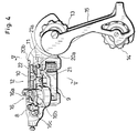
- Fig. 4 is a rear view of the speed change assembly shown in Fig. 1.
- Fig. 5 is a schematic drawing to show function of a speed change assembly according to the present invention.
- Fig. 6 is a schematic drawing to show function of a conventional speed change assembly.
- Fig. 7 is a view of a conventional speed change assembly.
- FIGs. 1 and 2 show a rear portion of a bicycle to which a speed change assembly 1 according to the present invention is mounted.
- the speed change assembly 1 is mounted ahead of the hub shaft 4 or the sprocket cluster 2.
- the speed change assembly 1 has a pantograph mechanism including: a link base 8 which is supported at an intermediate portion of a chain stay 7 extending forward from the rear end plate 6; an inner link member 9 and an outer link member 10, each having a base end portion pivotally connected to the link base 8; and a movable member 11 which is pivotally connected to each free end portion of the inner and outer link members 9, 10.
- a chain guide 15 which rotatably supports a guide pulley 13 and a tension pulley 14, is rotatably supported while being urged to tension a chain C about an axis in parallel to the hub shaft 4.
- a control cable T comprises an inner cable t1 and an outer sheath t2.
- An end of the outer sheath t2 is fastened at a predetermined location on the bicycle frame (not shown in Figs.) whereas the inner cable t1, which extends out of the outer sheath t2, is fastened to a cable connecting means 16 provided above an area where the inner link member 9 is connected to the link base 8.
- the pantograph link mechanism 12 deforms to perform speed change operation.
- the pantograph link mechanism 12 is provided with a speed change cam 17 at a base end portion (an end portion closer to the link base) of the inner link member 9.
- the speed change cam 17 is a cylindrical type, having, as a cam face, a circumference having varied radial distance. The cam face of the speed change cam 17 is contacted by a cam follower 18 mounted on the outer link member 10.
- the cable connection means 16 allows an end portion of the inner cable t1, first, to wind around a reel portion 16b formed on an outer wall of the rotating member 16a, and then, to fasten to a fastening means 16c formed on the outer wall of the rotating member 16a. Residual end portion of the inner cable t1 may be wound and held around a rotational shaft on a top surface of the rotating member 16a.
- the cable connection means 16 and the speed change cam 17 rotate integrally when pulled by the inner cable t1.
- the speed change cam 17 rotates to change a contact point between the speed change cam 17 and the cam follower 18, thereby deforming the pantograph mechanism 12 laterally.
- the link base 8 is mounted via a bracket 19 which is welded to a predetermined location on the chain stay 7.
- the connecting pins 20a, 20b of the inner and outer link members 9, 10 of the pantograph mechanism 12 are slanted by an appropriate angle ⁇ off the vertical, as shown in Fig. 2, so that the guide pulley 13 can displace in a predetermined direction.
- the guide pulley 13 moves along a generatrix of the frustum, the chain's engagement angle with a sprocket will not vary widely from the largest sprocket through the smallest sprocket, even when the sprocket cluster has a substantial diametral difference between the largest and the smallest sprockets, resulting in ensured appropriateness in speed changing operation.
- control lever now needs smaller rotational travel, it is also possible to reduce the size of the speed change lever assembly.
- Still another advantage of this embodiment is that, as shown in Figs. 1 and 2, the speed change assembly 1 will not stick out of the width of the bicycle as has been in a prior art speed change assembly since the speed change assembly 1 is mounted below an intermediate portion of the chain stay 7. This provides less chance for major damage to the speed change assembly 1 in case of a bicycle rollover. Also, when the present invention according to this preferred embodiment is mounted to a mountain bike, it provides less chance for the bike to be caught at the speed change assembly portion by bush, tree or other obstacles.
- a top surface 21 of the inner link member 9 adjacent to the movable member 11 is displaced downward axially of the corresponding connecting pins 20a, 20b from a top surface 22 of the outer link member 10 adjacent to the movable member 11.
- pivotal planes of the inner and outer link members 9, 10 are mutually displaced axially of the connecting pins 20a, 20b, with a step portion 21a formed inward of the movable member as shown in Figs. 4 and 5.
- the speed change assembly may be mounted inwardly of the bicycle width, while the movable member 11 may move further inwardly. This allows the speed change assembly to be used for a hub having a large number of sprockets.
- the speed change assembly sticks less out of the bicycle width.
- the inner link member 9 and the outer link member 10 are axially displaced to each other in the pantograph mechanism. This has the same effect as that the length of the connecting pins 20a, 20b, which pivotally support the inner and the outer link members respectively, is increased. This may significantly reduce unwanted play in the pantograph mechanism 12 when it pivots.
- control cable may be connected directly to a portion of one of the link members which constitute the pantograph mechanism.
- the present invention is applied to a speed change assembly 1 which has a pendulum type chain guide 15 wherein the chain guide and the guide pully share the same pivotal axis.
- the present invention may also be applied to a triangle type speed change assembly wherein the chain guide is pivoted around an axis provided at an intermediate poriton between the guide pulley and the tension pulley.
Landscapes
- Engineering & Computer Science (AREA)
- Chemical & Material Sciences (AREA)
- Combustion & Propulsion (AREA)
- Transportation (AREA)
- Mechanical Engineering (AREA)
- Transmissions By Endless Flexible Members (AREA)
Applications Claiming Priority (2)
| Application Number | Priority Date | Filing Date | Title |
|---|---|---|---|
| JP294668/91 | 1991-11-11 | ||
| JP3294668A JPH0820375A (ja) | 1991-11-11 | 1991-11-11 | 自転車用変速機構 |
Publications (1)
| Publication Number | Publication Date |
|---|---|
| EP0542077A1 true EP0542077A1 (de) | 1993-05-19 |
Family
ID=17810763
Family Applications (1)
| Application Number | Title | Priority Date | Filing Date |
|---|---|---|---|
| EP92118725A Ceased EP0542077A1 (de) | 1991-11-11 | 1992-11-02 | Gangschaltungsvorrichtung für Fahrrad |
Country Status (3)
| Country | Link |
|---|---|
| US (1) | US5238458A (de) |
| EP (1) | EP0542077A1 (de) |
| JP (1) | JPH0820375A (de) |
Cited By (9)
| Publication number | Priority date | Publication date | Assignee | Title |
|---|---|---|---|---|
| EP1826114A1 (de) * | 2006-02-28 | 2007-08-29 | Shimano Inc. | Hinterer Umwerfer mit niedrigem Profil |
| EP1826115A3 (de) * | 2006-02-28 | 2008-03-26 | Shimano Inc. | Hinterradkettenschaltung mit niedrigem Profil |
| CN101028855B (zh) * | 2006-02-28 | 2010-05-12 | 株式会社岛野 | 低轮廓后拨链器 |
| EP1816064A3 (de) * | 2006-02-03 | 2010-07-28 | Shimano Inc. | Fahrradkettenschaltung |
| EP1916183B1 (de) * | 2006-10-24 | 2011-07-13 | Shimano Inc. | Niedrigprofil-Hinterradkettenschaltung mit Raum zur Aufnahme der Kette |
| US8012052B2 (en) | 2006-02-28 | 2011-09-06 | Shimano, Inc. | Low profile rear derailleur with cable guide |
| US8277346B2 (en) | 2006-02-28 | 2012-10-02 | Shimano, Inc. | Low profile rear derailleur |
| EP3028935A1 (de) * | 2014-12-02 | 2016-06-08 | Campagnolo S.R.L. | Fahrradkettenschaltung und verfahren zur elektronischen steuerung eines fahrradschalthebels |
| EP3028936A1 (de) * | 2014-12-02 | 2016-06-08 | Campagnolo S.R.L. | Fahrradkettenschaltung und verfahren zur elektronischen steuerung eines fahrradschalthebels |
Families Citing this family (10)
| Publication number | Priority date | Publication date | Assignee | Title |
|---|---|---|---|---|
| JPH07156855A (ja) * | 1993-12-06 | 1995-06-20 | Nobuo Ozaki | 自転車用リヤディレーラおよびその取付け構造 |
| US5919106A (en) * | 1997-04-30 | 1999-07-06 | Shimano, Inc. | Quick release derailleur |
| USD406084S (en) * | 1997-07-23 | 1999-02-23 | Shimano Inc. | Rear derailleur pulley set |
| USD396205S (en) | 1997-07-23 | 1998-07-21 | Shimano Inc. | Rear derailleur |
| US6293883B1 (en) | 1998-09-10 | 2001-09-25 | Shimano, Inc. | Quick release derailleur |
| JP2005238979A (ja) * | 2004-02-26 | 2005-09-08 | Shimano Inc | 自転車用リアディレーラ |
| CN101704400B (zh) * | 2006-02-28 | 2014-01-08 | 株式会社岛野 | 低轮廓后拨链器 |
| US11161568B2 (en) * | 2017-01-05 | 2021-11-02 | Shimano Inc. | Rear derailleur |
| IT201700035716A1 (it) * | 2017-03-31 | 2018-10-01 | Campagnolo Srl | Deragliatore posteriore di bicicletta |
| USD1029698S1 (en) * | 2021-08-31 | 2024-06-04 | Brompton Bicycle, Ltd. | Bicycle component |
Citations (3)
| Publication number | Priority date | Publication date | Assignee | Title |
|---|---|---|---|---|
| FR830162A (fr) * | 1936-12-03 | 1938-07-22 | Perfectionnements aux changements de vitesses | |
| FR2592931A1 (fr) * | 1985-10-24 | 1987-07-17 | Shimano Industrial Co | Derailleur pour une bicyclette avec jeu reduit |
| WO1992010395A1 (fr) * | 1990-12-08 | 1992-06-25 | Maeda Industries, Ltd. | Mecanisme de changement de vitesses pour bicyclette |
Family Cites Families (3)
| Publication number | Priority date | Publication date | Assignee | Title |
|---|---|---|---|---|
| US4443208A (en) * | 1980-12-16 | 1984-04-17 | Bridgestone Cycle Co. Ltd. | Speed-change gear mounted outside a bicycle |
| JPS63184589A (ja) * | 1987-01-28 | 1988-07-30 | 株式会社シマノ | 自転車用デイレ−ラ− |
| IT1210810B (it) * | 1987-06-16 | 1989-09-29 | Campagnolo Spa | Deragliatore posteriore per cambi di velocita di biciclette |
-
1991
- 1991-11-11 JP JP3294668A patent/JPH0820375A/ja active Pending
-
1992
- 1992-10-28 US US07/967,862 patent/US5238458A/en not_active Expired - Fee Related
- 1992-11-02 EP EP92118725A patent/EP0542077A1/de not_active Ceased
Patent Citations (3)
| Publication number | Priority date | Publication date | Assignee | Title |
|---|---|---|---|---|
| FR830162A (fr) * | 1936-12-03 | 1938-07-22 | Perfectionnements aux changements de vitesses | |
| FR2592931A1 (fr) * | 1985-10-24 | 1987-07-17 | Shimano Industrial Co | Derailleur pour une bicyclette avec jeu reduit |
| WO1992010395A1 (fr) * | 1990-12-08 | 1992-06-25 | Maeda Industries, Ltd. | Mecanisme de changement de vitesses pour bicyclette |
Cited By (15)
| Publication number | Priority date | Publication date | Assignee | Title |
|---|---|---|---|---|
| EP1816064A3 (de) * | 2006-02-03 | 2010-07-28 | Shimano Inc. | Fahrradkettenschaltung |
| US8277346B2 (en) | 2006-02-28 | 2012-10-02 | Shimano, Inc. | Low profile rear derailleur |
| US8012052B2 (en) | 2006-02-28 | 2011-09-06 | Shimano, Inc. | Low profile rear derailleur with cable guide |
| CN101028855B (zh) * | 2006-02-28 | 2010-05-12 | 株式会社岛野 | 低轮廓后拨链器 |
| EP1826115A3 (de) * | 2006-02-28 | 2008-03-26 | Shimano Inc. | Hinterradkettenschaltung mit niedrigem Profil |
| EP1826114A1 (de) * | 2006-02-28 | 2007-08-29 | Shimano Inc. | Hinterer Umwerfer mit niedrigem Profil |
| EP2000399A1 (de) * | 2006-02-28 | 2008-12-10 | Shimano, Inc. | Kettenschaltung |
| US8025598B2 (en) | 2006-10-24 | 2011-09-27 | Shimano, Inc. | Low profile rear derailleur with a chain receiving space |
| US8007383B2 (en) | 2006-10-24 | 2011-08-30 | Shimano, Inc. | Low profile rear derailleur |
| EP1916183B1 (de) * | 2006-10-24 | 2011-07-13 | Shimano Inc. | Niedrigprofil-Hinterradkettenschaltung mit Raum zur Aufnahme der Kette |
| EP3028935A1 (de) * | 2014-12-02 | 2016-06-08 | Campagnolo S.R.L. | Fahrradkettenschaltung und verfahren zur elektronischen steuerung eines fahrradschalthebels |
| EP3028936A1 (de) * | 2014-12-02 | 2016-06-08 | Campagnolo S.R.L. | Fahrradkettenschaltung und verfahren zur elektronischen steuerung eines fahrradschalthebels |
| US9650108B2 (en) | 2014-12-02 | 2017-05-16 | Campagnolo S.R.L. | Derailleur of a bicycle gearshift and method for electronically controlling a bicycle gearshift |
| US9758217B2 (en) | 2014-12-02 | 2017-09-12 | Campagnolo S.R.L. | Derailleur of a bicycle gearshift and method for electronically controlling a bicycle gearshift |
| US10668983B2 (en) | 2014-12-02 | 2020-06-02 | Campagnolo S.R.L. | Derailleur of a bicycle gearshift and method for electronically controlling a bicycle gearshift |
Also Published As
| Publication number | Publication date |
|---|---|
| US5238458A (en) | 1993-08-24 |
| JPH0820375A (ja) | 1996-01-23 |
Similar Documents
| Publication | Publication Date | Title |
|---|---|---|
| US5238458A (en) | Bicycle speed change assembly | |
| EP0657346B1 (de) | Hintere Gangschaltung für Fahrrad | |
| EP0850829B1 (de) | Hintere Gangschaltung für Fahrrad | |
| US5846148A (en) | Bicycle front derailleur | |
| EP2030889B1 (de) | Hinterradkettenschaltung für ein Fahrrad | |
| US4842568A (en) | Rear derailleur for bicycle gears | |
| US7527571B2 (en) | Rear derailleur for bicycle | |
| CN100374350C (zh) | 自行车拨链器 | |
| US6282976B1 (en) | Discontinuous mechanical advantage front shifting for bicycles | |
| US20070191159A1 (en) | Bicycle derailleur | |
| US3927904A (en) | Rear derailleur for a bicycle | |
| WO1986005247A1 (en) | Automatic derailleur shifter | |
| EP0761529B1 (de) | Fahrrad mit Übersetzungsgetriebe | |
| EP0513394B1 (de) | Fahrradgangschaltung | |
| CN100357153C (zh) | 自行车后拨链器 | |
| EP1568591B1 (de) | Hintere Gangschaltung für Fahrräder | |
| US7125354B2 (en) | Bicycle derailleur with a chain guide disposed at an upper portion of a link mechanism | |
| US5380252A (en) | Bicycle speed change assembly | |
| US6068279A (en) | Two wheel drive bicycle | |
| JP2000516172A (ja) | 自転車の変速用チェーン引張・誘導装置 | |
| US4274828A (en) | Derailleur gear-change assembly for a bicycle | |
| EP0584371A1 (de) | Hintere gangschaltung für fahrrad | |
| US20070197324A1 (en) | Auxiliary bicycle shifting component | |
| JPH1016865A (ja) | 自転車用リヤディレーラ | |
| JPWO1992010395A1 (ja) | 自転車用変速機構 |
Legal Events
| Date | Code | Title | Description |
|---|---|---|---|
| PUAI | Public reference made under article 153(3) epc to a published international application that has entered the european phase |
Free format text: ORIGINAL CODE: 0009012 |
|
| AK | Designated contracting states |
Kind code of ref document: A1 Designated state(s): DE FR IT |
|
| 17P | Request for examination filed |
Effective date: 19931008 |
|
| 17Q | First examination report despatched |
Effective date: 19940725 |
|
| RAP1 | Party data changed (applicant data changed or rights of an application transferred) |
Owner name: BRIDGESTONE CYCLE CO., LTD. Owner name: MORY SUNTOUR INC. |
|
| STAA | Information on the status of an ep patent application or granted ep patent |
Free format text: STATUS: THE APPLICATION HAS BEEN REFUSED |
|
| 18R | Application refused |
Effective date: 19950120 |