EP0542457B1 - Vielkanal-aktive Dampfungsanordnung mit Eingabe von Fehlersignalen - Google Patents
Vielkanal-aktive Dampfungsanordnung mit Eingabe von Fehlersignalen Download PDFInfo
- Publication number
- EP0542457B1 EP0542457B1 EP92309995A EP92309995A EP0542457B1 EP 0542457 B1 EP0542457 B1 EP 0542457B1 EP 92309995 A EP92309995 A EP 92309995A EP 92309995 A EP92309995 A EP 92309995A EP 0542457 B1 EP0542457 B1 EP 0542457B1
- Authority
- EP
- European Patent Office
- Prior art keywords
- error
- model
- output
- input
- transducer
- Prior art date
- Legal status (The legal status is an assumption and is not a legal conclusion. Google has not performed a legal analysis and makes no representation as to the accuracy of the status listed.)
- Expired - Lifetime
Links
Images




Classifications
-
- G—PHYSICS
- G10—MUSICAL INSTRUMENTS; ACOUSTICS
- G10K—SOUND-PRODUCING DEVICES; METHODS OR DEVICES FOR PROTECTING AGAINST, OR FOR DAMPING, NOISE OR OTHER ACOUSTIC WAVES IN GENERAL; ACOUSTICS NOT OTHERWISE PROVIDED FOR
- G10K11/00—Methods or devices for transmitting, conducting or directing sound in general; Methods or devices for protecting against, or for damping, noise or other acoustic waves in general
- G10K11/16—Methods or devices for protecting against, or for damping, noise or other acoustic waves in general
- G10K11/175—Methods or devices for protecting against, or for damping, noise or other acoustic waves in general using interference effects; Masking sound
- G10K11/178—Methods or devices for protecting against, or for damping, noise or other acoustic waves in general using interference effects; Masking sound by electro-acoustically regenerating the original acoustic waves in anti-phase
- G10K11/1787—General system configurations
- G10K11/17879—General system configurations using both a reference signal and an error signal
- G10K11/17883—General system configurations using both a reference signal and an error signal the reference signal being derived from a machine operating condition, e.g. engine RPM or vehicle speed
-
- G—PHYSICS
- G10—MUSICAL INSTRUMENTS; ACOUSTICS
- G10K—SOUND-PRODUCING DEVICES; METHODS OR DEVICES FOR PROTECTING AGAINST, OR FOR DAMPING, NOISE OR OTHER ACOUSTIC WAVES IN GENERAL; ACOUSTICS NOT OTHERWISE PROVIDED FOR
- G10K11/00—Methods or devices for transmitting, conducting or directing sound in general; Methods or devices for protecting against, or for damping, noise or other acoustic waves in general
- G10K11/16—Methods or devices for protecting against, or for damping, noise or other acoustic waves in general
- G10K11/175—Methods or devices for protecting against, or for damping, noise or other acoustic waves in general using interference effects; Masking sound
- G10K11/178—Methods or devices for protecting against, or for damping, noise or other acoustic waves in general using interference effects; Masking sound by electro-acoustically regenerating the original acoustic waves in anti-phase
- G10K11/1785—Methods, e.g. algorithms; Devices
- G10K11/17853—Methods, e.g. algorithms; Devices of the filter
- G10K11/17854—Methods, e.g. algorithms; Devices of the filter the filter being an adaptive filter
-
- G—PHYSICS
- G10—MUSICAL INSTRUMENTS; ACOUSTICS
- G10K—SOUND-PRODUCING DEVICES; METHODS OR DEVICES FOR PROTECTING AGAINST, OR FOR DAMPING, NOISE OR OTHER ACOUSTIC WAVES IN GENERAL; ACOUSTICS NOT OTHERWISE PROVIDED FOR
- G10K11/00—Methods or devices for transmitting, conducting or directing sound in general; Methods or devices for protecting against, or for damping, noise or other acoustic waves in general
- G10K11/16—Methods or devices for protecting against, or for damping, noise or other acoustic waves in general
- G10K11/175—Methods or devices for protecting against, or for damping, noise or other acoustic waves in general using interference effects; Masking sound
- G10K11/178—Methods or devices for protecting against, or for damping, noise or other acoustic waves in general using interference effects; Masking sound by electro-acoustically regenerating the original acoustic waves in anti-phase
- G10K11/1787—General system configurations
- G10K11/17879—General system configurations using both a reference signal and an error signal
- G10K11/17881—General system configurations using both a reference signal and an error signal the reference signal being an acoustic signal, e.g. recorded with a microphone
-
- G—PHYSICS
- G10—MUSICAL INSTRUMENTS; ACOUSTICS
- G10K—SOUND-PRODUCING DEVICES; METHODS OR DEVICES FOR PROTECTING AGAINST, OR FOR DAMPING, NOISE OR OTHER ACOUSTIC WAVES IN GENERAL; ACOUSTICS NOT OTHERWISE PROVIDED FOR
- G10K2210/00—Details of active noise control [ANC] covered by G10K11/178 but not provided for in any of its subgroups
- G10K2210/10—Applications
- G10K2210/103—Three dimensional
-
- G—PHYSICS
- G10—MUSICAL INSTRUMENTS; ACOUSTICS
- G10K—SOUND-PRODUCING DEVICES; METHODS OR DEVICES FOR PROTECTING AGAINST, OR FOR DAMPING, NOISE OR OTHER ACOUSTIC WAVES IN GENERAL; ACOUSTICS NOT OTHERWISE PROVIDED FOR
- G10K2210/00—Details of active noise control [ANC] covered by G10K11/178 but not provided for in any of its subgroups
- G10K2210/30—Means
- G10K2210/301—Computational
- G10K2210/3011—Single acoustic input
-
- G—PHYSICS
- G10—MUSICAL INSTRUMENTS; ACOUSTICS
- G10K—SOUND-PRODUCING DEVICES; METHODS OR DEVICES FOR PROTECTING AGAINST, OR FOR DAMPING, NOISE OR OTHER ACOUSTIC WAVES IN GENERAL; ACOUSTICS NOT OTHERWISE PROVIDED FOR
- G10K2210/00—Details of active noise control [ANC] covered by G10K11/178 but not provided for in any of its subgroups
- G10K2210/30—Means
- G10K2210/301—Computational
- G10K2210/3019—Cross-terms between multiple in's and out's
-
- G—PHYSICS
- G10—MUSICAL INSTRUMENTS; ACOUSTICS
- G10K—SOUND-PRODUCING DEVICES; METHODS OR DEVICES FOR PROTECTING AGAINST, OR FOR DAMPING, NOISE OR OTHER ACOUSTIC WAVES IN GENERAL; ACOUSTICS NOT OTHERWISE PROVIDED FOR
- G10K2210/00—Details of active noise control [ANC] covered by G10K11/178 but not provided for in any of its subgroups
- G10K2210/30—Means
- G10K2210/301—Computational
- G10K2210/3046—Multiple acoustic inputs, multiple acoustic outputs
-
- G—PHYSICS
- G10—MUSICAL INSTRUMENTS; ACOUSTICS
- G10K—SOUND-PRODUCING DEVICES; METHODS OR DEVICES FOR PROTECTING AGAINST, OR FOR DAMPING, NOISE OR OTHER ACOUSTIC WAVES IN GENERAL; ACOUSTICS NOT OTHERWISE PROVIDED FOR
- G10K2210/00—Details of active noise control [ANC] covered by G10K11/178 but not provided for in any of its subgroups
- G10K2210/30—Means
- G10K2210/301—Computational
- G10K2210/3049—Random noise used, e.g. in model identification
-
- G—PHYSICS
- G10—MUSICAL INSTRUMENTS; ACOUSTICS
- G10K—SOUND-PRODUCING DEVICES; METHODS OR DEVICES FOR PROTECTING AGAINST, OR FOR DAMPING, NOISE OR OTHER ACOUSTIC WAVES IN GENERAL; ACOUSTICS NOT OTHERWISE PROVIDED FOR
- G10K2210/00—Details of active noise control [ANC] covered by G10K11/178 but not provided for in any of its subgroups
- G10K2210/30—Means
- G10K2210/321—Physical
- G10K2210/3214—Architectures, e.g. special constructional features or arrangements of features
Definitions
- FIG. 4 shows a further embodiment of the system of FIG. 3.
- FIG. 7 is a schematic illustration of a multi-channel active acoustic attenuation system in accordance with the invention of above noted co-pending application EP-A-0 510 864.
- model M is an adaptive recursive filter having a transfer function with both poles and zeros.
- Model M is provided by a recursive least mean square, RLMS, filter having a first algorithm provided by LMS filter A at 12, FIG. 2, and a second algorithm provided by LMS filter B at 22.
- Adaptive model M uses filters A and B combined with output transducer 14 to adaptively model both the acoustic path from input transducer 10 to output transducer 14, and the feedback path from output transducer 14 to input transducer 10.
- Filter A provides a direct transfer function
- filter B provides a recursive transfer function.
- the input signal may be provided by a transducer such as a tachometer which provides the frequency of a periodic input acoustic wave.
- the input signal may be provided by one or more error signals, in the case of a periodic noise source, "Active Adaptive Sound Control In A Duct: A Computer Simulation", J.C. Burgess, Journal of Acoustic Society of America, 70(3), September, 1981, pages 715-726.
- FIG. 6 is like FIG. 4 and includes additional RIMS adaptive filters for modeling designated cross-coupled paths, for which further reference may be had to "An Adaptive Algorithm For IIR Filters Used In Multichannel Active Sound Control Systems", Elliott et al, Institute of Sound and Vibration Research Memo No. 681, University of Southampton, February 1988.
- the Elliott et al reference extends the multi-channel system of noted U.S. Patent 4,815,139 by adding further models of cross-coupled paths between channels, and summing the outputs of the models.
- FIG. 7 is a schematic illustration like FIGS. 4 and 6, but showing the invention of above noted co-pending application EP-A-0 510 864, filed , April 14, 1992.
- LMS filter A 21 at 302 has an input at 42 from first input transducer 10, and an output summed at summer 304 with the output of LMS filter A 22 .
- LMS filter A 12 at 306 has an input at 204 from second input transducer 206, and an output summed at summer 308 with the output of LMS filter A 11 .
- LMS filter B 21 at 310 has an input from model output 312, and an output summed at summer 313 with the summed outputs of A 21 and A 22 and with the output of LMS filter B 22 .
- Summers 304 and 313 may be common or separate.
- model A 11 , B 11 is summed with model A 12 , B 12 at summer 240
- model A 22 , B 22 is summed with model A 21 , B 21 at summer 230.
- Summing alone of additional cross-path models, as at 230 and 240 in FIG. 6, does not fully compensate cross-coupling, because the acoustic feedback paths, FIG. 5, each receive a signal from an output transducer that is excited by the outputs of at least two models. In order to properly compensate for such feedback, the total output signal must be used as the input to the recursive model element.
- FIG. 7 shows a two channel system with a first channel model A 11 , B 11 , and a second channel model A 22 , B 22 . Additional channels and models may be added. Each of the channel models is intraconnected to each of the remaining channel models. Each channel model has a model input from each of the remaining channel models.
- the first channel model has an input through transfer function B 12 at 314 from the output 316 of the second channel model, and has a model input through transfer function A 12 at 306 from input transducer 206.
- the second channel model has a model input through transfer function B 21 at 310 from the output 312 of the first channel model, and has a model input through transfer function A 21 at 302 from input transducer 10.
- the correction signal from each channel model output to the respective output transducer is also input to each of the remaining channel models.
- the input signal to each channel model from the respective input transducer is also input to each of the remaining channel models.
- the summation of these inputs and outputs for example at summers 308, 318 in the first channel model, 304, 313 in the second channel model, etc., results in intraconnected channel models.
- the correction signal at model output 312 in FIG. 7 applied to output transducer 14 is the same signal applied to the respective recursive transfer function B 11 at 22 of the first channel model. This is in contrast to FIG. 6 where the correction signal y 1 applied to output transducer 14 is not the same signal applied to recursive transfer function B 11 .
- the correction signal y 2 at model output 316 in FIG. 7 applied to output transducer 210 is the same signal applied to recursive transfer function B 22 .
- correction signal y 2 applied to output transducer 210 is not the same signal applied to recursive transfer function B 22 .
- Each channel model has an error input from each of the error transducers 16, 214, etc., FIG. 8.
- the system includes the above noted plurality of error paths, including a first set of error paths SE 11 and SE 21 between first output transducer 14 and each of error transducers 16 and 214, a second set of error paths SE 12 and SE 22 between second output transducer 210 and each of error transducers 16 and 214, and so on.
- Each channel model is updated for each error path of a given set from a given output transducer, to be described.
- Each channel model has first and second algorithm means, A and B, respectively, providing respective direct and recursive transfer functions and each having an error input from each of the error transducers.
- the first channel model thus has a first algorithm filter A 11 at 12 having an input from input transducer 10, a plurality of error inputs 320, 322, FIG. 8, one for each of the error transducers 16, 214 and receiving respective error signals e 1 , e 2 therefrom, and an output supplied to summer 308.
- the first channel model includes a second algorithm filter B 11 at 22 having an input from correction signal y 1 from output 312 of the first channel model to the first output transducer 14, a plurality of error inputs 324, 326, one for each of the error transducers 16, 214 and receiving respective error signals e 1 , e 2 therefrom, and an output supplied to summer 318.
- Summers 308 and 318 may be separate or joint and receive the outputs of algorithm filters A 11 and B 11 , and have an output providing correction signal y 1 from model output 312 to the first output transducer 14.
- the second channel model includes a fourth algorithm filter B 21 at 310 having an input from correction signal y 1 from output 312 of the first channel model to the first output transducer 14, a plurality of error inputs 348, 350, one for each of the error transducers 16, 214 and receiving respective error signals e 1 , e 2 therefrom, and an output summed at summer 313.
- a fourth algorithm filter B 21 at 310 having an input from correction signal y 1 from output 312 of the first channel model to the first output transducer 14, a plurality of error inputs 348, 350, one for each of the error transducers 16, 214 and receiving respective error signals e 1 , e 2 therefrom, and an output summed at summer 313.
- There are numerous manners of updating the weights of the filters is that shown in U.S. Patent 4,677,676, to be described.
- Each channel model for each output transducer 14, 210 has its own random noise source 140a, 140b.
- the error path may be modeled without a random noise source as in U.S. Patent 4,987,598. It is preferred that the error path modeling include modeling of both the transfer function of speaker 14 and the acoustic path from such speaker to the error microphones, though the SE model may include only one of such transfer functions, for example if the other transfer function is relatively constant.
- Error path model 352 has an input from input signal x 1 from first input transducer 10, and an output multiplied at multiplier 356 with error signal e 1 from the first error transducer 16 to provide a resultant product which is summed at summing junction 358.
- the third algorithm filter A 12 at 306 of the first channel model includes a set of error path models 372, 374 of respective error paths SE 11 , SE 21 between first output transducer 14 and each of error transducers 16, 214.
- Error path model 372 has an input from input signal x 2 from second input transducer 206, and an output multiplied at multiplier 376 with error signal e 1 from first error transducer 16 to provide a resultant product which is summed at summing junction 378.
- the fourth algorithm filter B 12 at 314 of the first channel model includes a set of error path models 382, 384 of respective error paths SE 11 , SE 21 between first output transducer 14 and each of error transducers 16, 214.
- Error path model 382 has an input from correction signal y 2 from output 316 of the second channel model applied to second output transducer 210.
- Error path model 382 has an output multiplied at multiplier 386 with error signal e 1 from first error transducer 16 to provide a resultant product which is summed at summing junction 388.
- Error path model 384 has an input from correction signal y 2 from output 316 of the second channel model applied to the second output transducer 210.
- Error path model 394 has an input from input signal x 2 from second input transducer 206, and an output multiplied at multiplier 400 with error signal e 2 from second error transducer 214 to provide a resultant product which is summed at summing junction 398.
- the output of summing junction 398 provides a weight update to algorithm filter A 22 at 216.
- Error path model 404 has an output multiplied with error signal e 2 at multiplier 410 to provide a resultant product which is summed at summing junction 408.
- the output of summing junction 408 provides a weight update to algorithm filter B 22 at 218.
- the third algorithm filter A 21 at 302 of the second channel model includes a set of error path models 412, 414 of respective error paths SE 12 , SE 22 between second output transducer 210 and each of error transducers 16, 214.
- Error path model 412 has an input from input signal x 1 from first input transducer 10, and an output multiplied at multiplier 416 with error signal e 1 to provide a resultant product which is summed at summing junction 418.
- Error path model 414 has an input from input signal x 1 from first input transducer 10, and an output multiplied at multiplier 420 with error signal e 2 from second error transducer 214 to provide a resultant product which is summed at summing junction 418.
- the output of summing junction 418 provides a weight update to algorithm filter A 21 at 302.
- the fourth algorithm filter B 21 at 310 of the second channel model includes a set of error path models 422, 424 of respective error paths SE 12 , SE 22 between second output transducer 210 and each of error transducers 16, 214.
- Error path model 422 has an input from correction signal y 1 from output 312 of the first channel model applied to the first output transducer 14.
- Error path model 422 has an output multiplied at multiplier 426 with error signal e 1 from first error transducer 16 to provide a resultant product which is summed at summing junction 428.
- Error path model 424 has an input from correction signal y 1 from output 312 of the first channel model applied to the first output transducer 14.
- Error path model 424 has an output multiplied at multiplier 430 with error signal e 2 from the second error transducer 214 to provide a resultant product which is summed at summing junction 428.
- the output of summing junction 428 provides a weight update to algorithm filter B 21 at 310.
- FIG. 9 shows the generalized system for n input signals from n input transducers, n output signals to n output transducers, and n error signals from n error transducers, by extrapolating the above two channel system.
- FIG. 9 shows the m th input signal from the m th input transducer providing an input to algorithm filter A 1m through A km through A mm through A nm .
- Algorithm filter A mm is updated by the weight update from the sum of the outputs of respective error path models SE 1m through SE nm multiplied by respective error signals e 1 through e n .
- Algorithm filter A km is updated by the weight update from the sum of the outputs of respective error path models SE 1k through SE nk multiplied by respective error signals e 1 through e n .
- the model output correction signal to the m th output transducer is applied to filter model B 1m , which is the recursive transfer function in the first channel model from the m th output transducer, and so on through B km through B mm through B mm .
- Algorithm filter B mm is updated by the weight update from the sum of the outputs of respective SE error path models SE 1m through SE nm multiplied by respective error signals e 1 through e n .
- Algorithm filter B km is updated by the weight update from the sum of the outputs of respective error path models SE 1k through SE nk multiplied by respective error signals e 1 through e n .
- the system provides a multi-channel generalized active acoustic attenuation system for complex sound fields.
- Each of the multiple channel models is intraconnected with all other channel models.
- the inputs and outputs of all channel models depend on the inputs and outputs of all other channel models.
- the total signal to the output transducers is used as an input to all other channel models. All error signals, e.g., e 1 ...e n , are used to update each channel.
- One or more input signals representing the input acoustic wave providing the input noise at 6 are provided by input transducers 10, 206, etc., to the adaptive filter models. Only a single input signal need be provided, and the same such input signal may be input to each of the adaptive filter models.
- Such single input signal may be provided by a single input microphone, or alternatively the input signal may be provided by a transducer such as a tachometer which provides the frequency of a periodic input acoustic wave such as from an engine or the like.
- the input signal may be provided by one or more error signals, as above noted, in the case of a periodic noise source, "Active Adaptive Sound Control In A Duct: A Computer Simulation", J.C.
- the system includes a propagation path or environment such as within or defined by a duct or plant 4, though the environment is not limited thereto and may be a room, a vehicle cab, free space, etc.
- the system has other applications such as vibration control in structures or machines, wherein the input and error transducers are accelerometers for sensing the respective acoustic waves, and the output transducers are shakers for outputting canceling acoustic waves.
- An exemplary application is active engine mounts in an automobile or truck for damping engine vibration.
- the system is also applicable to complex structures for controlling vibration. In general, the system may be used for attenuation of an undesired elastic wave in an elastic medium, i.e. an acoustic wave propagating in an acoustic medium.
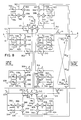
- FIG. 10 is an illustration like FIG. 8 and shows an embodiment of the present invention, and like reference numerals are used where appropriate to facilitate understanding.
- Multi-channel active acoustic attenuation system 450 attenuates one or more correlated input acoustic waves as shown at input noise 452. Correlated means periodic, band-limited, or otherwise having some predictability.
- the system includes one or more output transducers, such as canceling loudspeakers 14, 210, introducing one or more respective canceling acoustic waves to attenuate the input acoustic wave and yield an attenuated output acoustic wave.
- This system includes one or more error transducers, such as error microphones 16, 214, sensing the output acoustic wave and providing respective error signals e 1 , e 2 .
- Each channel model has an error input from each of the error transducers 16, 214, etc.
- the system includes the above noted plurality of error paths, including a first set of error paths SE 11 and SE 21 between first output transducer 14 and each of error transducers 16 and 214, a second set of error paths SE 12 and SE 22 between second output transducer 210 and each of error transducers 16 and 214, and so on.
- Each channel model is updated for each error path of a given set from a given output transducer, to be described.
- Each channel model has a first set of one or more model inputs from respective error transducers, and a second set of model inputs from remaining model outputs of the remaining channel models.
- first channel model A 11 , B 11 has a first set of model inputs A 11 x ' / 1 and A 12 x ' / 2 summed at summer 308.
- Input x ' / 1 is provided by the output of summer 454 which has inputs from error path model 362, error path model 402, and error transducer 16.
- Input x ' / 2 is provided by the output of summer 456, which has inputs from error path model 404, error path model 364, and error transducer 214.
- First channel model A 11 , B 11 has a second set of model inputs B 11 y 1 and B 12 y 2 summed at summer 318.
- Second channel model A 22 , B 22 has a first set of model inputs A 22 x ' / 2 and A 21 x ' / 1 summed at summer 304.
- Second channel model A 22 , B 22 has a second set of model inputs B 22 y 2 and B 21 y 1 summed at summer 313.
- Each channel model has first and second algorithm means, A and B, respectively, providing respective direct and recursive transfer functions and each having an error input from each of the error transducers.
- the first channel model thus has a first algorithm filter A 11 at 12 having an input from input signal x ' / 1, a plurality of error inputs 320, 322, one for each of the error transducers 16, 214 and receiving respective error signals e 1 , e 2 therefrom, and an output supplied to summer 308.
- the first channel model includes a second algorithm filter B 11 at 22 having an input from correction signal y 1 from output 312 of the first channel model to the first output transducer 14, a plurality of error inputs 324, 326, one for each of the error transducers 16, 214 and receiving respective error signals e 1 , e 2 therefrom, and an output supplied to summer 318.
- Summers 308 and 318 may be separate or joint and receive the outputs of algorithm filters A 11 and B 11 , and have an output providing correction signal y 1 from model output 312 to the first output transducer 14.
- the first channel model has a third algorithm filter A 12 at 306 having an input from input signal x ' / 2, a plurality of error inputs 328, 330, one for each of the error transducers 16, 214 and receiving respective error signals e 1 , e 2 therefrom, and an output summed at summer 308.
- the second channel model has a first algorithm filter A 22 at 216 having an input from input signal x ' / 2, a plurality of error inputs 336, 338, one for each of the error transducers 16, 214 and receiving respective error signals e 1 , e 2 therefrom, and an output supplied to summer 304.
- the second channel model has a second algorithm filter B 22 at 218 having an input from correction signal y 2 from output 316 of the second channel model to the second output transducer 210, a plurality of error inputs 340, 342, one for each of the error transducers 16, 214 and receiving respective error signals e 1 , e 2 therefrom, and an output supplied to summer 313.
- Summers 304 and 313 may be joint or separate and have inputs from the outputs of the algorithm filters 216 and 218, and an output providing correction signal y 2 from output 316 of the second channel model to the second output transducer 210.
- the second channel model includes a third algorithm filter A 21 at 302 having an input from input signal x ' / 1, a plurality of error inputs 344, 346, one for each of the error transducers 16, 214 and receiving respective error signals e 1 , e 2 therefrom, and an output summed at summer 304.
- Algorithm filter A 11 at 12 of the first channel model includes a set of error path models 352, 354 of respective error paths SE 11 , SE 21 , which are the error paths between first output transducer 14 and each of error transducers 16 and 214.
- the error path models are preferably provided using a random noise source as shown at 140 in FIG. 19 of U.S. Patent 4,677,676, with a copy of the respective error path model provided at 352, 354, etc., as in U.S. Patent 4,677,676 at 144 in FIG. 19, and for which further reference may be had to the above noted Eriksson article "Development of The Filtered-U Algorithm For Active Noise Control".
- Error path model 354 has an input from input signal x ' / 1 and an output multiplied at multiplier 360 with error signal e 2 from the second error transducer 214 to provide a resultant product which is summed at summing junction 358.
- the output of summing junction 358 provides a weight update to algorithm filter A 11 at 12.
- the second algorithm filter B 11 at 22 of the first channel model includes a set of error path models 362, 364 of respective error paths SE 11 , SE 21 between first output transducer 16 and each of error transducers 16, 214.
- Error path model 362 has an input from correction signal y 1 from output 312 of the first channel model applied to first output transducer 14.
- Error path model 362 has an output multiplied at multiplier 366 with error signal e 1 from first error transducer 16 to provide a resultant product which is summed at summing junction 368.
- Error path model 364 has an input from correction signal y 1 from output 312 of the first channel model applied to the first output transducer 14.
- Error path model 364 has an output multiplied at multiplier 370 with error signal e 2 from second error transducer 214 to provide a resultant product which is summed at summing junction 368.
- the output of summing junction 368 provides a weight update to algorithm filter B 11 at 22.
- the third algorithm filter A 12 at 306 of the first channel model includes a set of error path models 372, 374 of respective error paths SE 11 , SE 21 between first output transducer 14 and each of error transducers 16, 214.
- Error path model 372 has an input from input signal x ' / 2 and an output multiplied at multiplier 376 with error signal e 1 from first error transducer 16 to provide a resultant product which is summed at summing junction 378.
- Error path model 374 has an input from input signal x ' / 2 and an output multiplied at multiplier 380 with error signal e 2 from second error transducer 214 to provide a resultant product which is summed at summing junction 378.
- the output of summing junction 378 provides a weight update to algorithm filter A 12 at 306.
- the fourth algorithm filter B 12 at 314 of the first channel model includes a set of error path models 382, 384 of respective error paths SE 11 , SE 21 between first output transducer 14 and each of error transducers 16, 214.
- Error path model 382 has an input from correction signal y 2 from output 316 of the second channel model applied to second output transducer 210.
- Error path model 382 has an output multiplied at multiplier 386 with error signal e 1 from first error transducer 16 to provide a resultant product which is summed at summing junction 388.
- Error path model 384 has an input from correction signal y 2 from output 316 of the second channel model applied to the second output transducer 210.
- Error path model 384 has an output multiplied at multiplier 390 with error signal e 2 from second error transducer 214 to provide a resultant product which is summed at summing junction 388.
- the output of summing junction 388 provides a weight update to algorithm filter B 12 at 314.
- the first algorithm filter A 22 at 216 of the second channel model includes a set of error path models 392, 394 of respective error paths SE 12 , SE 22 between second output transducer 210 and each of error transducers 16, 214.
- Error path model 392 has an input from input signal x ' / 2 and an output multiplied at multiplier 396 with error signal e 1 from first error transducer 16 to provide a resultant product which is summed at summing junction 398.
- Error path model 394 has an input from input signal x ' / 2 and an output multiplied at multiplier 400 with error signal e 2 from second error transducer 214 to provide a resultant product which is summed at summing junction 398.
- the output of summing junction 398 provides a weight update to algorithm filter A 22 at 216.
- the second algorithm filter B 22 at 218 of the second channel model includes a set of error path models 402, 404 of respective error paths SE 12 , SE 22 between second output transducer 210 and each of error transducers 16, 214.
- Error path model 402 has an input from correction signal y 2 from output 316 of the second channel model applied to the second output transducer 210.
- Error path model 402 has an output multiplied at multiplier 406 with error signal e 1 from first error transducer 16 to provide a resultant product which is summed at summing junction 408.
- Error path model 404 has an input from correction signal y 2 from output 316 of the second channel model applied to the second output transducer 210.
- Error path model 404 has an output multiplied with error signal e 2 at multiplier 410 to provide a resultant product which is summed at summing junction 408.
- the output of summing junction 408 provides a weight update to algorithm filter B 22 at 218.
- the third algorithm filter A 21 at 302 of the second channel model includes a set of error path models 412, 414 of respective error paths SE 12 , SE 22 between second output transducer 210 and each of error transducers 16, 214.
- Error path model 412 has an input from input signal x ' / 1 and an output multiplied at multiplier 416 with error signal e 1 to provide a resultant product which is summed at summing junction 418.
- Error path model 414 has an input from input signal x ' / 1 and an output multiplied at multiplier 420 with error signal e 2 from second error transducer 214 to provide a resultant product which is summed at summing junction 418.
- the output of summing junction 418 provides a weight update to algorithm filter A 21 at 302.
- the fourth algorithm filter B 21 at 310 of the second channel model includes a set of error path models 422, 424 of respective error paths SE 12 , SE 22 between second output transducer 210 and each of error transducers 16, 214.
- Error path model 422 has an input from correction signal y 1 from output 312 of the first channel model applied to the first output transducer 14.
- Error path model 422 has an output multiplied at multiplier 426 with error signal e 1 from first error transducer 16 to provide a resultant product which is summed at summing junction 428.
- Error path model 424 has an input from correction signal y 1 from output 312 of the first channel model applied to the first output transducer 14.
- Error path model 424 has an output multiplied at multiplier 430 with error signal e 2 from the second error transducer 214 to provide a resultant product which is summed at summing junction 428.
- the output of summing junction 428 provides a weight update to algorithm filter B 21 at 310.
- the system includes a plurality of adaptive filter channel models, such as models 512, 514, 516, and 518, each preferably provided by a least-mean-square, LMS, filter A 11 , A 12 , A 22 , and A 21 , respectively.
- Model 512 has a model input 520 from error transducer 508.
- Model 512 has an error input 522 from each of error transducers 508 and 510.
- Model 512 has a model output 524 outputting a correction signal to output transducer 504.
- Model 514 has a model input 526 from error transducer 510.
- Model 514 has an error input 528 from each of error transducers 508 and 510.
- Model 514 has a model output 530 outputting a correction signal to output transducer 504.
- Model 516 has a model input 532 from error transducer 510.
- Model 516 has an error input 534 from each of error transducers 508 and 510.
- Model 516 has a model output 536 outputting a correction signal to output transducer 506.
- Model 518 has a model input 538 from error transducer 508.
- Model 518 has an error input 540 from each of error transducers 508 and 510.
- Model 518 has a model output 542 outputting a correction signal to output transducer 506.
- Summer 544 sums the correction signals from models 512 and 514 and provides an output resultant sum y 1 at 546.
- Summer 548 sums the correction signals from models 516 and 518 and provides an output resultant sum y 2 at 550.
- Summer 552 sums the output of summers 544 and 548 and provides an output resultant sum at 554.
- Summer 556 sums the outputs of summers 544 and 548 and provides an output resultant sum at 558.
- Summers 552 and 560 may be separate or common.
- Summer 560 sums the output of summer 552 and the error signal e 1 from error transducer 508 and provides an output resultant sum x 1 at 562 to model input 520 of model 512 and also to model input 538 of model 518.
- Summer 564 sums the output of summer 556 and the error signal e 2 from error transducer 510 and provides an output resultant sum at 566 to model input 532 of model 516 and also to model input 526 of model 514.
- FIG. 11 shows cross-coupling of acoustic paths of the system, including: acoustic path P 1 to the first error transducer 508 from the periodic noise source 502; acoustic path P 2 to the second error transducer 510 from source 502; acoustic path SE 11 to the first error transducer 508 from the first output transducer 504; acoustic path SE 21 to the second error transducer 510 from the first output transducer 504; acoustic path SE 12 to the first error transducer 508 from the second output transducer 506; and acoustic path SE 22 to the second error transducer 510 from the second output transducer 506.
- Model 512 includes a set of error path models 568, 570 of respective error paths SE 11 , SE 21 , which are the error paths between first output transducer 504 and each of error transducers 508 and 510.
- the error path models are preferably provided as above, using a random noise source as shown at 140 in FIG. 19 of U.S. Patent 4,677,676, with a copy of the respective error path model provided at 568, 570, etc., as in U.S. Patent 4,677,676 at 144 in FIG. 19, and for which further reference may be had to the above noted Eriksson article "Development of The Filtered-U Algorithm For Active Noise Control".
- the error path may be modeled without a random noise source as in U.S.
- the error path modeling include modeling of the transfer functions of both the speaker 504 and the acoustic path from such speaker to the error microphones.
- the SE model may include only one of such transfer functions, for example if the other transfer function is relatively constant.
- the SE error path models are eliminated, i.e. replaced by a unity transfer function.
- Error path model 568 has an input 572 from sum x 1 , and an output 574 multiplied at multiplier 576 with error signal e 1 .
- Error path model 570 has an input 578 from sum x 1 , and an output 580 multiplied at multiplier 582 with the error signal e 2 .
- the outputs of multipliers 576 and 582 are summed at summer 584 which provides an output resultant sum to error input 522 of model 512.
- Model 514 includes a set of error path models 586, 588 of respective error paths SE 11 , SE 21 between first output transducer 504 and each of error transducers 508, 510.
- Error path model 586 has an input 590 from sum x 2 , and an output 592 multiplied at multiplier 594 with error signal e 1 .
- Error path model 588 has an input 596 from sum x 2 , and an output 598 multiplied at multiplier 600 with error signal e 2 .
- the outputs of multipliers 594 and 600 are summed at summer 602 which provides an output resultant sum to error input 528 of model 514.
- Model 516 includes a set of error path models 604, 606 of respective error paths SE 22 , SE 12 between second output transducer 506 and each of error transducers 510, 508.
- Error path model 604 has an input 608 from sum x 2 , and an output 610 multiplied at multiplier 612 with error signal e 2 .
- Error path model 606 has an input 614 from sum x 2 , and an output 616 multiplied at multiplier 618 with error signal e 1 .
- the outputs of multipliers 612 and 618 are summed at summer 620 which provides an output resultant sum to error input 534 of model 516.
- Model 518 includes a set of error path models 622, 624 of respective error paths SE 22 , SE 12 between output transducer 506 and each of the error transducers 510, 508.
- Error path model 622 has an input 626 from sum x 1 , and an output 628 multiplied at multiplier 630 with error signal e 2 .
- Error path model 624 has an input 632 from sum x 1 , and an output 634 multiplied at multiplier 636 with error signal e 1 .
- the outputs of multipliers 630 and 636 are summed at summer 638 which provides an output resultant sum to error input 540 of model 518.
- Error path model 640 of error path SE 11 has an input 642 from sum y 1 , and has an output 644 supplied to summer 552.
- Error path model 646 of error path SE 12 has an input 648 from sum y 2 , and has an output 650 supplied to summer 552.
- Error path model 652 of error path SE 22 has an input 654 from sum y 2 , and has an output 656 supplied to summer 556.
- Error path model 658 of error path SE 21 has an input 660 from sum y 1 , and has an output 662 supplied to summer 556.
- the correction signals from models 512 and 514 at respective model outputs 524 and 530 are supplied through summers 544, 552 and 560 to model input 520 of model 512 and also to model input 538 of model 518.
- the correction signals from models 516 and 518 at respective model outputs 536 and 542 are supplied through summers 548, 556 and 564 to model input 532 of model 516 and also to model input 526 of model 514.
- SE error path models 568, 570, 586, 588, 604, 606, 622, 624, 640, 646, 652, 658 are eliminated, i.e. replaced by a unity transfer function.
- the present invention is not limited to a two channel system, but rather may be expanded to any number of channels. It is preferred that each channel have its own output transducer and error transducer, though other combinations are possible.
- the system is applicable to one or more output transducers, one or more error transducers, and a plurality of channel models, and at a minimum includes at least two output transducers and/or two error transducers.
- the system may be used with one correlated noise source or multiple correlated noise sources or one correlated noise generator driving multiple noise sources.
- the system includes a propagation path or environment such as defined by a duct or plant 4, though the environment is not limited thereto and may be a room, a vehicle cab, free space, etc.
- the system has other applications such as vibration control in structures or machines, wherein the error transducers are accelerometers for sensing the respective acoustic waves, and the output transducers are shakers for outputting canceling acoustic waves.
- the system can also be used to control multiple degrees of freedom of a rigid body.
- An exemplary application is active engine mounts in an automobile or truck for damping engine vibration.
- the system is also applicable to complex structures for controlling vibration.
- the system may be used for attenuation of an undesirable elastic wave in an elastic medium, i.e. an acoustic wave propagating in an acoustic medium.
Landscapes
- Physics & Mathematics (AREA)
- Engineering & Computer Science (AREA)
- Acoustics & Sound (AREA)
- Multimedia (AREA)
- Circuit For Audible Band Transducer (AREA)
- Soundproofing, Sound Blocking, And Sound Damping (AREA)
- Filters That Use Time-Delay Elements (AREA)
Claims (28)
- Aktives akustisches Mehrkanal-Dämpfungssystem zum Dämpfen einer korrelierten akustischen Eingangswelle mitaufweist,einem oder mehreren Ausgangswandlern zum Einleiten einer bzw. mehrerer akustischer Auslöschwellen zum Dämpfen der akustischen Eingangswelle und Erzeugen einer gedämpften akustischen Ausgangswelle,einem oder mehreren Fehlerwandlern zum Erfassen der akustischen Ausgangswelle und Erzeugen eines bzw. mehrerer Fehlersignale, undmehreren Adaptivfilter-Kanalmodellen, deren jedeseinen Fehlereingang von dem Fehlerwandler,einen Modellausgang zur Abgabe eines Korrektursignals an den Ausgangswandler, undeinen Modelleingang von dem Fehlerwandler
wobei mindestens eines der Kanalmodelle auch einen Modelleingang vom Ausgang eines weiteren Kanalmodells aufweist. - System nach Anspruch 1 mit mehreren Fehlerwandlern, wobei jedes Kanalmodell einen Modelleingang von einem betreffenden Fehlerwandler aufweist.
- System nach Anspruch 2, wobei jedes Kanalmodell auch einen Fehlereingang von dem jeweiligen Fehlerwandler aufweist.
- System nach Anspruch 2 oder 3, wobei jedes Kanalmodell einen Fehlereingang von mehreren Fehlerwandlern aufweist.
- System nach Anspruch 3, wobei jedes Kanalmodell einen Fehlereingang von jedem der Fehlerwandler aufweist.
- System nach einem der vorhergehenden Ansprüche, wobei das Korrektursignal von jedem Modelleingang auch ein Eingangssignal am Modelleingang jedes weiteren Kanalmodells bildet.
- System nach einem der vorhergehenden Ansprüche mit mehreren Ausgangswandlern, wobei jeder Modell ausgang ein Korrektursignal an einen betreffenden Ausgangswandler abgibt.
- System nach Anspruch 7, wobei das Korrektursignal vom Modellausgang des betreffenden Ausgangswandlers auch ein Eingangssignal desselben Kanalmodells sowie mindestens eines der übrigen Kanalmodelle bildet.
- System nach einem der vorhergehenden Ansprüche mit einem ersten und einem zweiten Fehlerwandler, einem ersten und einem zweiten Kanalmodell, wobei das erste Kanalmodell einen Modelleingang von dem ersten Fehlerwandler, einen Fehlereingang von sowohl dem ersten als auch dem zweiten Fehlerwandler aufweist und einen Modellausgang aufweist, und wobei das zweite Kanalmodell einen Modelleingang von dem zweiten Fehlerwandler, einen Fehlereingang von sowohl dem ersten als auch dem zweiten Fehlerwandler aufweist und einen Modellausgang aufweist, der auf den Modellausgang des ersten Kanalmodells zur Bildung einer Summe aufsummiert wird, die als Fehlersignal an einem der Ausgangswandler liegt.
- System nach einem der Ansprüche 1 bis 8 mit einem ersten und einem zweiten Ausgangswandler, einem ersten und einem zweiten Fehlerwandler und einem ersten und einem zweiten Kanalmodell, wobei das erste Kanalmodell einen Modellausgang zur Abgabe eines Korrektursignals an den ersten Ausgangswandler sowie einen Fehlereingang von dem ersten Fehlerwandler und einen Modelleingang von dem ersten Fehlerwandler sowie von den Modellausgängen des ersten und des zweiten Kanalmodells aufweist, und wobei das zweite Kanalmodell einen Modellausgang zur Abgabe eines Korrektursignals an den zweiten Ausgangswandler, einen Fehlereingang von dem zweiten Fehlerwandler und einen Modelleingang von dem zweiten Fehlerwandler sowie von den Modellausgängen des zweiten und des ersten Kanalmodells aufweist.
- System nach einem der Ansprüche 1 bis 8 miteinem ersten und einem zweiten Ausgangswandler zum Einleiten einer ersten und einer zweiten akustischen Auslöschwelle zum Dämpfen der akustischen Eingangswelle und Erzeugung einer gedämpften akustischen Ausgangswelle,einem ersten und einem zweiten Fehlerwandler zur Erfassung der akustischen Ausgangswelle und Erzeugung eines ersten und eines zweiten Fehlersingals,einem ersten Adaptivfilter-Kanalmodell mit einem Modelleingang von dem ersten Fehlerwandler, einem Fehlereingang von sowohl dem ersten als auch dem zweiten Fehlerwandler und einem Modellausgang zur Abgabe eines Korrektursignals an den ersten Ausgangswandler,einem zweiten Adaptivfilter-Kanalmodell mit einem Modelleingang von dem zweiten Fehlerwandler, einem Fehlereingang von sowohl dem ersten als auch dem zweiten Fehlerwandler und einem Modellausgang zur Abgabe eines Korrektursignals an den ersten Ausgangswandler,einem dritten Adaptivfilter-Kanalmodell mit einem Modelleingang von dem zweiten Fehlerwandler, einem Fehlereingang von sowohl dem ersten als auch dem zweiten Fehlerwandler und einem Modellausgang zur Abgabe eines Korrektursignals an den zweiten Ausgangswandler, undeinem vierten Adaptivflter-Kanalmodell mit einem Modelleingang von dem ersten Fehlerwandler, einem Fehlerausgang von sowohl dem ersten als auch dem zweiten Fehlerwandler und einem Modellausgang zur Abgabe eines Korrektursignals an den zweiten Ausgangswandler.
- System nach Anspruch 11, wobei die Korrektursignale des ersten, des zweiten, des dritten und des vierten Kanalmodells an jedem der Modelleingänge des ersten, des zweiten, des dritten und des vierten Kanalmodells liegen.
- System nach Anspruch 11 oder 12 miteinem ersten Summierglied zum Aufsummieren der Korrektursignale des ersten und des zweiten Kanalmodells unter Bildung einer Ausgangssumme,einem zweiten Summierglied zum Aufsummieren der Korrektursignale des dritten und des vierten Kanalmodells unter Bildung einer Ausgangssumme,einem dritten Summierglied zum Aufsummieren der Ausgangssignale des ersten und des zweiten Summiergliedes unter Bildung einer Ausgangssumme,einem vierten Summierglied zum Aufsummieren der Ausgangssignale des ersten und des zweiten Summiergliedes unter Bildung einer Ausgangssumme,einem fünften Summierglied zum Aufsummieren der Ausgangssignale des dritten Summiergliedes und des ersten Fehlerwandlers unter Bildung einer Ausgangssumme an den Modelleingängne des ersten und des vierten Kanalmodells, undeinem sechsten Summierglied zum Aufsummieren der Ausgangssignale des vierten Summiergliedes und des zweiten Fehlerwandlers unter Bildung einer Ausgangssumme an den Modelleingängen des dritten Kanalmodells und des zweiten Kanalmodells.
- System nach Anspruch 13, wobeisowie ferner mitdas erste Kanalmodell eine erste Gruppe von Fehlerpfadmodellen von Fehlerpfaden zwischen dem ersten Ausgangswandler und sowohl dem ersten als auch dem zweiten Fehlerwandler aufweist, wobei die erste Gruppe ein erstes Fehlerpfadmodell mit einem Eingang von dem ersten Fehlerwandler und einem Ausgang, der in einem ersten Multiplizierglied mit dem Ausgang des ersten Fehlerwandlers multipliziert wird, sowie ein zweites Fehlerpfadmodell mit einem Eingang von dem ersten Fehlerwandler und einem Ausgang, der in einem zweiten Multiplizierglied mit dem Ausgang des zweiten Fehlerwandlers multipliziert wird, aufweist, wobei die Ausgangssignale des ersten und des zweiten Multipliziergliedes in einem dritten Summierglied unter Bildung einer am Fehlereingang des ersten Kanalmodells liegenden Summe aufsummiert werden,das zweite Kanalmodell eine zweite Gruppe von Fehlerpfadmodellen von Fehlerpfaden zwischen dem ersten Ausgangswandler und sowohl dem ersten als auch dem zweiten Fehlerwandler aufweist, wobei die zweite Gruppe ein drittes Fehlerpfadmodell mit einem Eingang von dem zweiten Fehlerwandler und einem Ausgang, der in einem dritten Multiplizierglied mit dem Ausgang des ersten Fehlerwandlers multipliziert wird, sowie ein viertes Fehlerpfadmodell mit einem Eingang von dem ersten Fehlerwandler und einem Ausgang, der in einem vierten Multiplizierglied mit dem Ausgang des zweiten Fehlerwandlers multipliziert wird, aufweist, wobei die Ausgangssignale des dritten und des vierten Multipliziergliedes in einem achten Summierglied unter Bildung einer am Fehlereingang des zweiten Kanalmodells liegenden Summe aufsummiert werden,das dritte Kanalmodell eine dritte Gruppe von Fehlerpfadmodellen von Fehlerpfaden zwischen dem zweiten Ausgangswandler und sowohl dem ersten als auch dem zweiten Fehlerwandler aufweist, wobei die dritte Gruppe ein fünftes Fehlerpfadmodell mit einem Eingang von dem zweiten Fehlerwandler und einem Ausgang, der in einem fünften Multiplizierglied mit dem Ausgang des zweiten Fehlerwandlers multipliziert wird, sowie ein sechstes Fehlerpfadmodell mit einem Eingang von dem sechsten Fehlerwandler und einem Ausgang, der in einem sechsten Multiplizierglied mit dem Ausgang des ersten Fehlerwandlers multipliziert wird, aufweist, wobei die Ausgangssignale des fünften und des sechsten Multipliziergliedes in einem neunten Summierglied unter Bildung einer am Fehlereingang des dritten Kanalmodells liegenden Summe aufsummiert werden,das vierte Kanalmodell eine vierte Gruppe von Fehlerpfadmodellen von Fehlerpfaden zwischen dem zweiten Ausgangswandler und sowohl dem ersten als auch dem zweiten Fehlerwandler aufweist, wobei die vierte Gruppe ein siebtes Fehlerpfadmodell mit einem Eingang von dem ersten Fehlerwandler und einem Ausgang, der in einem siebten Multiplizierglied mit dem Ausgang des zweiten Fehlerwandlers multipliziert wird, sowie ein zweites Fehlerpfadmodell mit einem Eingang von dem ersten Fehlerwandler und einem Ausgang, der in einem zweiten Multiplizierglied mit dem Ausgang des ersten Fehlerwandlers multipliziert wird, aufweist, wobei die Ausgangssignale des siebten und des achten Multipliziergliedes in einem dritten Summierglied unter Bildung einer am Fehlereingang des vierten Kanalmodells liegenden Summe aufsummiert werden,einem neunten Fehlerpfadmodell, das ein Eingangssignal vom Ausgang des ersten Summiergliedes aufweist und ein an dem dritten Summierglied liegendes Ausgangssignal aufweist,einem zehnten Fehlerpfadmodell, das ein Eingangssignal vom Ausgang des zweiten Summiergliedes aufweist und ein an dem dritten Summierglied liegendes Ausgangssignal aufweist,einem elften Fehlerpfadmodell, das ein Eingangssignal vom Ausgang des zweiten Summiergliedes aufweist und ein an dem vierten Summierglied liegendes Ausgangssignal aufweist,einem zwölften Fehlerpfadmodell, das ein Eingangssignal vom Ausgang des ersten Summiergliedes aufweist und ein an dem vierten Summierglied liegendes Ausgangssignal aufweist.
- Aktives akustisches Mehrkanal-Dämpfungsverfahren zum Dämpfen einer korrelierten akustischen Eingangswelle, wobeiein oder mehrere akustische Auslöschwellen von einem bzw. mehreren Ausgangswandlern zum Dämpfen der akustischen Eingangswelle und Erzeugung einer gedämpften akustischen Ausgangswelle eingeleitet werden,die akustische Ausgangswelle an einem oder mehreren Fehlerwandlern erfaßt wird und ein bzw. mehrere Fehlersignale erzeugt werden,mehrere Adaptivfilter-Kanalmodelle vorgesehen werden, deren jedes mit einem Modelleingang von dem Fehlerwandler, einem Fehlereingang von dem Fehlerwandler und einem Modellausgang zur Abgabe eines Korrektursignals an einen der Ausgangswandler zum Einleiten der akustischen Auslöschwelle und ferner ein oder mehrere der Kanalmodelle mit einem Modelleingang vom Modellausgang eines weiteren Kanalmodells beaufschlagt werden.
- Verfahren nach Anspruch 15, wobei mehrere Fehlerwandler vorgesehen werden und jedes Kanalmodell mit einem Modelleingang von einem betreffenden Fehlerwandler beaufschlagt wird.
- Verfahren nach Anspruch 16, wobei jedes Kanalmodell mit einem Fehlereingang von dem jeweiligen Fehlerwandler beaufschlagt wird.
- Verfahren nach Anspruch 16 oder 17, wobei jedes Kanalmodell mit einem Fehlereingang von mehreren Fehlerwandlern beaufschlagt wird.
- Verfahren nach Anspruch 18, wobei jedes Kanalmodell mit einem Fehlereingang von jedem der Fehlerwandler beaufschlagt wird.
- Verfahren nach einem der Ansprüche 15 bis 19, wobei die Korrektursignale von jedem Fehlermodell als Eingangssignal jedes weiteren Kanalmodells vorgesehen wird.
- Verfahren nach einem der Ansprüche 15 bis 20, wobei mehrere Ausgangswandler vorgesehen werden und ein Korrektursignal von jedem Modelleingang eines jeweiligen Ausgangswandlers vorgesehen wird.
- Verfahren nach Anspruch 21, wobei das Korrektursignal vom Modellausgang des jeweiligen Ausgangswandlers ausgegeben und dieses Korrektursignal dem gleichen Kanalmodell sowie mindestens einem weiteren Kanalmodell zugeführt wird.
- Verfahren nach einem der Ansprüche 15 bis 22, wobei ein erster und ein zweiter Fehlerwandler sowie ein erstes und ein zweites Kanalmodell vorgesehen werden, das erste Kanalmodell mit einem Modelleingang von dem ersten Fehlerwandler, einem Fehlereingang von sowohl dem ersten als auch dem zweiten Fehlerwandler und mit einem Modellausgang versehen wird, das zweite Kanalmodell mit einem Modelleingang von dem zweiten Fehlerwandler, mit einem Fehlereingang von sowohl dem ersten als auch dem zweiten Fehlerwandler und mit einem Modell ausgang versehen wird, und der Modellausgang des zweiten Kanalmodells auf den des ersten Kanalmodells aufsummiert und die so gebildete Summe als Korrektursignal einem entsprechenden Ausgangswandler zugeführt wird.
- Verfahren nach einem der Ansprüche 15 bis 22, wobei ein erster und ein zweiter Ausgangswandler, ein erster und ein zweiter Fehlerwandler und ein erstes und ein zweites Kanalmodell vorgesehen werden, das erste Kanalmodell mit einem Modellausgang, der ein Korrektursignal an den ersten Ausgangswandler abgibt, einem Fehlereingang von dem ersten Fehlerwandler und einem Modelleingang von dem ersten Fehlerwandler sowie von den Modellausgängne des ersten und des zweiten Kanalmodells versehen wird, das zweite Kanalmodell mit einem Modellausgang, der ein Korrektursignal an den zweiten Ausgangswandler abgibt, einem Fehlereingang von dem zweiten Fehlerwandler und einem Modelleingang von dem zweiten Fehlerwandler sowie von den Modellausgängen des zweiten und des ersten Kanalmodells versehen wird.
- Verfahren nach einem der Ansprüche 15 bis 22, wobeieine erste und eine zweite akustische Auslöschwelle von dem ersten und dem zweiten Ausgangswandler eingeleitet wird, um die akustische Eingangswelle zu dämpfen und eine gedämpfte akustische Ausgangswelle zu erzeugen,die akustische Ausgangswelle mit dem ersten und dem zweiten Fehlerwandler unter Erzeugung eines ersten und eines zweiten Fehlersignals erfaßt wird,ein erstes Adaptivfilter-Kanalmodell vorgesehen wird, das mit einem Modelleingang von dem ersten Fehlerwandler, einem Fehlereingang von sowohl dem ersten als auch dem zweiten Fehlerwandler sowie einem Modellausgang versehen wird, der ein Korrektursignal an den ersten Ausgangswandler abgibt,ein zweites Adaptivfilter-Kanalmodell vorgesehen wird, das mit einem Modelleingang von dem zweiten Fehlerwandler, einem Fehlereingang von sowohl dem ersten als auch dem zweiten Fehlerwandler sowie einem Modellausgang versehen wird, der ein Korrektursignal an den ersten Ausgangswandler abgibt,ein drittes Adaptivfilter-Kanalmodell vorgesehen wird, das mit einem Modelleingang von dem zweiten Fehlerwandler, einem Fehlereingang von sowohl dem ersten als auch dem zweiten Fehlerwandler sowie einem Modellausgang versehen wird, der ein Korrektursignal an den zweiten Ausgangswandler abgibt, undein viertes Adaptivfilter-Kanalmodell vorgesehen wird, das mit einem Modelleingang von dem ersten Fehlerwandler, einem Fehlereingang von sowohl dem ersten als auch dem zweiten Fehlerwandler sowie einem Modellausgang versehen wird, der ein Korrektursignal an den zweiten Ausgangswandler abgibt.
- Verfahren nach Anspruch 25, wobei die Korrektursignale von dem ersten, dem zweiten, dem dritten und dem vierten Kanalmodell jedem der Modelleingänge des ersten, des zweiten, des dritten und des vierten Kanalmodells zugeführt werden.
- Verfahren nach Anspruch 25 oder 26, wobeidie Korrektursignale von dem ersten und dem zweiten Kanalmodell in einem ersten Summierglied unter Bildung einer Ausgangssumme aufsummiert werden,die Korrektursignale von dem dritten und dem vierten Kanalmodell in einem zweiten Summierglied unter Bildung einer Ausgangssumme aufsummiert werden,die Ausgänge des ersten und des zweiten Summiergliedes in einem dritten Summierglied unter Bildung einer Ausgangssumme aufsummiert werden,die Ausgänge des ersten und des zweiten Summiergliedes in einem vierten Summierglied unter Bildung einer Ausgangssumme aufsummiert werden,die Ausgänge des dritten Summiergliedes und des ersten Fehlerwandlers in einem fünften Summierglied unter Bildung einer Ausgangssumme aufsummiert werden, die an den Modelleingängne des ersten und des vierten Kanalmodells liegt, unddie Ausgänge des vierten Summiergliedes und des zweiten Fehlerwandlers in einem sechsten Summierglied unter Bildung einer Ausgangssumme aufsummiert werden, die an den Modelleingängne des dritten und des zweiten Kanalmodells liegt.
- Verfahren nach Anspruch 27, wobeidas erste Kanalmodell mit einer ersten Gruppe von Fehlerpfadmodellen von Fehlerpfaden zwischen dem ersten Ausgangswandler und sowohl dem ersten als auch dem zweiten Fehlerwandler, die erste Gruppe mit einem ersten Fehlerpfadmodell und das erste Fehlerpfadmodell mit einem Eingang von dem ersten Fehlerwandler und einem Ausgang versehen wird, der Ausgang des ersten Fehlerpfadmodells in einem ersten Multiplizierglied mit dem des ersten Fehlerwandlers multipliziert werden, die erste Gruppe mit einem zweiten Fehlerpfadmodell und das zweite Fehlerpfadmodell mit einem Eingang von dem ersten Fehlerwandler und mit einem Ausgang versehen wird, der Ausgang des zweiten Fehlerpfadmodells in einem zweiten Multiplizierglied mit dem des zweiten Fehlerwandlers multipliziert und die Ausgänge des ersten und des zweiten Multipliziergliedes in einem siebten Summierglied unter Bildung einer Ausgangssumme am Fehlereingang des ersten Kanalmodells aufsummiert werden,das zweite Kanalmodell mit einer zweiten Gruppe von Fehlerpfadmodellen von Fehlerpfaden zwischen dem ersten Ausgangswandler und sowohl dem ersten als auch dem zweiten Fehlerwandler, die zweite Gruppe mit einem dritten Fehlerpfadmodell und das dritte Fehlerpfadmodell mit einem Eingang von dem zweiten Fehlerwandler und einem Ausgang versehen wird, der Ausgang des dritten Fehlerpfadmodells in einem dritten Multiplizierglied mit dem des ersten Fehlerwandlers multipliziert werden, die zweite Gruppe mit einem vierten Fehlerpfadmodell und das vierte Fehlerpfadmodell mit einem Eingang von dem zweiten Fehlerwandler und mit einem Ausgang versehen wird, der Ausgang des vierten Fehlerpfadmodells in einem vierten Multiplizierglied mit dem des zweiten Fehlerwandlers multipliziert und die Ausgänge des dritten und des vierten Multipliziergliedes in einem achten Summierglied unter Bildung einer Ausgangssumme am Fehlereingang des zweiten Kanalmodells aufsummiert werden,das dritte Kanalmodell mit einer dritten Gruppe von Fehlerpfadmodellen von Fehlerpfaden zwischen dem zweiten Ausgangswandler und sowohl dem ersten als auch dem zweiten Fehlerwandler, die dritte Gruppe mit einem fünften Fehlerpfadmodell und das fünfte Fehlerpfadmodell mit einem Eingang von dem zweiten Fehlerwandler und einem Ausgang versehen wird, der Ausgang des fünften Fehlerpfadmodells in einem fünften Multiplizierglied mit dem des zweiten Fehlerwandlers multipliziert werden, die dritte Gruppe mit einem sechsten Fehlerpfadmodell und das sechste Fehlerpfadmodell mit einem Eingang von dem zweiten Fehlerwandler und mit einem Ausgang versehen wird, der Ausgang des sechsten Fehlerpfadmodells in einem sechsten Multiplizierglied mit dem des ersten Fehlerwandlers multipliziert und die Ausgänge des fünften und des sechsten Multipliziergliedes in einem neunten Summierglied unter Bildung einer Ausgangssumme am Fehlereingang des dritten Kanalmodells aufsummiert werden,das vierte Kanalmodell mit einer vierten Gruppe von Fehlerpfadmodellen von Fehlerpfaden zwischen dem zweiten Ausgangswandler und sowohl dem ersten als auch dem zweiten Fehlerwandler, die vierte Gruppe mit einem siebten Fehlerpfadmodell und das siebte Fehlerpfadmodell mit einem Eingang von dem siebten Fehlerwandler und einem Ausgang versehen wird, der Ausgang des siebten Fehlerpfadmodells in einem siebten Multiplizierglied mit dem des zweiten Fehlerwandlers multipliziert werden, die vierte Gruppe mit einem achten Fehlerpfadmodell und das achte Fehlerpfadmodell mit einem Eingang von dem ersten Fehlerwandler und mit einem Ausgang versehen wird, der Ausgang des achten Fehlerpfadmodells in einem achten Multiplizierglied mit dem des ersten Fehlerwandlers multipliziert und die Ausgänge des siebten und des achten Multipliziergliedes unter Bildung einer Ausgangssumme am Fehlereingang des vierten Kanalmodells aufsummiert werden,ein neuntes Fehlerpfadmodell mit einem Eingang und einem Ausgang vorgesehen wird, der Ausgang des ersten Summiergliedes dem Eingang des neunten Fehlerpfadmodells und der Ausgang des neunten Fehlerpfadmodells dem dritten Summierglied zugeführt wird,ein zehntes Fehlerpfadmodell mit einem Eingang und einem Ausgang vorgesehen wird, der Ausgang des zweiten Summiergliedes dem Eingang des zehnten Fehlerpfadmodells und der Ausgang des zehnten Fehlerpfadmodells dem dritten Summierglied zugeführt wird,ein elftes Fehlerpfadmodell mit einem Eingang und einem Ausgang vorgesehen wird, der Ausgang des zweiten Summiergliedes dem Eingang des elften Fehlerpfadmodells und der Ausgang des elften Fehlerpfadmodells dem vierten Summierglied zugeführt wird, undein zwölftes Fehlerpfadmodell mit einem Eingang und einem Ausgang vorgesehen wird, der Ausgang des ersten Summiergliedes dem Eingang des zwölften Fehlerpfadmodells und der Ausgang des zwölften Fehlerpfadmodells dem vierten Summierglied zugeführt wird.
Applications Claiming Priority (2)
| Application Number | Priority Date | Filing Date | Title |
|---|---|---|---|
| US07/794,115 US5216722A (en) | 1991-11-15 | 1991-11-15 | Multi-channel active attenuation system with error signal inputs |
| US794115 | 1991-11-15 |
Publications (3)
| Publication Number | Publication Date |
|---|---|
| EP0542457A2 EP0542457A2 (de) | 1993-05-19 |
| EP0542457A3 EP0542457A3 (en) | 1994-06-29 |
| EP0542457B1 true EP0542457B1 (de) | 1999-04-07 |
Family
ID=25161758
Family Applications (1)
| Application Number | Title | Priority Date | Filing Date |
|---|---|---|---|
| EP92309995A Expired - Lifetime EP0542457B1 (de) | 1991-11-15 | 1992-10-30 | Vielkanal-aktive Dampfungsanordnung mit Eingabe von Fehlersignalen |
Country Status (4)
| Country | Link |
|---|---|
| US (1) | US5216722A (de) |
| EP (1) | EP0542457B1 (de) |
| CA (1) | CA2082890C (de) |
| DE (1) | DE69228854T2 (de) |
Families Citing this family (41)
| Publication number | Priority date | Publication date | Assignee | Title |
|---|---|---|---|---|
| US5457749A (en) * | 1990-04-09 | 1995-10-10 | Noise Cancellation Technologies, Inc. | Electronic muffler |
| EP0557071B1 (de) * | 1992-02-19 | 1999-05-12 | Hitachi, Ltd. | Aktives Lärmminderungsgerät für einen dreidimensionalen Raum |
| JP2882170B2 (ja) * | 1992-03-19 | 1999-04-12 | 日産自動車株式会社 | 能動型騒音制御装置 |
| FR2699205B1 (fr) * | 1992-12-11 | 1995-03-10 | Decaux Jean Claude | Perfectionnements aux procédés et dispositifs pour protéger des bruits extérieurs un volume donné, de préférence disposé à l'intérieur d'un local. |
| US5420932A (en) * | 1993-08-23 | 1995-05-30 | Digisonix, Inc. | Active acoustic attenuation system that decouples wave modes propagating in a waveguide |
| US5586189A (en) * | 1993-12-14 | 1996-12-17 | Digisonix, Inc. | Active adaptive control system with spectral leak |
| CA2148962C (en) * | 1994-05-23 | 2000-03-28 | Douglas G. Pedersen | Coherence optimized active adaptive control system |
| US5551650A (en) * | 1994-06-16 | 1996-09-03 | Lord Corporation | Active mounts for aircraft engines |
| US5627896A (en) * | 1994-06-18 | 1997-05-06 | Lord Corporation | Active control of noise and vibration |
| US5586190A (en) * | 1994-06-23 | 1996-12-17 | Digisonix, Inc. | Active adaptive control system with weight update selective leakage |
| US5557682A (en) * | 1994-07-12 | 1996-09-17 | Digisonix | Multi-filter-set active adaptive control system |
| US5590205A (en) * | 1994-08-25 | 1996-12-31 | Digisonix, Inc. | Adaptive control system with a corrected-phase filtered error update |
| US5621803A (en) * | 1994-09-02 | 1997-04-15 | Digisonix, Inc. | Active attenuation system with on-line modeling of feedback path |
| WO1996012269A1 (en) * | 1994-10-13 | 1996-04-25 | The Boeing Company | Jet engine fan noise reduction system utilizing electro pneumatic transducers |
| US5745580A (en) * | 1994-11-04 | 1998-04-28 | Lord Corporation | Reduction of computational burden of adaptively updating control filter(s) in active systems |
| US5570425A (en) * | 1994-11-07 | 1996-10-29 | Digisonix, Inc. | Transducer daisy chain |
| US5561598A (en) * | 1994-11-16 | 1996-10-01 | Digisonix, Inc. | Adaptive control system with selectively constrained ouput and adaptation |
| US5754662A (en) * | 1994-11-30 | 1998-05-19 | Lord Corporation | Frequency-focused actuators for active vibrational energy control systems |
| US5526292A (en) * | 1994-11-30 | 1996-06-11 | Lord Corporation | Broadband noise and vibration reduction |
| US5602928A (en) * | 1995-01-05 | 1997-02-11 | Digisonix, Inc. | Multi-channel communication system |
| US5664019A (en) * | 1995-02-08 | 1997-09-02 | Interval Research Corporation | Systems for feedback cancellation in an audio interface garment |
| KR19990028737A (ko) * | 1995-07-05 | 1999-04-15 | 알. 피. 울프 | 도관내고차원모드의활성소음제어방법및장치ㅡㅁ제어방법및장치 |
| US5715320A (en) * | 1995-08-21 | 1998-02-03 | Digisonix, Inc. | Active adaptive selective control system |
| US5699437A (en) * | 1995-08-29 | 1997-12-16 | United Technologies Corporation | Active noise control system using phased-array sensors |
| US5710822A (en) | 1995-11-07 | 1998-01-20 | Digisonix, Inc. | Frequency selective active adaptive control system |
| US5706344A (en) * | 1996-03-29 | 1998-01-06 | Digisonix, Inc. | Acoustic echo cancellation in an integrated audio and telecommunication system |
| CA2179794A1 (en) * | 1996-06-24 | 1997-12-25 | Radamis Botros | Invisible acoustic screen for open-plan offices and the like |
| US5930371A (en) * | 1997-01-07 | 1999-07-27 | Nelson Industries, Inc. | Tunable acoustic system |
| US6295363B1 (en) | 1997-03-20 | 2001-09-25 | Digisonix, Inc. | Adaptive passive acoustic attenuation system |
| US5978489A (en) * | 1997-05-05 | 1999-11-02 | Oregon Graduate Institute Of Science And Technology | Multi-actuator system for active sound and vibration cancellation |
| US6496581B1 (en) | 1997-09-11 | 2002-12-17 | Digisonix, Inc. | Coupled acoustic echo cancellation system |
| ATE248497T1 (de) * | 1999-12-09 | 2003-09-15 | Frederick Johannes Bruwer | Sprachsverteilungssystem |
| JP4409755B2 (ja) * | 2000-12-15 | 2010-02-03 | パナソニック株式会社 | 能動騒音制御装置 |
| US6549629B2 (en) | 2001-02-21 | 2003-04-15 | Digisonix Llc | DVE system with normalized selection |
| US20060039569A1 (en) * | 2004-08-19 | 2006-02-23 | Antaki Patrick R | Noise canceling toilet |
| WO2008090544A2 (en) * | 2007-01-22 | 2008-07-31 | Silentium Ltd. | Quiet fan incorporating active noise control (anc) |
| US20090136052A1 (en) * | 2007-11-27 | 2009-05-28 | David Clark Company Incorporated | Active Noise Cancellation Using a Predictive Approach |
| ES2834442T3 (es) | 2011-05-11 | 2021-06-17 | Silentium Ltd | Sistema y método de control del ruido |
| US9928824B2 (en) | 2011-05-11 | 2018-03-27 | Silentium Ltd. | Apparatus, system and method of controlling noise within a noise-controlled volume |
| EP3441965A4 (de) * | 2016-04-05 | 2019-05-22 | Sony Corporation | Signalverarbeitungsvorrichtung, signalverarbeitungsverfahren und programm |
| JP7123492B2 (ja) * | 2018-12-26 | 2022-08-23 | アルパイン株式会社 | 能動型騒音制御システム、能動型騒音制御システムの設定方法及びオーディオシステム |
Family Cites Families (9)
| Publication number | Priority date | Publication date | Assignee | Title |
|---|---|---|---|---|
| US4677677A (en) * | 1985-09-19 | 1987-06-30 | Nelson Industries Inc. | Active sound attenuation system with on-line adaptive feedback cancellation |
| US4677676A (en) * | 1986-02-11 | 1987-06-30 | Nelson Industries, Inc. | Active attenuation system with on-line modeling of speaker, error path and feedback pack |
| US4736431A (en) * | 1986-10-23 | 1988-04-05 | Nelson Industries, Inc. | Active attenuation system with increased dynamic range |
| US4815139A (en) * | 1988-03-16 | 1989-03-21 | Nelson Industries, Inc. | Active acoustic attenuation system for higher order mode non-uniform sound field in a duct |
| US4837834A (en) * | 1988-05-04 | 1989-06-06 | Nelson Industries, Inc. | Active acoustic attenuation system with differential filtering |
| US5105377A (en) * | 1990-02-09 | 1992-04-14 | Noise Cancellation Technologies, Inc. | Digital virtual earth active cancellation system |
| US4987598A (en) * | 1990-05-03 | 1991-01-22 | Nelson Industries | Active acoustic attenuation system with overall modeling |
| US5140640A (en) * | 1990-08-14 | 1992-08-18 | The Board Of Trustees Of The University Of Illinois | Noise cancellation system |
| US5216721A (en) * | 1991-04-25 | 1993-06-01 | Nelson Industries, Inc. | Multi-channel active acoustic attenuation system |
-
1991
- 1991-11-15 US US07/794,115 patent/US5216722A/en not_active Expired - Lifetime
-
1992
- 1992-10-30 DE DE69228854T patent/DE69228854T2/de not_active Expired - Lifetime
- 1992-10-30 EP EP92309995A patent/EP0542457B1/de not_active Expired - Lifetime
- 1992-11-13 CA CA002082890A patent/CA2082890C/en not_active Expired - Fee Related
Also Published As
| Publication number | Publication date |
|---|---|
| CA2082890C (en) | 1998-07-14 |
| US5216722A (en) | 1993-06-01 |
| DE69228854D1 (de) | 1999-05-12 |
| EP0542457A3 (en) | 1994-06-29 |
| CA2082890A1 (en) | 1993-05-16 |
| EP0542457A2 (de) | 1993-05-19 |
| DE69228854T2 (de) | 2000-01-05 |
Similar Documents
| Publication | Publication Date | Title |
|---|---|---|
| EP0542457B1 (de) | Vielkanal-aktive Dampfungsanordnung mit Eingabe von Fehlersignalen | |
| EP0510864B1 (de) | Mehrkanalige aktive Schalldämpfungsanordnung | |
| EP0455479B1 (de) | Aktives akustisches Dämpfungssystem mit Gesamtmodellierung | |
| US5206911A (en) | Correlated active attenuation system with error and correction signal input | |
| US5386477A (en) | Active acoustic control system matching model reference | |
| EP0333461B1 (de) | Aktive Schalldämpfungsanordnung für ein nichtuniformes Schallfeld höherer Ordnung in einem Rohr | |
| EP0581566B1 (de) | Aktive akustische Dämfungsanordnung und Spektrumformung | |
| EP0581565B1 (de) | Aktive akustische Dämpfungsanordnung mit Leistungsbegrenzung | |
| US5425105A (en) | Multiple adaptive filter active noise canceller | |
| US5602929A (en) | Fast adapting control system and method | |
| US5621803A (en) | Active attenuation system with on-line modeling of feedback path | |
| US5557682A (en) | Multi-filter-set active adaptive control system | |
| EP0661807B1 (de) | Aktives adaptives Regulierungssystem mit spektralem Lecksignal | |
| Elliott | Active control of structure-borne noise | |
| US5420932A (en) | Active acoustic attenuation system that decouples wave modes propagating in a waveguide | |
| US6195442B1 (en) | Passive vibroacoustic attenuator for structural acoustic control | |
| US5390255A (en) | Active acoustic attenuation system with error and model copy input | |
| Hansen | Does active noise control have a future | |
| JP3505724B2 (ja) | 開口部放射音用電子消音装置 |
Legal Events
| Date | Code | Title | Description |
|---|---|---|---|
| PUAI | Public reference made under article 153(3) epc to a published international application that has entered the european phase |
Free format text: ORIGINAL CODE: 0009012 |
|
| AK | Designated contracting states |
Kind code of ref document: A2 Designated state(s): DE FR GB IT |
|
| PUAL | Search report despatched |
Free format text: ORIGINAL CODE: 0009013 |
|
| AK | Designated contracting states |
Kind code of ref document: A3 Designated state(s): DE FR GB IT |
|
| 17P | Request for examination filed |
Effective date: 19941129 |
|
| 17Q | First examination report despatched |
Effective date: 19970827 |
|
| GRAG | Despatch of communication of intention to grant |
Free format text: ORIGINAL CODE: EPIDOS AGRA |
|
| GRAG | Despatch of communication of intention to grant |
Free format text: ORIGINAL CODE: EPIDOS AGRA |
|
| GRAG | Despatch of communication of intention to grant |
Free format text: ORIGINAL CODE: EPIDOS AGRA |
|
| GRAH | Despatch of communication of intention to grant a patent |
Free format text: ORIGINAL CODE: EPIDOS IGRA |
|
| GRAH | Despatch of communication of intention to grant a patent |
Free format text: ORIGINAL CODE: EPIDOS IGRA |
|
| GRAA | (expected) grant |
Free format text: ORIGINAL CODE: 0009210 |
|
| AK | Designated contracting states |
Kind code of ref document: B1 Designated state(s): DE FR GB IT |
|
| PG25 | Lapsed in a contracting state [announced via postgrant information from national office to epo] |
Ref country code: IT Free format text: LAPSE BECAUSE OF FAILURE TO SUBMIT A TRANSLATION OF THE DESCRIPTION OR TO PAY THE FEE WITHIN THE PRE;WARNING: LAPSES OF ITALIAN PATENTS WITH EFFECTIVE DATE BEFORE 2007 MAY HAVE OCCURRED AT ANY TIME BEFORE 2007. THE CORRECT EFFECTIVE DATE MAY BE DIFFERENT FROM THE ONE RECORDED.SCRIBED TIME-LIMIT Effective date: 19990407 |
|
| REF | Corresponds to: |
Ref document number: 69228854 Country of ref document: DE Date of ref document: 19990512 |
|
| ET | Fr: translation filed | ||
| PLBE | No opposition filed within time limit |
Free format text: ORIGINAL CODE: 0009261 |
|
| 26N | No opposition filed | ||
| REG | Reference to a national code |
Ref country code: GB Ref legal event code: IF02 |
|
| PGFP | Annual fee paid to national office [announced via postgrant information from national office to epo] |
Ref country code: FR Payment date: 20021002 Year of fee payment: 11 |
|
| PGFP | Annual fee paid to national office [announced via postgrant information from national office to epo] |
Ref country code: GB Payment date: 20031009 Year of fee payment: 12 |
|
| PG25 | Lapsed in a contracting state [announced via postgrant information from national office to epo] |
Ref country code: FR Free format text: LAPSE BECAUSE OF NON-PAYMENT OF DUE FEES Effective date: 20040630 |
|
| REG | Reference to a national code |
Ref country code: FR Ref legal event code: ST |
|
| PG25 | Lapsed in a contracting state [announced via postgrant information from national office to epo] |
Ref country code: GB Free format text: LAPSE BECAUSE OF NON-PAYMENT OF DUE FEES Effective date: 20041030 |
|
| GBPC | Gb: european patent ceased through non-payment of renewal fee |
Effective date: 20041030 |
|
| PGFP | Annual fee paid to national office [announced via postgrant information from national office to epo] |
Ref country code: DE Payment date: 20101130 Year of fee payment: 19 |
|
| REG | Reference to a national code |
Ref country code: DE Ref legal event code: R071 Ref document number: 69228854 Country of ref document: DE |
|
| REG | Reference to a national code |
Ref country code: DE Ref legal event code: R071 Ref document number: 69228854 Country of ref document: DE |