EP0333461B1 - Aktive Schalldämpfungsanordnung für ein nichtuniformes Schallfeld höherer Ordnung in einem Rohr - Google Patents
Aktive Schalldämpfungsanordnung für ein nichtuniformes Schallfeld höherer Ordnung in einem Rohr Download PDFInfo
- Publication number
- EP0333461B1 EP0333461B1 EP89302561A EP89302561A EP0333461B1 EP 0333461 B1 EP0333461 B1 EP 0333461B1 EP 89302561 A EP89302561 A EP 89302561A EP 89302561 A EP89302561 A EP 89302561A EP 0333461 B1 EP0333461 B1 EP 0333461B1
- Authority
- EP
- European Patent Office
- Prior art keywords
- input
- error
- output
- transducers
- models
- Prior art date
- Legal status (The legal status is an assumption and is not a legal conclusion. Google has not performed a legal analysis and makes no representation as to the accuracy of the status listed.)
- Expired - Lifetime
Links
- 230000003044 adaptive effect Effects 0.000 claims abstract description 41
- 238000012937 correction Methods 0.000 claims description 25
- 238000000034 method Methods 0.000 claims description 22
- 238000013459 approach Methods 0.000 claims description 7
- 230000001902 propagating effect Effects 0.000 claims description 5
- 238000012546 transfer Methods 0.000 claims description 4
- 230000003993 interaction Effects 0.000 claims description 3
- 238000012549 training Methods 0.000 claims 7
- 238000000638 solvent extraction Methods 0.000 abstract description 6
- 238000005192 partition Methods 0.000 description 6
- 230000000737 periodic effect Effects 0.000 description 3
- 238000009434 installation Methods 0.000 description 2
- 238000004378 air conditioning Methods 0.000 description 1
- 230000002238 attenuated effect Effects 0.000 description 1
- 230000004323 axial length Effects 0.000 description 1
- 238000005094 computer simulation Methods 0.000 description 1
- 238000011161 development Methods 0.000 description 1
- 230000018109 developmental process Effects 0.000 description 1
- 238000012986 modification Methods 0.000 description 1
- 230000004048 modification Effects 0.000 description 1
- 238000011144 upstream manufacturing Methods 0.000 description 1
Images

Classifications
-
- G—PHYSICS
- G10—MUSICAL INSTRUMENTS; ACOUSTICS
- G10K—SOUND-PRODUCING DEVICES; METHODS OR DEVICES FOR PROTECTING AGAINST, OR FOR DAMPING, NOISE OR OTHER ACOUSTIC WAVES IN GENERAL; ACOUSTICS NOT OTHERWISE PROVIDED FOR
- G10K11/00—Methods or devices for transmitting, conducting or directing sound in general; Methods or devices for protecting against, or for damping, noise or other acoustic waves in general
- G10K11/16—Methods or devices for protecting against, or for damping, noise or other acoustic waves in general
- G10K11/175—Methods or devices for protecting against, or for damping, noise or other acoustic waves in general using interference effects; Masking sound
- G10K11/178—Methods or devices for protecting against, or for damping, noise or other acoustic waves in general using interference effects; Masking sound by electro-acoustically regenerating the original acoustic waves in anti-phase
- G10K11/1781—Methods or devices for protecting against, or for damping, noise or other acoustic waves in general using interference effects; Masking sound by electro-acoustically regenerating the original acoustic waves in anti-phase characterised by the analysis of input or output signals, e.g. frequency range, modes, transfer functions
- G10K11/17813—Methods or devices for protecting against, or for damping, noise or other acoustic waves in general using interference effects; Masking sound by electro-acoustically regenerating the original acoustic waves in anti-phase characterised by the analysis of input or output signals, e.g. frequency range, modes, transfer functions characterised by the analysis of the acoustic paths, e.g. estimating, calibrating or testing of transfer functions or cross-terms
- G10K11/17819—Methods or devices for protecting against, or for damping, noise or other acoustic waves in general using interference effects; Masking sound by electro-acoustically regenerating the original acoustic waves in anti-phase characterised by the analysis of input or output signals, e.g. frequency range, modes, transfer functions characterised by the analysis of the acoustic paths, e.g. estimating, calibrating or testing of transfer functions or cross-terms between the output signals and the reference signals, e.g. to prevent howling
-
- G—PHYSICS
- G10—MUSICAL INSTRUMENTS; ACOUSTICS
- G10K—SOUND-PRODUCING DEVICES; METHODS OR DEVICES FOR PROTECTING AGAINST, OR FOR DAMPING, NOISE OR OTHER ACOUSTIC WAVES IN GENERAL; ACOUSTICS NOT OTHERWISE PROVIDED FOR
- G10K11/00—Methods or devices for transmitting, conducting or directing sound in general; Methods or devices for protecting against, or for damping, noise or other acoustic waves in general
- G10K11/16—Methods or devices for protecting against, or for damping, noise or other acoustic waves in general
- G10K11/175—Methods or devices for protecting against, or for damping, noise or other acoustic waves in general using interference effects; Masking sound
- G10K11/178—Methods or devices for protecting against, or for damping, noise or other acoustic waves in general using interference effects; Masking sound by electro-acoustically regenerating the original acoustic waves in anti-phase
- G10K11/1785—Methods, e.g. algorithms; Devices
- G10K11/17853—Methods, e.g. algorithms; Devices of the filter
- G10K11/17854—Methods, e.g. algorithms; Devices of the filter the filter being an adaptive filter
-
- G—PHYSICS
- G10—MUSICAL INSTRUMENTS; ACOUSTICS
- G10K—SOUND-PRODUCING DEVICES; METHODS OR DEVICES FOR PROTECTING AGAINST, OR FOR DAMPING, NOISE OR OTHER ACOUSTIC WAVES IN GENERAL; ACOUSTICS NOT OTHERWISE PROVIDED FOR
- G10K11/00—Methods or devices for transmitting, conducting or directing sound in general; Methods or devices for protecting against, or for damping, noise or other acoustic waves in general
- G10K11/16—Methods or devices for protecting against, or for damping, noise or other acoustic waves in general
- G10K11/175—Methods or devices for protecting against, or for damping, noise or other acoustic waves in general using interference effects; Masking sound
- G10K11/178—Methods or devices for protecting against, or for damping, noise or other acoustic waves in general using interference effects; Masking sound by electro-acoustically regenerating the original acoustic waves in anti-phase
- G10K11/1785—Methods, e.g. algorithms; Devices
- G10K11/17857—Geometric disposition, e.g. placement of microphones
-
- G—PHYSICS
- G10—MUSICAL INSTRUMENTS; ACOUSTICS
- G10K—SOUND-PRODUCING DEVICES; METHODS OR DEVICES FOR PROTECTING AGAINST, OR FOR DAMPING, NOISE OR OTHER ACOUSTIC WAVES IN GENERAL; ACOUSTICS NOT OTHERWISE PROVIDED FOR
- G10K11/00—Methods or devices for transmitting, conducting or directing sound in general; Methods or devices for protecting against, or for damping, noise or other acoustic waves in general
- G10K11/16—Methods or devices for protecting against, or for damping, noise or other acoustic waves in general
- G10K11/175—Methods or devices for protecting against, or for damping, noise or other acoustic waves in general using interference effects; Masking sound
- G10K11/178—Methods or devices for protecting against, or for damping, noise or other acoustic waves in general using interference effects; Masking sound by electro-acoustically regenerating the original acoustic waves in anti-phase
- G10K11/1787—General system configurations
- G10K11/17879—General system configurations using both a reference signal and an error signal
- G10K11/17881—General system configurations using both a reference signal and an error signal the reference signal being an acoustic signal, e.g. recorded with a microphone
-
- G—PHYSICS
- G10—MUSICAL INSTRUMENTS; ACOUSTICS
- G10K—SOUND-PRODUCING DEVICES; METHODS OR DEVICES FOR PROTECTING AGAINST, OR FOR DAMPING, NOISE OR OTHER ACOUSTIC WAVES IN GENERAL; ACOUSTICS NOT OTHERWISE PROVIDED FOR
- G10K11/00—Methods or devices for transmitting, conducting or directing sound in general; Methods or devices for protecting against, or for damping, noise or other acoustic waves in general
- G10K11/16—Methods or devices for protecting against, or for damping, noise or other acoustic waves in general
- G10K11/175—Methods or devices for protecting against, or for damping, noise or other acoustic waves in general using interference effects; Masking sound
- G10K11/178—Methods or devices for protecting against, or for damping, noise or other acoustic waves in general using interference effects; Masking sound by electro-acoustically regenerating the original acoustic waves in anti-phase
- G10K11/1787—General system configurations
- G10K11/17879—General system configurations using both a reference signal and an error signal
- G10K11/17883—General system configurations using both a reference signal and an error signal the reference signal being derived from a machine operating condition, e.g. engine RPM or vehicle speed
-
- G—PHYSICS
- G10—MUSICAL INSTRUMENTS; ACOUSTICS
- G10K—SOUND-PRODUCING DEVICES; METHODS OR DEVICES FOR PROTECTING AGAINST, OR FOR DAMPING, NOISE OR OTHER ACOUSTIC WAVES IN GENERAL; ACOUSTICS NOT OTHERWISE PROVIDED FOR
- G10K2210/00—Details of active noise control [ANC] covered by G10K11/178 but not provided for in any of its subgroups
- G10K2210/10—Applications
- G10K2210/112—Ducts
-
- G—PHYSICS
- G10—MUSICAL INSTRUMENTS; ACOUSTICS
- G10K—SOUND-PRODUCING DEVICES; METHODS OR DEVICES FOR PROTECTING AGAINST, OR FOR DAMPING, NOISE OR OTHER ACOUSTIC WAVES IN GENERAL; ACOUSTICS NOT OTHERWISE PROVIDED FOR
- G10K2210/00—Details of active noise control [ANC] covered by G10K11/178 but not provided for in any of its subgroups
- G10K2210/30—Means
- G10K2210/301—Computational
- G10K2210/3035—Models, e.g. of the acoustic system
-
- G—PHYSICS
- G10—MUSICAL INSTRUMENTS; ACOUSTICS
- G10K—SOUND-PRODUCING DEVICES; METHODS OR DEVICES FOR PROTECTING AGAINST, OR FOR DAMPING, NOISE OR OTHER ACOUSTIC WAVES IN GENERAL; ACOUSTICS NOT OTHERWISE PROVIDED FOR
- G10K2210/00—Details of active noise control [ANC] covered by G10K11/178 but not provided for in any of its subgroups
- G10K2210/30—Means
- G10K2210/301—Computational
- G10K2210/3036—Modes, e.g. vibrational or spatial modes
-
- G—PHYSICS
- G10—MUSICAL INSTRUMENTS; ACOUSTICS
- G10K—SOUND-PRODUCING DEVICES; METHODS OR DEVICES FOR PROTECTING AGAINST, OR FOR DAMPING, NOISE OR OTHER ACOUSTIC WAVES IN GENERAL; ACOUSTICS NOT OTHERWISE PROVIDED FOR
- G10K2210/00—Details of active noise control [ANC] covered by G10K11/178 but not provided for in any of its subgroups
- G10K2210/30—Means
- G10K2210/301—Computational
- G10K2210/3042—Parallel processing
-
- G—PHYSICS
- G10—MUSICAL INSTRUMENTS; ACOUSTICS
- G10K—SOUND-PRODUCING DEVICES; METHODS OR DEVICES FOR PROTECTING AGAINST, OR FOR DAMPING, NOISE OR OTHER ACOUSTIC WAVES IN GENERAL; ACOUSTICS NOT OTHERWISE PROVIDED FOR
- G10K2210/00—Details of active noise control [ANC] covered by G10K11/178 but not provided for in any of its subgroups
- G10K2210/30—Means
- G10K2210/301—Computational
- G10K2210/3046—Multiple acoustic inputs, multiple acoustic outputs
-
- G—PHYSICS
- G10—MUSICAL INSTRUMENTS; ACOUSTICS
- G10K—SOUND-PRODUCING DEVICES; METHODS OR DEVICES FOR PROTECTING AGAINST, OR FOR DAMPING, NOISE OR OTHER ACOUSTIC WAVES IN GENERAL; ACOUSTICS NOT OTHERWISE PROVIDED FOR
- G10K2210/00—Details of active noise control [ANC] covered by G10K11/178 but not provided for in any of its subgroups
- G10K2210/30—Means
- G10K2210/301—Computational
- G10K2210/3049—Random noise used, e.g. in model identification
-
- G—PHYSICS
- G10—MUSICAL INSTRUMENTS; ACOUSTICS
- G10K—SOUND-PRODUCING DEVICES; METHODS OR DEVICES FOR PROTECTING AGAINST, OR FOR DAMPING, NOISE OR OTHER ACOUSTIC WAVES IN GENERAL; ACOUSTICS NOT OTHERWISE PROVIDED FOR
- G10K2210/00—Details of active noise control [ANC] covered by G10K11/178 but not provided for in any of its subgroups
- G10K2210/30—Means
- G10K2210/321—Physical
- G10K2210/3219—Geometry of the configuration
-
- G—PHYSICS
- G10—MUSICAL INSTRUMENTS; ACOUSTICS
- G10K—SOUND-PRODUCING DEVICES; METHODS OR DEVICES FOR PROTECTING AGAINST, OR FOR DAMPING, NOISE OR OTHER ACOUSTIC WAVES IN GENERAL; ACOUSTICS NOT OTHERWISE PROVIDED FOR
- G10K2210/00—Details of active noise control [ANC] covered by G10K11/178 but not provided for in any of its subgroups
- G10K2210/30—Means
- G10K2210/321—Physical
- G10K2210/3229—Transducers
Definitions
- the invention relates to active acoustic attenuation systems, and more particularly provides a system suitable for cancelling undesirable output sound in a duct for higher order mode non-uniform sound fields.
- the invention arose during continuing development efforts relating to the subject matter shown and described in U.S. Patents 4,677,677, 4,677,676 and 4,665,549, and allowed U.S. application S.N. 992,282, filed October 23, 1986, all assigned to the assignee of the present invention and incorporated herein by reference.
- Acoustic frequencies below the cut-off frequency f c provide plane and uniform pressure acoustic waves extending transversely across the duct at a given instant in time. Acoustic frequencies above f c allow non-uniform pressure acoustic waves in the duct due to higher order modes.
- an air conditioning duct may have transverse dimensions of 0.61m by 1.83m. The longer transverse dimension is 1.85m. The speed of sound in air is 344m per second. Substituting these quantities into the above equation yields a cut-off frequency f c of 94 Hertz.
- Active attenuation involves injecting a cancelling acoustic wave to destructively interfere with and cancel an input acoustic wave.
- the acoustic wave can be presumed as a plane uniform pressure wave extending transversely across the duct at a given instant in time only at frequencies less than 94 Hertz. At frequencies less than 94 Hertz, there is less than a half wavelength across the longer transverse dimension of the duct. At frequencies above 94 Hertz, the wavelength becomes shorter and there is more than a half wavelength across the duct, i.e. a higher order mode with a non-uniform sound field may propagate through the duct.
- the output acoustic wave is sensed with an error microphone which supplies an error signal to a control model which in turn supplies a correction signal to a cancelling loudspeaker which injects an acoustic wave to destructively interfere with the input acoustic wave and cancel same such that the output sound at the error microphone is zero.
- the cancelling speaker and error microphone are placed along the cross section of the duct.
- the acoustic frequency must be below 94 Hertz.
- the duct must be split into separate ducts of smaller cross section or the duct must be partitioned into separate chambers to reduce the longer transverse dimension L to less than c 2f at the frequency f that is to be attenuated.
- splitting the duct into two separate ducts with a central partition would yield a pair of ducts each having transverse dimensions of 0.61m by 0.91m.
- Each duct would have a cut-off frequency f c of 188 Hertz.
- an active attenuation system for attenuating in an acoustic system an undersired elastic wave propagating in an elastic medium, said elastic wave having non-uniform pressure distribution in said medium at a given instant in time along a direction transverse to the direction of propagation such that said wave has a plurality of portions along the transverse direction including at least one positive pressure portion and at least one negative pressure portion
- the system comprising:- a plurality of output transducers, one for each of said positive and negative pressure portions of said undesired elastic wave, said output transducers introducing a plurality of cancelling elastic waves into said medium; a plurality of error transducers, one for each of said positive and negative pressure portions of said undesired elastic wave, said error transducers sensing the combined said undesired elastic wave and said cancelling elastic waves and providing a plurality of error signals; and a plurality of adaptive filter models modelling said acoustic system, one for each of said positive and negative pressure portions of said
- a method for attenuating in an acoustic system an undesired elastic wave propagating in an elastic medium said elastic wave having non-uniform pressure distribution in said medium at a given instant in time along a direction transverse to the direction of propagation such that said wave has a plurality of portions along the transverse direction including at least one positive pressure portion and at least one negative pressure portion
- the method comprising the steps of:- introducing a plurality of cancelling elastic waves into said medium from a plurality of output transducers, one for each of said positive and negative pressure portions of said undesired elastic wave, for attenuating said undesired elastic wave; sensing the combined said undesired elastic wave and said cancelling elastic waves with a plurality of error transducers, one for each of said positive and negative pressure portions of said undesired elastic wave, and providing a plurality of error signals; and modelling said acoustic system with a plurality of adaptive filter models, one for each of said positive and negative
- the attenuation is for an acoustic system including an axially extending duct having an input for said undesired elastic wave which propagates therethrough to an output and wherein said undesired elastic wave has N portions extending transversely across the duct, N being ⁇ 2, and includes said at lease one positive pressure portion and said at lease one negative pressure portion.
- the invention eliminates the need to reduce the longer transverse dimension L of the duct to less than c 2f . Instead, the invention increases the frequency range above f c to include higher order modes.
- the present invention provides a method for increasing the frequency range of an active acoustic attenuation system in a duct without increasing cut-off frequency f c of the duct or otherwise splitting the duct into separate ducts or partitioning the duct into separate chambers.
- a plurality N of cancelling model sets can be provided. Each set has its own adaptive filter model, cancelling speaker, and error microphone.
- a single input microphone may service all sets.
- the duct has a transverse dimension greater than a half wavelength, and there is non-uniform acoustic pressure transversely across the duct at a given instant in time.
- the invention can also be used with modes that have non-uniform pressure distribution in both transverse dimensions of a rectangular or other shape duct.
- the invention may also be used with modes that have non-uniform pressure distribution in both the radial and circumferential dimensions of a circular duct.
- FIG. 1 shows a modeling system in accordance with incorporated U.S. Patent 4,677,677, FIG. 5, and like reference numerals are used from said patent where appropriate to facilitate clarity.
- the acoustic system 2 includes an axially extending duct 4 having an input 6 for receiving input noise and an output 8 for radiating or outputting output noise.
- the acoustic wave providing the noise propagates axially left to right through the duct.
- the acoustic system is modeled with an adaptive filter model 40 having a model input 42 from input microphone or transducer 10 and an error input 44 from error microphone or transducer 16, and outputting a correction signal at 46 to omnidirectional output speaker or transducer 14 to introduce cancelling sound waves such that the error signal at 44 approaches a given value such as zero.
- the cancelling acoustic wave from output transducer 14 is introduced into duct 4 for attenuating the output acoustic wave.
- Error transducer 16 senses the combined output acoustic wave and cancelling acoustic wave and provides an error signal at 44.
- the acoustic system is modeling with an adaptive filter model 40, as in the noted incorporated patents.
- the input acoustic wave is sensed with input transducer 10, or alternatively an input signal is provided at 42 from a tachometer or the like which gives the frequency of a periodic input acoustic wave, such as from an engine or the like, without actually measuring or sensing such noise.
- FIG. 2 shows a cross sectional view of duct 4 at a given instant in time for the above noted example, where the duct has transverse dimensions of 0.61m by 1.83m.
- f c 94 Hertz.
- Acoustic frequencies below 94 Hertz provide plane and uniform pressure acoustic waves in the duct. This is shown at wave 402 in FIG. 1 having positive pressure across the entire transverse dimension of the duct at a given instant in time as shown at the plus sign 402 in FIG. 2.
- FIG. 3 shows the first higher order mode wherein the acoustic frequency is greater than f c .
- the acoustic frequency is greater than 94 Hertz.
- the acoustic wave at a given instant in time has a positive pressure portion 404, as shown in FIG. 3 and at the plus sign in FIG. 4.
- the acoustic wave also has a negative pressure portion 406, as shown in FIG. 3 and at the minus sign in FIG. 4.
- This first higher order mode has a node 408 between wave portions 404 and 406.
- FIGs. 5 and 6 show the second higher order mode with a portion 410 of positive pressure, a portion 412 of negative pressure, and a portion 414 of positive pressure, separated by respective nodes 416 and 418 at a given instant in time.
- the acoustic frequency is greater than 2f c , i.e. greater than 188 hertz.
- the second higher order mode there are two pressure nodes 416 and 418, each separating a portion of the acoustic wave of positive and negative pressure.
- Further higher order modes continue in like manner.
- the third higher order mode associated with the transverse dimension L has four Portions separated by three pressure nodes at a given instant in time.
- One manner of insuring plane uniform pressure acoustic waves across the transverse dimension of the duct at a given instant in time is to increase the cut-off frequency f c .
- This may be accomplished by splitting the duct into separate ducts or partitioning the duct into separate chambers to reduce the longer transverse dimension L to less than c 2f .
- partitions may be provided axially longitudinally to split or partition the duct into three separate ducts or chambers each having transverse dimensions of 0.61m by 0.91m, such that only a half wavelength at 282 hertz can fit within each duct chamber. This raises the overall cut-off frequency to 282 hertz, without higher order modes in any of the separate chambers. This enables active acoustic attenuation of plane uniform pressure acoustic waves of frequencies up to 282 hertz.
- the present invention provides a system for increasing the frequency range of an active acoustic attenuation system without increasing cut-off frequency f c or otherwise splitting the duct into separate ducts or partitioning the duct into separate chambers to reduce the longer transverse dimension L to less than c 2f .
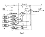
- FIG. 7 shows a system in accordance with the invention, and uses like reference numerals from FIG. 1 and the above noted incorporated patents where appropriate to facilitate clarity.
- a plurality of cancelling acoustic waves are output into the duct from a plurality of output transducers or speakers 14, 214, 314, one for each negative or positive pressure portion of the acoustic wave, for attenuating the output acoustic wave providing the output noise.
- the combined output acoustic wave and the cancelling acoustic waves are sensed by a plurality of error transducers or microphones 16, 216, 316, one for each portion of the acoustic wave, respectively, which error microphones provide error signals at 44, 244, 344, respectively.
- the acoustic system is modeled with a plurality of adaptive filter models 40, 240, 340, one for each portion of the acoustic wave, respectively.
- Each adaptive filter model has an error input 44, 244, 344, from a respective one of the error microphones and outputs a correction signal at 46, 246, 346, to a respective one of the output speakers 14, 214, 314, to introduce the respective auxiliary cancelling acoustic wave.
- the sound from speaker 14 travels back along a feedback path to the input transducer provided by input microphone 10.
- sound from speakers 214 and 314 travel back along feedback paths to input microphone 10.
- the feedback path from speaker 14 to input microphone 10 is modeled with the same model 40 such that model 40 adaptively models both the acoustic system 4 and the feedback path.
- the feedback path from speaker 214 to input microphone 10 is modeled with the same model 240 such that model 240 adaptively models both acoustic system 4 and the noted feedback path.
- the feedback path from speaker 314 to input microphone 10 is modeled with the same model 340 such that model 340 adaptively models both duct 4 and the noted feedback path.
- None of the models 40, 240 or 340 uses separate on-line modeling of duct 4 and off-line modeling of the respective feedback path. Off-line modeling of the respective feedback paths using broadband noise to pre-train a separate dedicated feedback filter is not necessary.
- the feedback path is part of the model used for adaptively modeling the entire system.
- Each model is an adaptive recursive filter model having a transfer function with both poles and zeros, as in the noted incorporated patents. The use of poles to model the feedback path is significant.
- Individual finite impulse response (FIR) filters are not adequate to truly adaptively cancel direct and feedback noise. Instead, a single infinite impulse response (IIR) filter is needed to provide truly adaptive cancellation of the direct noise and acoustic feedback.
- each of models 40, 240 and 340 adaptively recursively models the acoustic system and the feedback path on-line. Since each model is recursive, it provides the IIR characteristic present in the acoustic feedback loop wherein an impulse will continually feed upon itself in feedback manner to provide an infinite response.
- the feedback path from speaker 14 to input microphone 10 is modeled by using the error signal at 44.
- the feedback paths from speakers 214 and 314 to input microphone 10 are modeled by using the respective error signals at 244 and 344 from respective error microphones 216 and 316.
- the feedback path from speaker 14 to input microphone 10 is modeled by using the error signal at 44 as one input to model 40 and the correction signal at 46 as another input to model 40, FIG. 7 of incorporated U.S. Patent 4,677,676.
- each of the feedback paths from speakers 214 and 314 to input microphone 10 are modeled by using the respective error signals at 244 and 344 from the respective error microphones 216 and 316 as one input to the respective models 240 and 340 and the respective correction signals 246 and 346 to the respective speakers 214 and 314 as another input to the respective model 240 and 340 as in FIG. 7 of incorporated U.S. Patent 4,677,676.
- the system of FIG. 7 increases the frequency range of the active acoustic attenuation system above f c .
- N acoustic waves are output into the duct from N output transducer speakers 14, 214, 314, for attenuating the output acoustic wave providing the output noise at 8.
- the combined output acoustic wave and the N acoustic waves from the N speakers are sensed with N error transducers 16, 216, 316, providing N error signals 44, 244, 344.
- N 3.
- One or more input signals representing the input acoustic wave providing the input noise at 6 are provided to the adaptive filter models 40, 240, 340. Only a single input signal need be provided, and the same such input signal may be input to each of the adaptive filter models, at 42.
- an input microphone 10 provides a single input transducer sensing the input acoustic wave and supplying such input signal.
- the input signal may be provided by a transducer such as a tachometer which provides the frequency of a periodic input acoustic wave such as from an engine or the like.
- the input signal may be provided by one or more error signals, in the case of a periodic noise source, J.C. Burgess, Journal of Acoustic Society of America, 70(3), Sep. 1981, pp. 715-726.
- a plurality of input transducers such as microphones 10, 210, 310, may be provided, each sensing the input noise and providing a separate input signal respectively to models 40, 240, 340. It has been found that multiple input microphones are not needed. It is believed that this is because the acoustic pressure at position 10 is related to the acoustic pressure at the other positions such as 210 and 310 by appropriate transfer functions which are adaptively modeled and compensated in the respective models by the coefficients in the numerators and denominators of the IIR pole-zero filter models, particularly if a high number of coefficients are used.
- N random noise sources 140, 241, 341 introduce noise into each of the N models 40, 240, 340, respectively, such that each of the N error microphones 16,216,316, respectively, also senses the auxiliary noise from the auxiliary noise sources and additionally models each respective output transducer speaker 14, 214, 314, and each respective error path from each respective speaker to each respective error microphone 16, 216, 316, respectively, all on-line without separate modeling and without dedicated pretraining, as in FIGs. 19 and 20 of incorporated U.S. Patent 4,677,676.
- the noise from each auxiliary noise source is random and uncorrelated to the input acoustic wave providing the input noise at 6, and is provided by a Galois sequence, M.P.
- the Galois sequence is a psuedorandom sequence that repeats after 2 M - 1 , where M is the number of stages in a shaft register.
- M is the number of stages in a shaft register.
- the Galois sequence is preferred because it it easy to calculate and can easily have a period much longer than the response time of the system.
- the auxiliary noise sources 140, 241, 341, enable additional adaptive modeling of the characteristics of each of the speakers 14, 214, 314, and the error paths from such speakers to the output microphones, 16, 216, 316, on an on-line basis.
- local baffles 4a, 4b are provided in duct 4 between the speakers 14, 214, 314, to minimize interaction between the speakers.
- the baffles are local and extend only adjacent the speakers, and do not extend along the length of the duct nor between the output microphones 16, 216, 316.
- Local baffles are easy to install during installation of the speakers 14, 214, 314, and do not involve substantial additional retrofit cost as compared to splitting or otherwise partitioning the duct into separate ducts or chambers along the entire or substantially the entire axial length thereof.
- Each model 40, 240, 340 comprises a recursive least mean square filter including a first algorithm 12, FIG. 7 of incorporated U.S. Patent 4,677,676, having a first input 42 from the input microphone, a second input 49 from its respective error signal 44 from its respective error microphone, and an output, and a second algorithm 22 having a first input from its respective correction signal 46 to its respective output speaker, a second input 47 from its respective error signal 44 from its respective error microphone, and an output, and a summing junction 48 having inputs from the outputs of the first and second algorithms, and an output providing the respective correction signal 46 to the respective one of the N output speakers.
- each of the N models 40, 240, 340 includes a first algorithm 12 having a first input 42 from the input microphone, a second input 49 from the respective error signal 44 from its respective one of the N error microphones, and an output, a first summing junction 52 having a first input from the respective error signal 44 from the respective one of the N error microphones, a second input from the respective correction signal 46 to the respective one of the N speakers, and an output 54, second algorithm means 22 having a first input from the output 54 of the first summing junction 52, a second input 47 from the respective error signal 44 from the respective one of the N error microphones and an output, and a second summing junction 48 having inputs from the outputs of the first and second algorithms 12 and 22, and an output providing the respective correction signal 46 to the respective one of the N output speakers.
- the system of FIG. 7 may be extended for use in both transverse dimensions of the duct for applications where both transverse dimensions are greater than a half wavelength resulting in higher order modes that have non-uniform sound fields in both transverse directions at a given instant in time.
- the system of FIG. 7 may be extended for use in circular ducts containing higher order modes that have non-uniform sound fields in both radial and circumferential directions at a given instant in time.
- the active attenuation system of FIG. 7 may be used for attenuation of an undesired elastic wave in an elastic medium.
- the elastic wave has non-uniform pressure distribution in the medium at a given instant in time along a direction transverse to the direction of propagation such that the wave has a plurality of portions along the transverse direction at the given instant in time including at least one positive pressure portion and at least one negative pressure portion.
Landscapes
- Physics & Mathematics (AREA)
- Engineering & Computer Science (AREA)
- Acoustics & Sound (AREA)
- Multimedia (AREA)
- Soundproofing, Sound Blocking, And Sound Damping (AREA)
- Pipe Accessories (AREA)
- Duct Arrangements (AREA)
- Circuit For Audible Band Transducer (AREA)
Claims (33)
- Aktive Schalldämpfungsanordnung zur Dämpfung unerwünschter elastischer Wellenausbreitung in einem elastischen Medium einer akustischen Anordnung, wobei die elastische Welle in dem Medium zu einem vorgegebenen Zeitpunkt entlang einer Richtung eine derart quer zur Ausbreitungsrichtung ungleichförmige Druckverteilung aufweist, daß die Welle eine Mehrzahl von Abschnitten entlang der Querrichtung aufweist, mit wenigstens einem positivem Druckabschnitt (406) und einem negativen Druckabschnitt (406), dadurch gekennzeichnet, daß folgende Mittel vorgesehen sind:
eine Mehrzahl von Ausgabewandlern (4, 214, 314) jeweils für die positiven und die negativen Druckabschnitte der unerwünschten elastischen Welle, wobei die Ausgabewandler eine Mehrzahl von auslöschenden elastischen Wellen in das Medium einbringen;
eine Mehrzahl von Abweichungswandlern (16, 216, 316) jeweils für die positiven und die negativen Druckabschnitte der unerwünschten elastischen Welle, wobei die Abweichungswandler die mit den auslöschenden elastischen Wellen vereinigte unerwünschte elastische Welle erfassen und eine Mehrzahl von Abweichungssignalen (44, 244, 344) zur Verfügung stellen; und
eine Mehrzahl von adaptiven Filterformern (40, 240, 340), die die akustische Anordnung in einem jeden der positiven und negativen der Druckabschnitte der unerwünschten elastischen Welle arbeiten läßt, wobei jeder Former über einen Abweichungseingang (44, 244, 344) für einen zugehörigen der Abweichungswandler verfügt und ein Korrektursignal (46, 246, 346) an einen zugehörigen der Ausgabewandler abgibt, um eine zugehörige der auslöschenden elastischen Wellen in der Weise einzuleiten, daß ein jeder Abschnitt der unerwünschten elastischen Welle über seine zugehörige Anordnung aus adaptivem Filterformer, Ausgabewandler und Abweichungswandler verfügt. - Aktive Schalldämpfungsanordnung nach Anspruch 1 für eine akustische Anordnung mit einem axial erweiterten Rohr (4), das eine Eintrittsöffnung (6) für die unerwünschte elastische Welle aufweist, die sich dahindurch zu einer Austrittsöffnung (8) ausbreitet, und worin die unerwünschte elastische Welle N sich transversal quer hindurch erstrechende Abschnitte aufweist, wobei N ≧ 2, und wenigstens den einen positiven und den einen negativen Druckabschnitt enthält, mit:
N der adaptiven Filterformer, die die akustische Anordnung in anpassungsfähiger Weise arbeiten läßt, wobei jeder Former über einen zugehörigen Abweisungseingang (44, 244, 344) für einen zugehörigen der N Abweichungswandler verfügt und das Korrektursignal (46, 246, 346) an einen zugehörigen der N Ausgabewandler (14, 214, 314) abgibt, um eine eigene der N auslöschenden Wellen in der Weise einzuleiten, daß sich ein jedes der N Abweichungssignale einem vorgegebenen Wert annähert. - Aktive Schalldämpfungsanordnung nach Anspruch 2 mit Aufnahmewandlern (10, 210, 310), die ein oder mehrere Aufnahmesignale (42) erzeugen, die die unerwünschte elastische Welle an der Eingangsöffnung repräsentieren, in der jeder der N Filterformer die akustische Anordnung in anpassungsfähiger Weise direktgekoppelt arbeiten läßt, ohne sich systemunabhäniger Voreinstellung zu widmen, wobei auch der Rückkopplungsweg vom zugehörigen der N Ausgabewandler zum Aufnahmewandler direktgekoppelt sowohl für breitbandige als auch für schmalbandige akustische Wellen erfolgt, ohne sich systemunabhängiger Voreinstellung zu widmen, und wobei dessen Korrektursignal dem zugehörigen der N Ausgabewandler zugeführt wird, um die zugehörige der N auslöschenden Wellen einzufügen.
- Aktive Schalldämpfungsanordnung nach Anspruch 3, in der jeder der N Former Mittel enthält, die den eigenen Rückkopplungsweg als Teil des eigenen Formers arbeiten läßt, ohne einen gesonderten Former, der sich allein dem Rückkopplungsweg und dessen Voreinstellung widmet.
- Aktive Schalldämpfungsanordnung nach Anspruch 3 oder 4, deren Former ein adaptives Rekursivfilter enthält.
- Aktive Schalldämpfungsanordnung nach Anspruch 5, in der jedes der Filter eine Übertragungsfunktion sowohl mit Polen als auch mit Nullstellen hat.
- Aktive Schalldämpfungsanordnung nach Anspruch 6, in der jeder Former ein rekusives kleinstgemitteltes Quadratfilter enthält.
- Aktive Schalldämpfungsanordnung nach Anspruch 3 oder 4, in der jeder der N Former ausgerüstet ist mit:
ersten Algorithmiermitteln mit einem ersten Eingang für den Aufnahmewandler, einem zweiten Eingang für das Abweichungssignal aus dem zugehörigen der N Abweichungswandler und einem Ausgang;
zweiten Algorithmiermitteln mit einem ersten Eingang für das Korrektursignal aus einem zugehörigen der N Ausgabewandler, einem zweiten Eingang für das Abweichungssignal aus einem zugehörigen der N Korrekturwandler und mit einem Ausgang;
einer Summierverbindung mit Eingängen für die Ausgänge der ersten und zweiten Algorithmiermittel und mit einem Ausgang, der das zugehörige Korrektursignal an den zugehörigen der N Ausgabewandler liefert. - Aktive Schalldämpfungsanordnung nach Anspruch 3 oder 4, in der ein jeder der N Former folgende Mittel enthält:
erste Algorithmiermittel mit einem ersten Eingang für den Aufnahmewandler, einem zweiten Eingang für das Abweichungssignal aus dem zugehörigen der N Abweichungswandler, und mit einem Ausgang;
zweite Algorithmiermittel mit einem ersten Eingang für die ausgegebene auslöschende Welle, einem zweiten Eingang für das Korrektursignal aus dem zugehörigen der N Korrekturwandler und mit einem Ausgangs; und
eine Summierverbindung mit Eingängen für die Ausgänge der ersten und zweiten Algorithmiermittel und mit einem Ausgang, der das zugehörige Korrektursignal an den zugehörigen der N Ausgabewandler liefert. - Aktive Schalldämpfungsanordnung nach Anspruch 3 oder 4, in der ein jeder der N Former folgende Mittel enthält:
erste Algorithmiermittel mit einem ersten Eingang für den Aufnahmewandler, einem zweiten Eingang für das Abweichungssignal aus dem zugehörigen der N Abweichungswandler und mit einem Ausgang;
eine erste Summierverbindung mit einem ersten Eingang für das zugehörige Abweichungssignal aus dem zugehörigen der N Abweichungswandler, einem zweiten Eingang für das zugehörige Korrektursignal an den zugehörigen der N Ausgabewandler und mit einem Ausgang;
zweite Algorithmiermittel mit einem ersten Eingang für den Ausgang der ersten Summierverbindung, einem zweiten Eingang, für das zugehörige Abweichungssignal aus dem zugehörigen der Abweichungswandler und mit einem Ausgang; und
eine zweite Summierverbindung mit Eingänge für die Ausgänge der ersten und zweiten Algorithmiermittel und mit einem Ausgang, der das zugehörige Korrektursignal an den zugehörigen der Ausgabewandler liefert. - Aktive Schalldämpfungsanordnung nach einem der Ansprüche 3 bis 10, deren N Abweichungswandler jeweils ein Mikrofon ist, deren Aufnahmewandler ein oder mehrere Mikrofone umfaßt und deren N Ausgabewandler jeweils ein Lautsprecher ist.
- Aktive Schalldämpfungsanordnung nach einem der Ansprüche 2 bis 11 mit:
zusätzlichen Rauscherzeugnungsmitteln (140, 241, 341), die zusätzliches Rauschen in jeden der N adaptiven Filterformer einfügen, das statisch verteilt und mit der unerwünschten elastischen Welle an der Eingangsöffnung nicht korelliert ist; und
einem zweiten Satz von N adaptiven Filterformern, von denen jeder einen Eingang für das zusätzliche Rauschen aufweist sowie einen Abweichungseingang für einen der N Abweichungswandler. - Aktive Schalldämpfungsanordnung nach Anspruch 12 mit Summiermitteln, die das zusätzliches Rauschen aus den zusätzlichen Rauscherzeugungsmitteln mit den Ausgangssignalen der ersterwähnten N Filterformer aufsummieren und die das Ergebnis als das zugehörige Korrektursignal an den zugehörigen der N Ausgabewandler abgeben.
- Aktive Schalldämpfungsanordnung nach Anspruch 13, in der jeder, der adaptiven Filterformer des zweiten Satzes von N Formern Algorithmiermittel enthält, wobei die Anordnung weiterhin zweite Summiermittel zur Summierung der Ausgangssignale von dem zugehörigen der Abweichungswandler und von den N Abweichungswandlern enthält, sowie Multipliziermitteln, die die Ausgangssignale der zweiten Summiermittel mit zusätzlichem Rauschen aus den zusätzlichen Rauscherzeugungsmitteln verknüpfen und das Produkt als Aktualisierungssignal den Algorithmiermitteln eingeben.
- Aktive Schalldämpfungsanordnung nach Anspruch 12, in der jeder der N adaptiven Filterformer die akustische Anordnung direkt gekoppelt arbeiten läßt, ohne sich systemunabhängiger Voreinstellung zu widmen, und auch den Rückkopplungsweg vom zugehörigen der N Ausgabewandler zum Aufnahmewandler direkt gekoppelt arbeiten läßt, ohne sich systemunabhängiger Voreinstellung zu widmen, wobei jeder der N Former einen Formereingang für den Aufnahmewandler und einen Abweichungseingang für den zugehörigen der N Abweichungswandler aufweist, um die zugehörige der N auslöschenden Wellen in der Weise einzubringen, daß sich das zugehörige der N Abweichungssignale einem vorgegebenen Wert aufgleicht,
und in der von dem zweiten Satz N adaptiver Filterformer ein jeder adaptiv sowohl einen zugehörigen Abweichweg als auch einen zugehörigen der N Ausgabewandler direktgekoppelt arbeiten läßt, ohne sich systemunabhängiger Voreinstellung zu widmen; und
zu der eine Kopie eines jeden Formers im zweiten Satz der N adaptiven Filterformer vorgesehen ist, von denen sich jede Kopie in einem zugehörigen der zuersterwähnten N adaptiven Filterformer befindet um sowohl den zugehörigen Abweichungsweg als auch das zugehörigen der N Ausgabewandler direkt gekoppelt zu kompensieren. - Aktive Schalldämpfungsanordnung nach einem der Ansprüche 2 bis 15, mit örtlichem Schallwand-Mitteln in dem Rohr zwischen den N Ausgabewandlern zur Minimierung von Wechselwirkungen untereinander, wobei die Schallwand-Mittel lokal bei den Ausgabewandlern angeordnet sind und sich nicht zwischen den N Abweichungswandlern erstrecken.
- Verfahren zur Dämpfung unerwünschter elastischer Wellenausbreitung in einem elastischen Medium, wobei die elastische Welle in dem Medium quer zur Ausbreitungsrichtung eine derart ungleichförmige Druckverteilung aufweist, daß die Welle eine Mehrzahl von Abschnitten entlang der Querrichtung aufweist mit wenigstens einem positiven Druckabschnitt (404) und mit wenigstens einem negativen Druckabschnitt (406), gekennzeichnet durch folgende Verfahrensschritte:
Einfügung einer Mehrzahl von auslöschenden elastischen Wellen aus einer Mehrzahl von Augabewandlern (14, 214, 314) jeweils für die positiven und negativen Druckabschnitte der unerwünschten elastischen Welle, um die unerwünschte elastische Welle zu dämpfen;
Erfassung der mit den auslöschenden elastischen Wellen vereinigten unerwünschten Welle mit einer Mehrzahl von Abweichungswandlern (16, 216, 316) jeweils für die positiven und die negativen Druckabschnitte der unerwünschten elastischen Welle sowie zur Verfügungstellung einer Mehrzahl von Abweichungssignalen (44, 244, 344); und
Formung der akustischen Anordnung mit einer Mehrzahl adaptiver Filterformer (40, 240, 340) von denen jeweils einer für die positiven und auch die negativen Druckabschnitte der unerwünschten elastischen Welle ist, wobei jeder Former einen Abweichungseingang (44, 244, 344) für einen zugehörigen der Abweichungswandler aufweist und ein Korrektursignal ( 46, 246, 346) an einen zugehörigen der Ausgabewandler abgibt, um die auslöschende elastische Welle in der Weise einzuleiten, daß jeder Abschnitt der unerwünschten elastischen Welle über seine zugehörige Anordnung aus adaptivem Filterformer, Ausgabewandler und Abweichungswandler verfügt. - Verfahren nach Anspruch 17, für eine akustische Anordnung mit einem axial erweiterten Rohr (4), das eine Eintrittsöffnung (6) für die unerwünschte elastische Welle aufweist, die sich dahindurch zu einer Austrittsöffnung (8) ausbreitet, und worin die unerwünschte elastische Welle N sich transversal quer hindurch erstrechende Abschnitte aufweist, wobei N ≦ 2, und wenigsten den einen positiven und den einen negativen Durckabschnitt enthält, das folgende Verfahrensschritte umfaßt:
Formung der akustischen Anordnung mit der adaptiven Filterformer, die jeweils über einen zugehörigen Abweichungseingang (44, 244, 344) für einen zugehörigen der N Abweichungswandler verfügen und das Korrektursignal (46, 246, 346) an einen zugehörigen der N Ausgabewandler (14, 214, 314) abgibt, um eine zugehörige der N auslöschenden Wellen in der Weise einzuleiten, daß sich jedes der N Abweichungssignale einem vorgegebenen Wert annähert. - Verfahren nach Anspruch 17 oder 18, nach dem die akustische Anordnung mit adaptiven Rekursivfilterformern geformt wird, von denen jeder eine Übertragungsfunktion sowohl mit Polen als auch mit Nullstellen aufweist.
- Verfahren nach Anspruch 17 oder 19, nach dem die Formung der akustischen Anordnung mit adaptiven rekursiven kleinstgemittelten Quadratfilterformern erfolgt.
- Verfahren nach einem der Ansprüche 12 bis 20, mit folgenden Verfahrensschritten:
Feststellen unerwünschten elastischen Welle am Eingang mit Aufnahmewandlern (10, 210, 310);
Formung eines jeden der N Rückkoppelwege von den Ausgabewandlern zu den Aufnahmewandlern mit dem gleichen zugehörigen adaptiven Filterformer ohne gesonderte Formungs-Voreinstellung lediglich des zugehörigen Rückkopplungsweges, indem jeder der Rückkopplungswege als Teil des zugehörigen adaptiven Filterformers in der Weise geformt wird, daß jeder adaptive Filterformer sowohl die akustische Anordnung als auch den zugehörigen Rückkopplungsweg formt, ohne getrennte Formung der akustischen Anordnung und des zugehörigen Rückkopplungsweges und ohne sich Voreinstellungen der zugehörigen adaptiven Filterformer mit einem breitbandigen akustischen Signal zu widmen. - Verfahren nach Anspruch 21, das die Formung eines jeden der Rückkopplungswege beinhaltet, wobei das zugehörige Abweichungssignal aus dem zugehörigen Abweichungswandler benutzt wird.
- Verfahren nach Anspruch 21, das die Formung eines jeden der Rückkopplungswege beinhaltet, wobei das zugehörige Abweichungssignal aus dem zugehörigen Abweichungswandler benutzt wird als ein Eingangssignal für den zugehörigen Former und das zugehörige Korrektursignal für den zugehörigen Ausgabewandler als ein weiteres Eingangssignal für den zugehörigen Former.
- Verfahren nach Anspruch 18, nach dem ein oder mehrere Eingangssignale zur Verfügung gestellt werden, die die unerwünschte elastische Welle an der Eingangsöffnung repräsentieren, und nach dem die Formung der akustischen Anordnung mit den adaptiven Filterformern erfolgt, deren Eingänge das eine oder die mehreren Eingangssignale empfangen.
- Verfahren nach Anspruch 24, nach dem ein einziges Eingangssignal zur Verfügung gestellt wird, das die unerwünschte elastische Welle repäsentiert und das jedem der Filterformer zugeführt wird.
- Verfahren nach Anspruch 25, nach dem ein einziger Aufnahmewandler die unerwünschte elastische Welle an der Eingangsöffnung aufnimmt und das Eingangssignal liefert.
- Verfahren nach Anspruch 24, nach dem die Eingangssignale in einer Mehrzahl zur Verfügung gestellt werden, von denen jeweils eines für einen Filterformer vorgesehen ist.
- Verfahren nach Anspruch 27, nach dem eine Vielzahl von Aufnahmewandlern zur Verfügung steht, die die unerwünschte elastische Welle aufnehmen und die zugehörigen Eingangssignale liefern.
- Verfahren nach einem der Ansprüche 17 bis 29, nach dem zusätzliche Rauscherzeugungsmittel (140, 241, 341) zur Verfügung stehen, die zusätzliches Rauschen in jeden Former in der Weise einfügen, daß jeder der Abweichungswandler auch das zusätzliche Rauschen aus den zusätzlichem Rauscherzeugungsmitteln aufnimmt.
- Verfahren nach Anspruch 29, nach dem die Former zusätzlich jeden zugehörigen Ausgabewandler und jeden zugehörigen Abweichungsweg von jedem zugehörigen Ausgabewandler zu jedem zugehörigen Abweichungswandler direkt gekoppelt formen, ohne gesonderte Formung und ohne sich Voreinstellungen zu widmen.
- Verfahren nach Anspruch 29 oder 30, nach dem eingefügtes Rauschen aus den zusätzlichen Rauscherzeugungsmitteln statisch verteilt und mit der unerwünschten elastischen Welle an der Eingangsöffnung nicht korreliert ist.
- Verfahren nach Anspruch 31, nach dem die zusätzlichen Rauscherzeugungsmittel N zusätzliche Rauschquellen sind, und die Einfügung des Rauschens aus jeder der N Rauschquellen in einen zugehörigen der Former in der Weise beinhaltet, daß jeder Abweichungswandler auch das zusätzliche Rauschen aus seiner zugehörigen Rauschquelle unter den N zusätzlichen Rauschquellen aufnimmt.
- Verfahren nach einem der Ansprüche 17 bis 32, nach dem in dem Rohr zwischen den Ausgabewandlern örtliche Schallwand-Mittel vorgesehen sind, um gegenseitige Wechselwirkungen zu minimieren.
Priority Applications (1)
| Application Number | Priority Date | Filing Date | Title |
|---|---|---|---|
| AT89302561T ATE91035T1 (de) | 1988-03-16 | 1989-03-15 | Aktive schalldaempfungsanordnung fuer ein nichtuniformes schallfeld hoeherer ordnung in einem rohr. |
Applications Claiming Priority (2)
| Application Number | Priority Date | Filing Date | Title |
|---|---|---|---|
| US168932 | 1988-03-16 | ||
| US07/168,932 US4815139A (en) | 1988-03-16 | 1988-03-16 | Active acoustic attenuation system for higher order mode non-uniform sound field in a duct |
Publications (3)
| Publication Number | Publication Date |
|---|---|
| EP0333461A2 EP0333461A2 (de) | 1989-09-20 |
| EP0333461A3 EP0333461A3 (en) | 1990-03-14 |
| EP0333461B1 true EP0333461B1 (de) | 1993-06-23 |
Family
ID=22613557
Family Applications (1)
| Application Number | Title | Priority Date | Filing Date |
|---|---|---|---|
| EP89302561A Expired - Lifetime EP0333461B1 (de) | 1988-03-16 | 1989-03-15 | Aktive Schalldämpfungsanordnung für ein nichtuniformes Schallfeld höherer Ordnung in einem Rohr |
Country Status (7)
| Country | Link |
|---|---|
| US (1) | US4815139A (de) |
| EP (1) | EP0333461B1 (de) |
| JP (1) | JPH01274598A (de) |
| AT (1) | ATE91035T1 (de) |
| AU (1) | AU608423B2 (de) |
| CA (1) | CA1296649C (de) |
| DE (1) | DE68907241T2 (de) |
Families Citing this family (70)
| Publication number | Priority date | Publication date | Assignee | Title |
|---|---|---|---|---|
| US4837834A (en) * | 1988-05-04 | 1989-06-06 | Nelson Industries, Inc. | Active acoustic attenuation system with differential filtering |
| DE68921890T2 (de) * | 1988-07-08 | 1995-07-20 | Adaptive Audio Ltd | Tonwiedergabesysteme. |
| US4899387A (en) * | 1988-12-02 | 1990-02-06 | Threshold Corporation | Active low frequency acoustic resonance suppressor |
| US5091954A (en) * | 1989-03-01 | 1992-02-25 | Sony Corporation | Noise reducing receiver device |
| US5033082A (en) | 1989-07-31 | 1991-07-16 | Nelson Industries, Inc. | Communication system with active noise cancellation |
| US4969129A (en) * | 1989-09-20 | 1990-11-06 | Texaco Inc. | Coding seismic sources |
| US5022082A (en) * | 1990-01-12 | 1991-06-04 | Nelson Industries, Inc. | Active acoustic attenuation system with reduced convergence time |
| US5044464A (en) * | 1990-01-23 | 1991-09-03 | Nelson Industries, Inc. | Active acoustic attenuation mixing chamber |
| JP2573389B2 (ja) * | 1990-03-23 | 1997-01-22 | 晴夫 浜田 | 電子消音方法及び装置 |
| US5233137A (en) * | 1990-04-25 | 1993-08-03 | Ford Motor Company | Protective anc loudspeaker membrane |
| US5119902A (en) * | 1990-04-25 | 1992-06-09 | Ford Motor Company | Active muffler transducer arrangement |
| US5323466A (en) * | 1990-04-25 | 1994-06-21 | Ford Motor Company | Tandem transducer magnet structure |
| US5229556A (en) * | 1990-04-25 | 1993-07-20 | Ford Motor Company | Internal ported band pass enclosure for sound cancellation |
| US5319165A (en) * | 1990-04-25 | 1994-06-07 | Ford Motor Company | Dual bandpass secondary source |
| US5063598A (en) * | 1990-04-25 | 1991-11-05 | Ford Motor Company | Active noise control system with two stage conditioning |
| US4987598A (en) * | 1990-05-03 | 1991-01-22 | Nelson Industries | Active acoustic attenuation system with overall modeling |
| US5060271A (en) * | 1990-05-04 | 1991-10-22 | Ford Motor Company | Active muffler with dynamic tuning |
| US5088575A (en) * | 1990-09-13 | 1992-02-18 | Nelson Industries, Inc. | Acoustic system with transducer and venturi |
| US5396561A (en) * | 1990-11-14 | 1995-03-07 | Nelson Industries, Inc. | Active acoustic attenuation and spectral shaping system |
| US5172416A (en) * | 1990-11-14 | 1992-12-15 | Nelson Industries, Inc. | Active attenuation system with specified output acoustic wave |
| US5255321A (en) * | 1990-12-05 | 1993-10-19 | Harman International Industries, Inc. | Acoustic transducer for automotive noise cancellation |
| US5511127A (en) * | 1991-04-05 | 1996-04-23 | Applied Acoustic Research | Active noise control |
| US5216721A (en) * | 1991-04-25 | 1993-06-01 | Nelson Industries, Inc. | Multi-channel active acoustic attenuation system |
| US5224168A (en) * | 1991-05-08 | 1993-06-29 | Sri International | Method and apparatus for the active reduction of compression waves |
| US5283834A (en) * | 1991-08-26 | 1994-02-01 | Nelson Industries, Inc. | Acoustic system suppressing detection of higher order modes |
| US5347585A (en) * | 1991-09-10 | 1994-09-13 | Calsonic Corporation | Sound attenuating system |
| US5216722A (en) * | 1991-11-15 | 1993-06-01 | Nelson Industries, Inc. | Multi-channel active attenuation system with error signal inputs |
| US5210805A (en) * | 1992-04-06 | 1993-05-11 | Ford Motor Company | Transducer flux optimization |
| JPH0596900U (ja) * | 1992-05-30 | 1993-12-27 | 高砂熱学工業株式会社 | ビル用空調設備の電子消音装置 |
| US5278913A (en) * | 1992-07-28 | 1994-01-11 | Nelson Industries, Inc. | Active acoustic attenuation system with power limiting |
| US5390255A (en) * | 1992-09-29 | 1995-02-14 | Nelson Industries, Inc. | Active acoustic attenuation system with error and model copy input |
| US5692053A (en) * | 1992-10-08 | 1997-11-25 | Noise Cancellation Technologies, Inc. | Active acoustic transmission loss box |
| EP0664044B1 (de) * | 1992-10-08 | 1999-09-15 | NCT Group, Inc. | Gehäuse mit aktiv erzeugtem akustischem Übertragungsverlust |
| GB2271909B (en) * | 1992-10-21 | 1996-05-22 | Lotus Car | Adaptive control system |
| US5386477A (en) * | 1993-02-11 | 1995-01-31 | Digisonix, Inc. | Active acoustic control system matching model reference |
| US5526421A (en) * | 1993-02-16 | 1996-06-11 | Berger; Douglas L. | Voice transmission systems with voice cancellation |
| US5416845A (en) * | 1993-04-27 | 1995-05-16 | Noise Cancellation Technologies, Inc. | Single and multiple channel block adaptive methods and apparatus for active sound and vibration control |
| US5812682A (en) * | 1993-06-11 | 1998-09-22 | Noise Cancellation Technologies, Inc. | Active vibration control system with multiple inputs |
| US5519637A (en) * | 1993-08-20 | 1996-05-21 | Mcdonnell Douglas Corporation | Wavenumber-adaptive control of sound radiation from structures using a `virtual` microphone array method |
| US5420932A (en) * | 1993-08-23 | 1995-05-30 | Digisonix, Inc. | Active acoustic attenuation system that decouples wave modes propagating in a waveguide |
| EP0585976A3 (en) * | 1993-11-10 | 1994-06-01 | Phonak Ag | Hearing aid with cancellation of acoustic feedback |
| NL9302013A (nl) * | 1993-11-19 | 1995-06-16 | Tno | Systeem voor snelle convergentie van een adaptief filter bij het genereren van een tijdvariant signaal ter opheffing van een primair signaal. |
| US5586189A (en) * | 1993-12-14 | 1996-12-17 | Digisonix, Inc. | Active adaptive control system with spectral leak |
| US5660255A (en) * | 1994-04-04 | 1997-08-26 | Applied Power, Inc. | Stiff actuator active vibration isolation system |
| CA2148962C (en) * | 1994-05-23 | 2000-03-28 | Douglas G. Pedersen | Coherence optimized active adaptive control system |
| US5557682A (en) * | 1994-07-12 | 1996-09-17 | Digisonix | Multi-filter-set active adaptive control system |
| US5606622A (en) * | 1994-09-29 | 1997-02-25 | The Boeing Company | Active noise control in a duct with highly turbulent airflow |
| WO1996012269A1 (en) * | 1994-10-13 | 1996-04-25 | The Boeing Company | Jet engine fan noise reduction system utilizing electro pneumatic transducers |
| US5570425A (en) * | 1994-11-07 | 1996-10-29 | Digisonix, Inc. | Transducer daisy chain |
| US5498127A (en) * | 1994-11-14 | 1996-03-12 | General Electric Company | Active acoustic liner |
| US5561598A (en) * | 1994-11-16 | 1996-10-01 | Digisonix, Inc. | Adaptive control system with selectively constrained ouput and adaptation |
| US5478199A (en) * | 1994-11-28 | 1995-12-26 | General Electric Company | Active low noise fan assembly |
| US5526292A (en) * | 1994-11-30 | 1996-06-11 | Lord Corporation | Broadband noise and vibration reduction |
| US5754662A (en) * | 1994-11-30 | 1998-05-19 | Lord Corporation | Frequency-focused actuators for active vibrational energy control systems |
| KR19990028737A (ko) * | 1995-07-05 | 1999-04-15 | 알. 피. 울프 | 도관내고차원모드의활성소음제어방법및장치ㅡㅁ제어방법및장치 |
| US5699437A (en) * | 1995-08-29 | 1997-12-16 | United Technologies Corporation | Active noise control system using phased-array sensors |
| JP3654980B2 (ja) * | 1995-11-30 | 2005-06-02 | 富士通株式会社 | 能動騒音制御装置及び波形変換装置 |
| US5702230A (en) * | 1996-01-29 | 1997-12-30 | General Electric Company | Actively controlled acoustic treatment panel |
| US5832095A (en) * | 1996-10-18 | 1998-11-03 | Carrier Corporation | Noise canceling system |
| US5919029A (en) * | 1996-11-15 | 1999-07-06 | Northrop Grumman Corporation | Noise absorption system having active acoustic liner |
| EP0999540A1 (de) * | 1998-11-03 | 2000-05-10 | Nederlandse Organisatie Voor Toegepast-Natuurwetenschappelijk Onderzoek Tno | Anordnung von Lärmdämpfungsplatten und Verfahren zum Kalibrieren einer solchen Plattenanordnung |
| GB9920883D0 (en) * | 1999-09-03 | 1999-11-10 | Titon Hardware | Ventilation assemblies |
| ATE248497T1 (de) * | 1999-12-09 | 2003-09-15 | Frederick Johannes Bruwer | Sprachsverteilungssystem |
| US7448382B1 (en) | 2002-11-12 | 2008-11-11 | Ric Investments, Llc | Pressure support system with active noise cancellation |
| JP4742226B2 (ja) * | 2005-09-28 | 2011-08-10 | 国立大学法人九州大学 | 能動消音制御装置及び方法 |
| US8302456B2 (en) * | 2006-02-23 | 2012-11-06 | Asylum Research Corporation | Active damping of high speed scanning probe microscope components |
| US20080187147A1 (en) * | 2007-02-05 | 2008-08-07 | Berner Miranda S | Noise reduction systems and methods |
| US9383388B2 (en) | 2014-04-21 | 2016-07-05 | Oxford Instruments Asylum Research, Inc | Automated atomic force microscope and the operation thereof |
| CN107407170B (zh) | 2014-12-19 | 2020-07-17 | 通用电气公司 | 主动噪音控制系统 |
| CN109478402B (zh) | 2016-04-20 | 2023-07-21 | 通用电气公司 | 主动式噪声消除系统和装置 |
Family Cites Families (6)
| Publication number | Priority date | Publication date | Assignee | Title |
|---|---|---|---|---|
| US4473906A (en) * | 1980-12-05 | 1984-09-25 | Lord Corporation | Active acoustic attenuator |
| US4683590A (en) * | 1985-03-18 | 1987-07-28 | Nippon Telegraph And Telphone Corporation | Inverse control system |
| US4677677A (en) * | 1985-09-19 | 1987-06-30 | Nelson Industries Inc. | Active sound attenuation system with on-line adaptive feedback cancellation |
| US4665549A (en) * | 1985-12-18 | 1987-05-12 | Nelson Industries Inc. | Hybrid active silencer |
| US4677676A (en) * | 1986-02-11 | 1987-06-30 | Nelson Industries, Inc. | Active attenuation system with on-line modeling of speaker, error path and feedback pack |
| US4736431A (en) * | 1986-10-23 | 1988-04-05 | Nelson Industries, Inc. | Active attenuation system with increased dynamic range |
-
1988
- 1988-03-16 US US07/168,932 patent/US4815139A/en not_active Expired - Lifetime
-
1989
- 1989-03-15 DE DE89302561T patent/DE68907241T2/de not_active Expired - Lifetime
- 1989-03-15 AU AU31331/89A patent/AU608423B2/en not_active Ceased
- 1989-03-15 AT AT89302561T patent/ATE91035T1/de not_active IP Right Cessation
- 1989-03-15 EP EP89302561A patent/EP0333461B1/de not_active Expired - Lifetime
- 1989-03-15 CA CA000593764A patent/CA1296649C/en not_active Expired - Lifetime
- 1989-03-16 JP JP1064892A patent/JPH01274598A/ja active Pending
Also Published As
| Publication number | Publication date |
|---|---|
| EP0333461A3 (en) | 1990-03-14 |
| AU608423B2 (en) | 1991-03-28 |
| US4815139A (en) | 1989-03-21 |
| DE68907241T2 (de) | 1993-11-11 |
| JPH01274598A (ja) | 1989-11-02 |
| AU3133189A (en) | 1989-09-21 |
| CA1296649C (en) | 1992-03-03 |
| ATE91035T1 (de) | 1993-07-15 |
| EP0333461A2 (de) | 1989-09-20 |
| DE68907241D1 (de) | 1993-07-29 |
Similar Documents
| Publication | Publication Date | Title |
|---|---|---|
| EP0333461B1 (de) | Aktive Schalldämpfungsanordnung für ein nichtuniformes Schallfeld höherer Ordnung in einem Rohr | |
| EP0227372B1 (de) | Hybrider aktiver Schalldämpfer | |
| EP0542457B1 (de) | Vielkanal-aktive Dampfungsanordnung mit Eingabe von Fehlersignalen | |
| EP0455479B1 (de) | Aktives akustisches Dämpfungssystem mit Gesamtmodellierung | |
| US5216721A (en) | Multi-channel active acoustic attenuation system | |
| KR0164237B1 (ko) | 다수의 적응형 필터를 갖는 능동 잡음 소거기 | |
| US5337365A (en) | Apparatus for actively reducing noise for interior of enclosed space | |
| US5206911A (en) | Correlated active attenuation system with error and correction signal input | |
| US4837834A (en) | Active acoustic attenuation system with differential filtering | |
| US4473906A (en) | Active acoustic attenuator | |
| EP0724761B1 (de) | Gerät für rauschkompensation für ein kraftfahrzeug | |
| EP2242044B1 (de) | System zur aktiven Rauschregelung mit einem IRR-Filter | |
| US4669122A (en) | Damping for directional sound cancellation | |
| WO1993025999A1 (en) | A transducer arrangement for active sound cancellation systems | |
| US5748750A (en) | Method and apparatus for active noise control of high order modes in ducts | |
| US5420932A (en) | Active acoustic attenuation system that decouples wave modes propagating in a waveguide | |
| EP0654901A1 (de) | Schnelles Konvergenzsystem eines adaptiven Filters zur Erzeugung eines zeitabhängigen Signals zur Kompensation eines primären Signals | |
| US5283834A (en) | Acoustic system suppressing detection of higher order modes | |
| EP0817165B1 (de) | Lärmkontrollegerät | |
| US5390255A (en) | Active acoustic attenuation system with error and model copy input | |
| Rubenstein et al. | Active cancellation of higher order modes in a duct using recursively-coupled multi-channel adaptive control system | |
| Guicking et al. | Multichannel broadband active noise control in small enclosures | |
| Goodman et al. | Performance of active noise control in large air ducts | |
| JP3395245B2 (ja) | ダクト消音用2次音発生装置 | |
| Elliott | Adaptive control of sound in a duct using an array of secondary loudspeakers |
Legal Events
| Date | Code | Title | Description |
|---|---|---|---|
| PUAI | Public reference made under article 153(3) epc to a published international application that has entered the european phase |
Free format text: ORIGINAL CODE: 0009012 |
|
| AK | Designated contracting states |
Kind code of ref document: A2 Designated state(s): AT BE CH DE ES FR GB GR IT LI LU NL SE |
|
| PUAL | Search report despatched |
Free format text: ORIGINAL CODE: 0009013 |
|
| AK | Designated contracting states |
Kind code of ref document: A3 Designated state(s): AT BE CH DE ES FR GB GR IT LI LU NL SE |
|
| 17P | Request for examination filed |
Effective date: 19900426 |
|
| 17Q | First examination report despatched |
Effective date: 19911028 |
|
| GRAA | (expected) grant |
Free format text: ORIGINAL CODE: 0009210 |
|
| AK | Designated contracting states |
Kind code of ref document: B1 Designated state(s): AT BE CH DE ES FR GB GR IT LI LU NL SE |
|
| PG25 | Lapsed in a contracting state [announced via postgrant information from national office to epo] |
Ref country code: SE Effective date: 19930623 Ref country code: GR Free format text: LAPSE BECAUSE OF FAILURE TO SUBMIT A TRANSLATION OF THE DESCRIPTION OR TO PAY THE FEE WITHIN THE PRESCRIBED TIME-LIMIT Effective date: 19930623 Ref country code: CH Effective date: 19930623 Ref country code: ES Free format text: THE PATENT HAS BEEN ANNULLED BY A DECISION OF A NATIONAL AUTHORITY Effective date: 19930623 Ref country code: BE Effective date: 19930623 Ref country code: LI Effective date: 19930623 Ref country code: AT Effective date: 19930623 Ref country code: NL Effective date: 19930623 |
|
| REF | Corresponds to: |
Ref document number: 91035 Country of ref document: AT Date of ref document: 19930715 Kind code of ref document: T |
|
| REF | Corresponds to: |
Ref document number: 68907241 Country of ref document: DE Date of ref document: 19930729 |
|
| ET | Fr: translation filed | ||
| ITF | It: translation for a ep patent filed | ||
| REG | Reference to a national code |
Ref country code: CH Ref legal event code: PL |
|
| NLV1 | Nl: lapsed or annulled due to failure to fulfill the requirements of art. 29p and 29m of the patents act | ||
| PG25 | Lapsed in a contracting state [announced via postgrant information from national office to epo] |
Ref country code: LU Free format text: LAPSE BECAUSE OF NON-PAYMENT OF DUE FEES Effective date: 19940331 |
|
| PLBE | No opposition filed within time limit |
Free format text: ORIGINAL CODE: 0009261 |
|
| STAA | Information on the status of an ep patent application or granted ep patent |
Free format text: STATUS: NO OPPOSITION FILED WITHIN TIME LIMIT |
|
| 26N | No opposition filed | ||
| REG | Reference to a national code |
Ref country code: GB Ref legal event code: IF02 |
|
| PGFP | Annual fee paid to national office [announced via postgrant information from national office to epo] |
Ref country code: GB Payment date: 20030307 Year of fee payment: 15 |
|
| PG25 | Lapsed in a contracting state [announced via postgrant information from national office to epo] |
Ref country code: GB Free format text: LAPSE BECAUSE OF NON-PAYMENT OF DUE FEES Effective date: 20040315 |
|
| PGFP | Annual fee paid to national office [announced via postgrant information from national office to epo] |
Ref country code: FR Payment date: 20040323 Year of fee payment: 16 |
|
| GBPC | Gb: european patent ceased through non-payment of renewal fee |
Effective date: 20040315 |
|
| PG25 | Lapsed in a contracting state [announced via postgrant information from national office to epo] |
Ref country code: IT Free format text: LAPSE BECAUSE OF NON-PAYMENT OF DUE FEES;WARNING: LAPSES OF ITALIAN PATENTS WITH EFFECTIVE DATE BEFORE 2007 MAY HAVE OCCURRED AT ANY TIME BEFORE 2007. THE CORRECT EFFECTIVE DATE MAY BE DIFFERENT FROM THE ONE RECORDED. Effective date: 20050315 |
|
| PG25 | Lapsed in a contracting state [announced via postgrant information from national office to epo] |
Ref country code: FR Free format text: LAPSE BECAUSE OF NON-PAYMENT OF DUE FEES Effective date: 20051130 |
|
| REG | Reference to a national code |
Ref country code: FR Ref legal event code: ST Effective date: 20051130 |
|
| PGFP | Annual fee paid to national office [announced via postgrant information from national office to epo] |
Ref country code: DE Payment date: 20080415 Year of fee payment: 20 |