EP0543126A1 - Kommunikationskontrolleinrichtung - Google Patents
Kommunikationskontrolleinrichtung Download PDFInfo
- Publication number
- EP0543126A1 EP0543126A1 EP92116917A EP92116917A EP0543126A1 EP 0543126 A1 EP0543126 A1 EP 0543126A1 EP 92116917 A EP92116917 A EP 92116917A EP 92116917 A EP92116917 A EP 92116917A EP 0543126 A1 EP0543126 A1 EP 0543126A1
- Authority
- EP
- European Patent Office
- Prior art keywords
- signal
- reception
- transmission
- destination address
- source
- Prior art date
- Legal status (The legal status is an assumption and is not a legal conclusion. Google has not performed a legal analysis and makes no representation as to the accuracy of the status listed.)
- Granted
Links
Images




Classifications
-
- H—ELECTRICITY
- H04—ELECTRIC COMMUNICATION TECHNIQUE
- H04L—TRANSMISSION OF DIGITAL INFORMATION, e.g. TELEGRAPHIC COMMUNICATION
- H04L12/00—Data switching networks
- H04L12/28—Data switching networks characterised by path configuration, e.g. LAN [Local Area Networks] or WAN [Wide Area Networks]
Definitions
- the present invention relates to a communication control apparatus used in a local area network (LAN) system which is a network on a small scale, especially used in a LAN system or the like installed in a moving body such as a vehicle, for example.
- LAN local area network
- Fig. 1 is a schematic diagram showing a configuration example of a LAN system to be installed in a vehicle as an example of a conventional LAN system
- Fig. 2 is a block diagram showing an outline of inner configuration of a LAN IC as communication control apparatus to whose LAN wiring, a plurality of terminals are connected.
- terminals 41, 42, 43 and 44 are connected to the LAN wiring 1.
- Each of the terminals 41, 42, 43 and 44 is configured by a LAN IC and a microprocessor unit, and explanation on the terminal 42 and 43 will be given here.
- the LAN ICs 2a and 3a of the terminals 42 and 43 are connected.
- Each of the LAN ICs 2a and 3a is connected to each of the microprocessor units (MPU) 2b and 3b which produces and process communication data.
- MPU microprocessor units
- Each of the LAN ICs 2a and 3a is configured as shown in Fig. 2 when the LAN IC 2a is taken for an example.
- reference symbol 5 designates a transmission source address storing unit which stores transmission source address numbers specifying transmission source of data (the terminal 42 in this case), the unit being connected to a transmission signal generating unit 6.
- the transmission signal generating unit 6 converts communication data, obtained by adding transmission source address stored in the transmission source address storing unit 5 to data sent from the microprocessor unit 2b, and further by converting data necessary for communication to be described later, into serial electric signal according to a predetermined communication method to sent it to a transceiver 9.
- reference symbol 7 designates a reception source address storing unit which stores reception source address (having the same meaning of transmission source address, and in this case the terminal 42) for judging whether the data received is destined for itself or not, the unit being connected to a reception signal decoding unit 8.
- the reception signal decoding unit 8 judged whether the signal received is destined for itself or not by the fact that the transmission destination address included in the signal received coincides with the reception source address stored in the reception source address storing unit 7 or not, and judges whether data is normal or not, then converts it into a signal which the microprocessor unit 2b can receive and send it thereto.
- the transceiver 9 converts an electric signal sent from the transmission signal generating unit 6 into the one as intense as the LAN wiring 1 is sufficiently capable of transmission and send it thereto, and the converts the signal received from the LAN wiring 1 into the one which the reception signal decoding unit 8 can easily receive to wave-form-shape it.
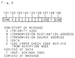
- Fig. 3 is a schematic diagram showing an example of a basic frame format for LAN communication used in units as aforementioned.
- the frames are arranged in order of SOM (Start of Message) 101, A (priority code, that is, priority designation code at detecting of collision) 102, B (transmission destination address) 103, C (transmission source address) 104, D (data) 105, E (CRC error check code) 106, EOD (End Of Data) 107, F (RSP, that is, ACK/NAK code replied by a reception side) 108, and EOM (End Of Message) 109, from the head.
- A priority code, that is, priority designation code at detecting of collision
- B transmission destination address
- C transmission source address
- D data
- E C error check code
- EOD End Of Data
- F RSP, that is, ACK/NAK code replied by a reception side
- EOM End Of Message
- the transmission destination address should be programmed to be reception source address of the terminal 42 stored in advance so that an actuator 20 of the terminal 42 is operated when a switch 30 of the terminal 43 is ON.
- the actuator 20 is operated to move a wiper when a driver turns ON the switch 30, in the case where the LAN system shown in Fig. 1, for example, is installed in a vehicle and the actuator 20 is the one which operates the wiper, and in the case where the switch 30 is a wiper switch.
- the microprocessor 3b detects that the switch 30 is ON and sends as data a signal which represents the fact to the LAN IC 3a.
- the LAN IC 3a transmits to the LAN wiring 1 as an electric signal the signal given from the microprocessor 3b and transmission source address stored in the transmission source address storing unit 5 according to such a basic frame format as shown in Fig. 3 necessary for communication through the transceiver 9.
- each LAN IC 2a or the like In each of the other terminals 41, 42 and 44 connected to the LAn wiring 1, each LAN IC 2a or the like, always receives a signal which is sent, and compares the reception source address of itself stored in each of the reception source address storing unit 7 with the transmission destination address transmitted, and revives the set of the signals when they coincide with each other. And CRC checking is performed to detect whether the data is changed or not, and the reception signal decoding unit 8 executes processings necessary for receiving, and the data is sent to the microprocessor unit 2b (here, the data is assumed to be received by the LAN IC 2a). The microprocessor unit 20 receives this data to drive the actuator 20.
- the conventional communication control apparatus is so configured as aforementioned, even in the case where, for example, a simple signal such as ON/OFF signal of a switch or the like is transmitted, it is necessary to combine a switch with a microcomputer unit and the LAN IC, thereby to bring about a complicated and large sized communication system connected to the apparatus and to the production cost.
- the present invention has been devised in consideration of such circumstances and the object thereof is to provide a communication control apparatus capable of transmitting a signal to each of a plurality of destinations through communication line by one communication apparatus without any assistance of another apparatus and capable of receiving a signal similarly.
- the first invention of the communication control apparatus of the invention is a communication control apparatus which transmits a predetermined signal to a predetermined destination in the case where a signal is inputted from any of a plurality of signal input terminals, and is provided with a transmission source/destination address storing unit which stores transmission source address specifying each of a plurality of signal input terminals and transmission destination address specifying each of destinations made, in advance, correspondence with each of the signal input terminals to each of which signal has been inputted, and a transmission signal generating unit which adds to a predetermined signal a transmission source address and a transmission destination address stored in the transmission source/destination address storing unit corresponding to the signal input terminals to each of which a signal had been inputted, in the case where a signal is inputted from any of a plurality of signal input terminals.
- the second invention is a communication control apparatus which output a signal to any of a plurality of signal output terminals in the case where a predetermined signal is received from a predetermined destined reception destination, and is provided with a reception source/destination address storing unit which stores reception source address specifying respective plurality of signal output terminals and reception destination address specifying transmission source of signals, and a reception signal decoding unit which compares transmission destination/source address included in signal received with a reception source/destination address stored in the reception source address storing unit in the case where a predetermined signal is received, and outputs a signal to one or a plurality of output terminals having the coincided reception source/destination address.
- the third invention is a communication control apparatus of the invention is a communication control apparatus which transmits a predetermined signal to a predetermined destination in the case where a signal is inputted from any of a plurality of signal input terminals, and which output a signal to any of a plurality of signal output terminals in the case where a predetermined signal is received from a predetermined destined reception destination, and is provided with a transmission source/destination address storing unit which stores transmission source address specifying each of a plurality of signal input terminals and transmission destination address specifying each of destinations made, in advance, correspondence with each of the signal input terminals to each of which signal has been inputted, a transmission signal generating unit which adds to a predetermined signal a transmission source address and a transmission destination address stored in the transmission source/destination address storing unit corresponding to the signal input terminals to each of which a signal had been inputted, in the case where a signal is inputted from any of a plurality of signal input terminals, a reception source/destination address storing unit
- input signals from a plurality of input terminals can be received directly by a communication control apparatus at the transmission side, and are transmitted to the LAN wiring after being added respective transmission source/destination address by the transmission signal generating unit.
- output signals to a plurality of output terminals are received by a communication control apparatus at the reception side, and the output terminal from which a signal should be outputted is specified to output the signal by the reception signal decoding unit.
- input signals from a plurality of input terminals can be received directly by a communication control apparatus at the transmission side, and are transmitted to the LAN wiring after being added respective transmission source/destination address by the transmission signal generating unit, and output signals to a plurality of output terminals are received by a communication control apparatus at the reception side, and the output terminal from which a signal should be outputted is specified to output the signal by the reception signal decoding unit.
- Fig. 4 is a schematic diagram showing a configuration example of a LAN system
- Fig. 5 is a block diagram showing an outline of an inner configuration of a LAN IC as a communication control apparatus of the invention, a plurality of which being connected to the LAN wiring.
- the same reference symbols as in Fig. 1 and Fig. 2 referred in the explanation on the aforesaid conventional example show the same or corresponding portions.
- terminals 41, 42, 43 and 44 are connected, in this example.
- Each of the terminals 41, 42, 43 and 44 is configured by the LAN IC and the microcomputer unit, and here, explanation will be given on the terminals 42 and 43.
- the LAN ICs 2a and 3a of the terminals 42 and 43 are connected.
- the respective LAN ICs 2a and 3a are connected to the microcomputer units (MPU) 2b and 3b which produce and process communication data.
- MPU microcomputer units
- To the LAN IC 2a of the terminal 42 a plurality of actuators 211 through 21n driven by this LAN IC 2a and a plurality of switches 201 through 20n are connected, and to the LAN IC 3a of the terminal 43, a plurality of actuators 311 through 31n driven by this LAN IC 3a and a plurality of switches 301 through 30n are connected.
- Each of the LAN IC 2a and 3a is so configured as shown in Fig. 5, and the LAN IC 2a is taken on an example.
- reference symbols 501 through 50n designate input terminals of the LAN IC 2a and switches 201 through 20n are connected respectively, and reference symbols 511 through 51n designate output terminals and actuators 211 through 21n are connected respectively.
- Reference symbol 55 designates a transmission source/destination address storing unit which stores transmission source address numbers specifying respectively transmission source (the terminal 42, in this case) of data and respective input terminals 501 through 50n, and stores transmission destination address numbers specifying transmission destinations, the unit being connected to the transmission signal generating unit 56. To the transmission signal generating unit 56, the aforesaid input terminals 501 through 50n are connected.
- the transmission signal generating unit 56 adds the transmission source/destination address, stored in the transmission source/destination address storing unit 55, corresponding to the switches 201 through 20n which are ON, to the signal representing that the switch is ON, and arranges the communication data obtained by adding data required for communication according to the basic frame format shown in Fig. 3 explained before, further converts it into a serial electric signal according to a predetermined communication method to transmit it to the transceiver 9.
- reference numeral 57 designates a reception source address storing unit which stores a reception source address address (having the same meaning of a transmission source address) which judges whether the data received is destined for itself (the terminal 42, in this case) or not, and is destined for the output terminals 511 through 51n or not, the unit being connected to the reception signal decoding unit 58.
- the reception signal decoding unit 58 To the reception signal decoding unit 58, the aforesaid output terminals 511 through 51n are connected.
- the reception signal decoding unit 58 judges which of the output terminals 511 through 51n of itself is the destination of the signal received by comparing a transmission destination address included in the signal received with a reception source address stored in the transmission source/destination address storing unit 57, further judges whether the signal is the one from a predetermined destined reception destination or not by comparing a transmission source address included in the signal received with a reception destination address stored in the reception source/destination address storing unit 57, and judges whether data is normal or not.
- the transceiver 9 converts an electric signal sent from the transmission signal generating unit 56 into the one as intense as the LAN wiring 1 can sufficiently transmit it and transmit it thereto, and converts a signal received from the LAN wiring 1 into the one which can be received easily by the reception signal decoding unit 58 to waveform-shape it.
- one of the switches 301 through 30n of the terminal 43 is made correspondence with one of the actuators 211 through 21n of the terminal 42, or one of the switches 301 through 30n of the terminal 43 with some of the actuators 211 through 21n of the terminal 42 in advance, and when one of the switches 301 through 30n of the terminal 43 is ON, one or some of the actuators 211 through 21n of the terminals 42 made correspondence with the switches 301 through 30n in advance are to be operated.
- the actuator 211 for example, is an actuator for driving a wiper
- the actuators 212 and 213 respectively are actuators for power windows at the right and left of a driver's seat
- the switch 301 is a wiper switch
- the switches 302 and 303 are switches for power windows at the right and left of a driver's seat
- switch 304 is the one which opens/closes both of the windows at the same time
- the actuator 211 is operated to move the wiper by turning ON the wiper switch 301 by a driver
- the actuator 212 is operated to open/close the left window by turning ON the switch 302 by a driver
- the actuator 213 is operated to open/close the right window by turning ON the switch 303 by a driver
- the actuators 212 and 213 are operated at the same time to open/close the right and left windows at the same time by turning ON the switch 304 by a driver.
- the LAN IC 3a detects that the switch 301 is ON and transmits through the transceiver 9 as an electric signal to the LAN wiring 1 the signal representing that the switch 301 is ON and the transmission source/destination address specifying the switch 301 as a transmission source and specifying the actuator 211 as a transmission destination stored in the transmission source/destination address storing unit 55, according to a basic frame format as shown in Fig. 3 necessary for communication after arranging data.
- each LAN IC 2a or the like In each of the other terminals 41, 42 and 44 connected to the LAN wiring 1, each LAN IC 2a or the like always receives a signal which is sent and in the case where the signal coincides with an address of itself stored in the reception source address storing unit 57, further compares the reception destination address set in the output terminals 511 through 51n with the transmission destination address transmitted, and receives the set of the signals when coincided. And the reception signal decoding unit 58 outputs a signal to the output terminals 511 through 51n which correspond to the transmission source/destination address included in a signal received to operate the actuators 211 through 21n (the actuators 211 in this case) connected to the output terminals 511 through 51n. Thereby, the actuator 211 made correspondence with the switch 301 is operated to move, for example, the wiper.
- the actuator 212 is operated to move the left window
- the actuator 213 is operated to move the right window
- the actuators 213 and 214 are operated at the same time to move the right and left windows at the same time.
- the signal from the microcomputer is not dealt with, however, as shown in Fig. 4, the signal from the microcomputer can be transmitted/received in the same way as the signal from each input terminal.
- a LAN IC which does not have to transmit/receive the signal from the microcomputer, can be configured, and it is also obvious that a LAN IC having only a function of receiving or transmitting can be configured.
- the aforesaid embodiment has both the transmission source/destination address and reception source/destination address, however, it will do when it has only the transmission destination address or the reception source address.
- the storage content of the transmission source/destination address storing unit 55 that is, the corresponding relation between each switch and actuator is set from the beginning, such configuration that the relation is set by a hardware from outside or by a software according to a microcomputer every time the setting is necessary or at a suitable time, is of course possible.
- the communication control apparatus of the invention since a plurality of input terminals and output terminals are set on one communication control apparatus, and an input terminal to which a signal is inputted is specified when the signal is inputted from an input terminal and a signal is transmitted to an output terminal made correspondence withe the input terminal in advance, a complicated and a large-sized communication system to which the communication control apparatus of the invention is connected can be prevented from being produced and the production cost can be restrained.
Landscapes
- Engineering & Computer Science (AREA)
- Computer Networks & Wireless Communication (AREA)
- Signal Processing (AREA)
- Small-Scale Networks (AREA)
- Communication Control (AREA)
- Selective Calling Equipment (AREA)
Applications Claiming Priority (2)
| Application Number | Priority Date | Filing Date | Title |
|---|---|---|---|
| JP3260279A JP2662912B2 (ja) | 1991-10-08 | 1991-10-08 | 通信制御装置 |
| JP260279/91 | 1991-10-08 |
Publications (2)
| Publication Number | Publication Date |
|---|---|
| EP0543126A1 true EP0543126A1 (de) | 1993-05-26 |
| EP0543126B1 EP0543126B1 (de) | 1997-03-05 |
Family
ID=17345845
Family Applications (1)
| Application Number | Title | Priority Date | Filing Date |
|---|---|---|---|
| EP19920116917 Expired - Lifetime EP0543126B1 (de) | 1991-10-08 | 1992-10-02 | Kommunikationskontrolleinrichtung |
Country Status (3)
| Country | Link |
|---|---|
| EP (1) | EP0543126B1 (de) |
| JP (1) | JP2662912B2 (de) |
| DE (1) | DE69217833T2 (de) |
Families Citing this family (1)
| Publication number | Priority date | Publication date | Assignee | Title |
|---|---|---|---|---|
| JP3351175B2 (ja) * | 1995-06-15 | 2002-11-25 | 三菱電機株式会社 | 通信制御方法および装置 |
Citations (4)
| Publication number | Priority date | Publication date | Assignee | Title |
|---|---|---|---|---|
| WO1987007459A1 (en) * | 1986-05-30 | 1987-12-03 | Laocon Control Technology Limited | Communication protocol for a network |
| EP0290934A2 (de) * | 1987-05-14 | 1988-11-17 | Siemens Aktiengesellschaft | Verfahren zum Bilden einer Adressentabelle in einem ringförmigen Kommunikationsnetz |
| EP0332097A2 (de) * | 1988-03-07 | 1989-09-13 | Bayerische Motoren Werke Aktiengesellschaft | Datenbus für Kraftfahrzeuge |
| EP0367177A2 (de) * | 1988-10-31 | 1990-05-09 | The Furukawa Electric Co., Ltd. | Multiplex-Übertragungssystem für Kraftfahrzeuge |
Family Cites Families (1)
| Publication number | Priority date | Publication date | Assignee | Title |
|---|---|---|---|---|
| JPH02155397A (ja) * | 1988-12-07 | 1990-06-14 | Hitachi Ltd | プロセス監視制御装置 |
-
1991
- 1991-10-08 JP JP3260279A patent/JP2662912B2/ja not_active Expired - Fee Related
-
1992
- 1992-10-02 DE DE1992617833 patent/DE69217833T2/de not_active Expired - Fee Related
- 1992-10-02 EP EP19920116917 patent/EP0543126B1/de not_active Expired - Lifetime
Patent Citations (4)
| Publication number | Priority date | Publication date | Assignee | Title |
|---|---|---|---|---|
| WO1987007459A1 (en) * | 1986-05-30 | 1987-12-03 | Laocon Control Technology Limited | Communication protocol for a network |
| EP0290934A2 (de) * | 1987-05-14 | 1988-11-17 | Siemens Aktiengesellschaft | Verfahren zum Bilden einer Adressentabelle in einem ringförmigen Kommunikationsnetz |
| EP0332097A2 (de) * | 1988-03-07 | 1989-09-13 | Bayerische Motoren Werke Aktiengesellschaft | Datenbus für Kraftfahrzeuge |
| EP0367177A2 (de) * | 1988-10-31 | 1990-05-09 | The Furukawa Electric Co., Ltd. | Multiplex-Übertragungssystem für Kraftfahrzeuge |
Also Published As
| Publication number | Publication date |
|---|---|
| JP2662912B2 (ja) | 1997-10-15 |
| EP0543126B1 (de) | 1997-03-05 |
| DE69217833T2 (de) | 1997-08-07 |
| DE69217833D1 (de) | 1997-04-10 |
| JPH05102988A (ja) | 1993-04-23 |
Similar Documents
| Publication | Publication Date | Title |
|---|---|---|
| US7203776B2 (en) | Method of data transmission and a transmission and reception device therefor | |
| US5384765A (en) | Automobile multiplex data communication system including fail-safe function for LAN communication network | |
| EP0636292B1 (de) | System ungleicher Pulsbreitemodulation | |
| US6603796B1 (en) | Radio communication system and transmission and/or reception apparatus for use in the system | |
| US6934874B2 (en) | Method and apparatus for ensuring integrity of transmitted data in a distributed control system | |
| EP0543126B1 (de) | Kommunikationskontrolleinrichtung | |
| JP2606613B2 (ja) | 無線選択呼出受信機のデータ書込方式 | |
| US5418721A (en) | Control device for transmission of supervisory control data in vehicle | |
| JP2000513516A (ja) | 多重通信インターフェース回路及び方法 | |
| US5394400A (en) | Multiaddress remote control of vehicular accessories without microprocessors | |
| WO2001031407A3 (de) | System und verfahren zum verhindern von unberechtigtem zugriff auf module, insbesondere bei automatisierungssystemen | |
| US5450419A (en) | Error checking apparatus and method for a serial signal transmission system | |
| JP3153013B2 (ja) | 無線式警報システムの送受信方法 | |
| JPH0374946A (ja) | データ通信における誤り制御方式 | |
| JPH01289339A (ja) | 通信制御装置 | |
| US20220282555A1 (en) | Communication system, management device, and terminal device | |
| US5732625A (en) | Method and system for transmitting signals in a printing machine | |
| JPH0851413A (ja) | データ通信装置 | |
| SU809639A1 (ru) | Система дл передачи и приема данныхС РЕшАющЕй ОбРАТНОй СВ зью | |
| JP3123311B2 (ja) | 車両用多重通信装置 | |
| US20060136580A1 (en) | Method of monitoring the communication in a network | |
| KR0160881B1 (ko) | 차량 고장 데이타 무선 송수신 장치 | |
| JPH0558565A (ja) | エレベーター用リモコン装置 | |
| JPH02199991A (ja) | ワイヤレス制御システムに於ける送信データの伝送方法及びこれを使用したワイヤレス制御システム | |
| JPH07177162A (ja) | 多重通信装置 |
Legal Events
| Date | Code | Title | Description |
|---|---|---|---|
| PUAI | Public reference made under article 153(3) epc to a published international application that has entered the european phase |
Free format text: ORIGINAL CODE: 0009012 |
|
| AK | Designated contracting states |
Kind code of ref document: A1 Designated state(s): DE FR GB |
|
| 17P | Request for examination filed |
Effective date: 19930511 |
|
| 17Q | First examination report despatched |
Effective date: 19951011 |
|
| GRAG | Despatch of communication of intention to grant |
Free format text: ORIGINAL CODE: EPIDOS AGRA |
|
| GRAH | Despatch of communication of intention to grant a patent |
Free format text: ORIGINAL CODE: EPIDOS IGRA |
|
| GRAH | Despatch of communication of intention to grant a patent |
Free format text: ORIGINAL CODE: EPIDOS IGRA |
|
| GRAA | (expected) grant |
Free format text: ORIGINAL CODE: 0009210 |
|
| AK | Designated contracting states |
Kind code of ref document: B1 Designated state(s): DE FR GB |
|
| REF | Corresponds to: |
Ref document number: 69217833 Country of ref document: DE Date of ref document: 19970410 |
|
| ET | Fr: translation filed | ||
| PLBE | No opposition filed within time limit |
Free format text: ORIGINAL CODE: 0009261 |
|
| 26N | No opposition filed | ||
| REG | Reference to a national code |
Ref country code: GB Ref legal event code: IF02 |
|
| PGFP | Annual fee paid to national office [announced via postgrant information from national office to epo] |
Ref country code: DE Payment date: 20081014 Year of fee payment: 17 |
|
| PGFP | Annual fee paid to national office [announced via postgrant information from national office to epo] |
Ref country code: FR Payment date: 20081014 Year of fee payment: 17 |
|
| PGFP | Annual fee paid to national office [announced via postgrant information from national office to epo] |
Ref country code: GB Payment date: 20081001 Year of fee payment: 17 |
|
| REG | Reference to a national code |
Ref country code: FR Ref legal event code: ST Effective date: 20100630 |
|
| PG25 | Lapsed in a contracting state [announced via postgrant information from national office to epo] |
Ref country code: DE Free format text: LAPSE BECAUSE OF NON-PAYMENT OF DUE FEES Effective date: 20100501 Ref country code: FR Free format text: LAPSE BECAUSE OF NON-PAYMENT OF DUE FEES Effective date: 20091102 |
|
| PG25 | Lapsed in a contracting state [announced via postgrant information from national office to epo] |
Ref country code: GB Free format text: LAPSE BECAUSE OF NON-PAYMENT OF DUE FEES Effective date: 20091002 |