EP0543151B1 - Siège d'équilibrage postural - Google Patents
Siège d'équilibrage postural Download PDFInfo
- Publication number
- EP0543151B1 EP0543151B1 EP92117769A EP92117769A EP0543151B1 EP 0543151 B1 EP0543151 B1 EP 0543151B1 EP 92117769 A EP92117769 A EP 92117769A EP 92117769 A EP92117769 A EP 92117769A EP 0543151 B1 EP0543151 B1 EP 0543151B1
- Authority
- EP
- European Patent Office
- Prior art keywords
- seat part
- item
- seating furniture
- fulcrum
- furniture according
- Prior art date
- Legal status (The legal status is an assumption and is not a legal conclusion. Google has not performed a legal analysis and makes no representation as to the accuracy of the status listed.)
- Expired - Lifetime
Links
Images


Classifications
-
- A—HUMAN NECESSITIES
- A47—FURNITURE; DOMESTIC ARTICLES OR APPLIANCES; COFFEE MILLS; SPICE MILLS; SUCTION CLEANERS IN GENERAL
- A47C—CHAIRS; SOFAS; BEDS
- A47C3/00—Chairs characterised by structural features; Chairs or stools with rotatable or vertically-adjustable seats
- A47C3/02—Rocking chairs
- A47C3/025—Rocking chairs with seat, or seat and back-rest unit, elastically mounted in a rigid frame
- A47C3/0257—Rocking chairs with seat, or seat and back-rest unit, elastically mounted in a rigid frame slidingly movable in the base frame, e.g. by rollers
-
- A—HUMAN NECESSITIES
- A47—FURNITURE; DOMESTIC ARTICLES OR APPLIANCES; COFFEE MILLS; SPICE MILLS; SUCTION CLEANERS IN GENERAL
- A47C—CHAIRS; SOFAS; BEDS
- A47C3/00—Chairs characterised by structural features; Chairs or stools with rotatable or vertically-adjustable seats
- A47C3/02—Rocking chairs
- A47C3/025—Rocking chairs with seat, or seat and back-rest unit, elastically mounted in a rigid frame
- A47C3/0255—Rocking chairs with seat, or seat and back-rest unit, elastically mounted in a rigid frame pivotally mounted in the base frame, e.g. swings
-
- A—HUMAN NECESSITIES
- A47—FURNITURE; DOMESTIC ARTICLES OR APPLIANCES; COFFEE MILLS; SPICE MILLS; SUCTION CLEANERS IN GENERAL
- A47C—CHAIRS; SOFAS; BEDS
- A47C9/00—Stools for specified purposes
- A47C9/002—Stools for specified purposes with exercising means or having special therapeutic or ergonomic effects
Definitions
- the invention relates to seating furniture according to the preamble of claim 1.
- the seating furniture is suitable for use in a professional and in a private activity.
- Such seating which is based on the rotatable mounting of a seat part over an axis of rotation, is known, for example, from WO-A-85/04084, special measures having to be taken by connecting the seat part by means of a holding belt to a backrest which can be rotated about an axis, in order to prevent the seat part from tipping over when moving forward and to ensure secure storage of the body or parts thereof on the rotatably mounted surfaces, the seat part and the back of the seating furniture.
- the invention is based on the object of creating seating which enables movement of the vertebrae in the endangered lumbar region during prolonged sitting.
- this object is achieved in a piece of seating furniture according to the preamble of claim 1 by the features specified in its characterizing part. Further features of the invention are the subject of dependent claims 2 to 18.
- Another seating furniture which is based on a bearing of the seat part above a rotatable axis below the seat surface, is in US-A-50 048 893 described.
- the seat part can slide forward on the segment of a circular curve by installing a roller bearing in a setting for a work posture.
- a second axis of rotation is installed in the seat part, so that the seat can rotate forward by up to 15 ° and backward by approx. 5 °, depending on the pressure of the thigh.
- This second axis of rotation in the seat part has the disadvantage that no force 14 can be generated from the weight of the upper body for a restoring moment about the first axis of rotation in the region of the floor, and that the seat part does not support the higher starting position above the shaft simple way that can be moved back.
- the present invention relates to a piece of seating furniture which makes it easier to find the pain-free middle position when sitting and avoids the disadvantages of the harmful, static sitting position through conscious or unconscious movement in the sitting position.
- the rocking chair enables a known way of sitting on a moving seat. With every movement of the chair, a horizontal movement of the seat part is included.
- the characteristic of the rocking movement is a rolling movement on a curve that has the center of curvature above the seat. This means that the axis of rotation is above the seat part.
- the movement according to the invention is a horizontal or a tilting movement backwards or forwards.
- the seat part is stably supported on the side and can only move forward and backward. This means that the seat part can tip forward or backward about an axis below the seat part.
- the rotation of the seat part is described in connection with FIG. 3.
- the seat part Due to the possibility of being able to move forward or backward, the seat part is not in a stable position without an even weight load, ie without a seated person according to the rules of strength.
- this state is stable according to the laws of mechanics. This condition is stable because every time the seat is twisted, part of the loaded surface also moves upwards. The external force counteracts this upward movement.
- the vertical force is generated by the weight of the body.
- the legs stand neutral on the floor and allow horizontal force transfer to the seat part to hold the seat part in the correct position under the upper body and above the pivot point.
- the resulting force of the body also runs through the center of the axis of rotation in this case.
- the seat part under the body with a small horizontal force.
- the forces to perform the movement are generated by the large and insensitive muscles of the feet and legs and transmitted through the large lever of the legs.
- the horizontal movement also allows the affected lumbar vertebrae to move well, while the head and shoulder girdle remain in the middle.
- the seat part 6 shows a side view of the seating situation and the forces acting on it.
- the seat part 6 is supported on 2 stiffeners 7 and rotatably supported in the pivot point 8.
- the seated person is through the feet 1, the lower legs 2, the thighs 3 and the backbone 4 and Head 5 formed.
- the feet 1 stand on the floor 10 and allow the transmission of horizontal forces to the seat part 6.
- the connection between the backbone 4 and the thigh 3 is shown as a joint 9.
- the transmission of force to the seat surface takes place over part of the thigh 3 and the pelvis, which is shown as a horizontal extension 11 of the thigh 3.
- the backbone is shown in connection with a lateral guide 12. Only one horizontal assistant, a moment around point 8, can be picked up in this guide. In reality, the weight rests on feet 1 and axis of rotation 8. Legs 2 and 3 act as transmission levers. In the middle position, the horizontal forces at 12 are "0".
- the joint 9 is actually formed by the 5 lumbar vertebrae, which allow a deflection and movement of the seat part under the upper body in the horizontal direction.
- This horizontal deflection enables the center position to be sought and the lumbar vertebrae under constant pressure to move.
- a partial extension of the vertebrae from this seated position relieves the spine. It is felt to be pleasant. In this phase of moving forward and stretching the lumbar vertebrae, the backbone is increasingly supported by the strong and insensitive abdominal muscles - which is also perceived as pleasant.
- the described movement backwards affects the 5 lumbar vertebrae like a bend - which is perceived as less pleasant. Due to the possibility of easily recognizing the differences, the optimal sitting position can be sought again, namely as a middle position between the pleasant direction of movement and the unpleasant, unhealthy movement.
- FIG. 1 shows a simple version of the seating furniture. Various devices for exercising sitting will now be explained.
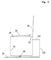
- Fig. 2 shows the side view of a chair or stool (without backrest 26), which has 2 tubular frames 21 on the left and right of the seat part 20 as a support structure.
- the seat surface, not shown, is rectangular.
- the support structure stands on the axis of rotation 23, which rests, for example, on a base, the floor 24.
- This axis of rotation 23 can be designed as a rod with a round, semicircular or angular cross section. It has been shown that a rod with a diameter of 10-20 mm enables a comfortable movement of the seat.
- the rod can be firmly connected to the seating furniture or can lie loosely on the floor or even under a cover (eg carpet or rubber mat).
- the rod or the axis of rotation can also be part of a foundation construction or a joint, not shown.
- Sitting in the middle position can be perceived as pleasant.
- a fit that fits the body and is padded with a thin cushion has proven itself.
- relaxation takes longer when sitting by leaning back against an existing backrest.
- the relaxing "curvature of the spine to the rear" in the area of the lumbar vertebrae is achieved by moving the seat part forward.
- the movement mechanism is therefore contrary to the movement used to date. This can also result in contact with the backrest 26, specifically with the upper edge of the backrest.
- the pleasantly relaxing "curvature of the spine" is enhanced.
- the seat surface can therefore also be movably supported on a curve or straight line as a support which enables a comparable movement of the seat part.
- FIG. 3 This type of storage is shown in Fig. 3 and will now be described.
- the selected representation is a side view.
- the movable seat part 37 rests on a chair base 30 with the rollers 31.
- the height is adjusted via the vertical support 32.
- the frame 33 is height-adjustable and optionally rotatably mounted on this vertical strut 32.
- the circular slide curve 34 is fastened on the frame 33, on which the seat part is guided when the seat part moves.
- the seat part 37 rests on the struts 35 and 36 as parts of the support structure.
- the bevel of the seat part indicates that the angle of the seat part, as shown in Fig. 2, can be adjusted.
- the seat part and the person sitting on it can slide forward and backward along the curve 34 when the seat part moves.
- the amplitude of this movement is approx. 5 cm.
- the entire circular curve 34 is therefore not required as a support for the seat part, but only corresponding supports 40 under the supports 35 and 36.
- These shorter curves 38 and 39 are drawn here as the tangents to the circular curve 34.
- the slope of curves 38 and 39 and the type of curve e.g. Circular arc, ellipse, parabola ... can be varied depending on which movement characteristics are desired.
- it makes sense to reset the seat movement e.g. to be provided in the form of a spring.
- the image also contains a backrest 41 and the corresponding armrests 42.
- the backrest 41 and the armrests 42 are firmly connected to the frame 33 here. Since the effort required to move the seat part with the legs is generally less than the pushing forces required to adjust the roller / swivel chair, the chair can be moved via body contact with the fixed backrests.
- This type of sitting is particularly advantageous for professional activities that require power transmission with the arms (such as assembly line assembly or mechanical processing of workpieces).
- the seating furniture in coordination with the bodily functions of the seated person, enables a seating technique that enables active sitting (no passive rest).
- Example of seating furniture according to FIG. 2 lateral length of the frame 21 47 cm Diameter of the axis of rotation 23 1.6 cm Seat height 46 cm amplitude 5 cm
- Type of seat part flat metal shell (like on a combine or agricultural tractor) padded with pillows.
- the plate extends from the axis of rotation 23 to the right up to the protection 22 against tipping. This construction enables static sitting on a seat part secured against tipping and active sitting in the middle position by moving the seat part forward.
- the height of the seat part can be made adjustable.
Landscapes
- Special Chairs (AREA)
- Chair Legs, Seat Parts, And Backrests (AREA)
- Orthopedics, Nursing, And Contraception (AREA)
- Chairs Characterized By Structure (AREA)
Claims (18)
- Siège pour s'asseoir dans la position centrale, comportant une partie de siège (6,20,37), ainsi qu'une construction d'appui (7,21,35,36) pour la partie de siège, les deux parties fixées pouvant tourner autour d'un axe de rotation (8,23) qui s'étend au-dessous de la partie de siège, dans la zone du fond, transversalement à la direction de siège,
caractérisé en ce que :- la partie de siège (6,20,37) peut être tournée, à partir de l'état de la position centrale possible d'une personne assise, sans moyen de limitation, autour de l'axe de rotation (8,23),- la profondeur de la partie de siège (6,20,37) est telle en direction de siège, vers les deux faces de l'axe de rotation (8,23) que, d'une part :- lors d'une rotation de la partie de siège (6,20,37) de la position centrale vers l'avant, par le poids du corps d'une personne (1,2,3,4,5,9,11), en raison de l'action d'une force de retour (14) derrière l'axe de rotation (8,23), sur la face de siège de la partie de siège (6,20,37), un moment stabilisant agit autour de l'axe de rotation (8), pour le retour de la partie de siège (6,20,37) dans la position initiale, et d'autre part :- lors d'une rotation de la partie de siège de la position centrale vers l'arrière, par le poids du corps d'une personne, en raison de l'action d'une force de retour (15), devant l'axe de rotation (8,23) sur la face de siège de la partie de siège (6,20,37), un moment stabilisant agit autour de l'axe de rotation (8), pour le retour de la partie de siège (6,20,37) dans la position initiale. - Siège selon la revendication 1,
caractérisé en ce que la construction d'appui prend appui sur l'axe de rotation. - Siège selon la revendication 1,
caractérisé en ce que l'axe de rotation est formé par une tige continue ou des pièces partielles de celle-ci. - Siège selon l'une ou plusieurs des revendications précédentes,
caractérisé en ce que l'axe de rotation est une partie de la construction d'appui. - Siège selon l'une ou plusieurs des revendications précédentes,
caractérisé en ce que l'axe de rotation est monté, de façon rotative, dans un palier fixe et la construction d'appui peut tourner autour du centre d'axe. - Siège selon l'une ou plusieurs des revendications précédentes,
caractérisé en ce que l'axe de rotation repose sur un support de façon à pouvoir rouler et la partie de siège peut tourner sur le support, par un mouvement de roulement de l'axe. - Siège selon l'une ou plusieurs des revendications précédentes,
caractérisé en ce que la construction d'appui est constituée de plusieurs cadres, parallèles à la direction de siège. - Siège selon l'une ou plusieurs des revendications précédentes,
caractérisé en ce que les cadres sont montés de façon mobile sur un axe rigide ou des parties de celui-ci et la partie de siège peut tourner, par un roulement sur le profil d'axe, vers l'avant et l'arrière. - Siège selon l'une ou plusieurs des revendications précédentes,
caractérisé en ce que l'axe ou des parties de celui-ci sont fixés sur le sol. - Siège selon l'une ou plusieurs des revendications précédentes,
caractérisé en ce que l'axe de rotation est monté dans le pied du siège. - Siège selon l'une ou plusieurs des revendications précédentes,
caractérisé en ce que l'axe de rotation est formé, en direction de siège, par le bord avant du pied du siège et la partie de siège est montée, au-dessus de la construction d'appui, sur le pied du siège de sorte que, dans la position centrale, lorsque l'on s'assoit, la partie restante du pied du siège est tournée autour de l'axe de rotation vers le haut. - Siège selon l'une ou plusieurs des revendications précédentes,
caractérisé en ce que la construction d'appui est réalisée, de façon à pouvoir être réglée en hauteur, au moyen d'un ressort à gaz sous pression. - Siège selon l'une ou plusieurs des revendications précédentes,
caractérisé en ce que la partie de siège est montée avec la construction d'appui sur des rails de guidage ou des segments de ces derniers, de façon à pouvoir être déplacée vers l'avant et vers l'arrière. - Siège selon l'une ou plusieurs des revendications précédentes,
caractérisé en ce que les rails de guidage sont formés de segments d'arcs de cercle autour de l'axe de rotation. - Siège selon l'une ou plusieurs des revendications précédentes,
caractérisé en ce que les rails de guidage sont montés, de façon à pouvoir être réglés en hauteur, dans le pied du siège. - Siège selon l'une ou plusieurs des revendications précédentes,
caractérisé en ce que la partie de siège peut tourner sur la construction d'appui autour d'un axe, parallèle à l'axe de rotation et peut être fixée par un élément d'arrêt, pour fixer l'inclinaison convenant à la personne de la face de siège dans la position centrale. - Siège selon l'une ou plusieurs des revendications précédentes,
caractérisé en ce qu'une partie de dos est fixée sur la partie de siège et la partie de dos peut être réglée de sorte que, lors d'un mouvement de la partie de siège vers l'avant, justement une partie du dos peut être inclinée vers l'arrière, au-dessus du bord supérieur de la partie de dos. - Siège selon l'une ou plusieurs des revendications précédentes,
caractérisé en ce que la partie de siège peut prendre appui à chaque fois, au moyen d'une butée, contre un basculement vers l'arrière et/ou vers l'avant.
Applications Claiming Priority (3)
| Application Number | Priority Date | Filing Date | Title |
|---|---|---|---|
| DE4134594 | 1991-10-18 | ||
| DE4134594 | 1991-10-18 | ||
| US5569393A | 1993-04-20 | 1993-04-20 |
Publications (2)
| Publication Number | Publication Date |
|---|---|
| EP0543151A1 EP0543151A1 (fr) | 1993-05-26 |
| EP0543151B1 true EP0543151B1 (fr) | 1997-05-14 |
Family
ID=45470736
Family Applications (1)
| Application Number | Title | Priority Date | Filing Date |
|---|---|---|---|
| EP92117769A Expired - Lifetime EP0543151B1 (fr) | 1991-10-18 | 1992-10-16 | Siège d'équilibrage postural |
Country Status (3)
| Country | Link |
|---|---|
| US (1) | US5599061A (fr) |
| EP (1) | EP0543151B1 (fr) |
| DE (1) | DE4201187C2 (fr) |
Cited By (1)
| Publication number | Priority date | Publication date | Assignee | Title |
|---|---|---|---|---|
| EP2543281A1 (fr) | 2011-07-04 | 2013-01-09 | Hans Roericht | Chaise et meuble pour station debout |
Families Citing this family (1)
| Publication number | Priority date | Publication date | Assignee | Title |
|---|---|---|---|---|
| FR2748916B1 (fr) * | 1996-05-23 | 1998-07-03 | Mathou Marcel | Siege comportant des organes de basculement |
Family Cites Families (32)
| Publication number | Priority date | Publication date | Assignee | Title |
|---|---|---|---|---|
| DE7245423U (de) * | 1973-09-13 | Neumueller K U S Metallwaren Ohg | Sitzmöbel, dessen einzelne Bauteile vorzugsweise aus Metall gefertigt sind | |
| US1358640A (en) * | 1920-07-15 | 1920-11-09 | Spady S Koyama | Ship's chair |
| US1437848A (en) * | 1921-09-10 | 1922-12-05 | Kisor Lorenz | Seat for farm machinery |
| US2280732A (en) * | 1940-01-31 | 1942-04-21 | Thum Martin | Convertible rocking chair |
| US2311384A (en) * | 1940-04-10 | 1943-02-16 | Julia C Harpstrite | Roller rocker |
| US2631652A (en) * | 1949-04-19 | 1953-03-17 | Le Roy D Bannister | Portable milking stool |
| US3014686A (en) * | 1957-04-11 | 1961-12-26 | Golden | Transportation chair |
| CH417882A (de) * | 1964-07-01 | 1966-07-31 | Haas Arthur | Fussgestell zur wiegenden Aufnahme eines Sitzes oder einer Liege |
| US3306658A (en) * | 1966-03-08 | 1967-02-28 | Charles T Roberts | Contoured body rest |
| DE1554179C3 (de) * | 1966-12-13 | 1974-07-04 | Curt 7200 Tuttlingen Wekerle | Kippschaukel mit einem feststehenden Fußgestell |
| DE1812360A1 (de) * | 1968-12-03 | 1970-06-18 | Rollei Werke Franke Heidecke | Rollfilmkamera fuer perforierten Rollfilm |
| US3784148A (en) * | 1972-05-15 | 1974-01-08 | B Hill | Rocker base |
| US3891270A (en) * | 1974-05-10 | 1975-06-24 | Krueger Metal Products | Pneumatic stool with foot rest connected to seat base |
| US4236752A (en) * | 1979-05-04 | 1980-12-02 | Hoover Universal, Inc. | Rocker swivel assembly for chairs |
| US4451080A (en) * | 1981-02-27 | 1984-05-29 | Ceoma Nix | Mobility aid |
| US4411468A (en) * | 1981-03-05 | 1983-10-25 | Homecrest Industries Incorporated | Rocking chair |
| US4534591A (en) * | 1982-10-12 | 1985-08-13 | Parker Michael S | Controlled rocking action furniture |
| CA1235646A (fr) * | 1983-04-29 | 1988-04-26 | Peter Opsvik | Dispositif d'assise |
| US4544200A (en) * | 1983-06-02 | 1985-10-01 | Philip Dunn | Wheelchair with rocking seat and reclining back feature |
| FR2569965A1 (fr) * | 1983-08-03 | 1986-03-14 | Dourisboure Maurice | Siege-terrasse |
| FR2561510B1 (fr) * | 1984-03-21 | 1987-03-06 | Lehmans Jean Michel | Dispositif d'equilibrage postural ergonomique et de soutien pour le corps humain, notamment un siege a calage variable ischio-lombaire |
| US4738487A (en) * | 1984-05-22 | 1988-04-19 | Ergoform Inc. | Tilting seat |
| DE3421550A1 (de) * | 1984-06-06 | 1985-12-12 | Schwebel, Thomas, 6500 Mainz | Sitzgeraet, insbesondere stuhl, zum kippeln |
| US4641848A (en) * | 1985-04-15 | 1987-02-10 | Ayers Robert C | Wheelchair with rocking seat assembly |
| DE3519673A1 (de) * | 1985-06-01 | 1986-12-04 | B. u. W. Schmidt GmbH & Co KG, 3008 Garbsen | Neigungsverstellbarer sitz fuer koerperbehinderte u. dgl. |
| FR2642284B1 (fr) * | 1989-01-27 | 1991-05-10 | Grasset Michel | Siege ergonomique reglable permettant de s'asseoir en appui sur les genoux |
| DE3902694A1 (de) * | 1989-01-30 | 1990-08-02 | Ortopedia Gmbh | Rollstuhl mit verstellbarem sitz |
| CH678388A5 (fr) * | 1989-04-25 | 1991-09-13 | Hugo Degen | |
| SU1676622A1 (ru) * | 1989-05-30 | 1991-09-15 | А.В,Кон хин | Инвалидна кол ска |
| DE3921384C1 (fr) * | 1989-06-29 | 1991-02-14 | Erfi Produktions-Gmbh & Co Kg, 8637 Ahorn, De | |
| US5048893A (en) * | 1990-07-16 | 1991-09-17 | Benjamin Cowan | Ergonomic chair |
| DE9012189U1 (de) * | 1990-08-24 | 1990-10-25 | MEYRA Wilhelm Meyer GmbH & Co KG, 4925 Kalletal | Rollstuhl |
-
1992
- 1992-01-18 DE DE4201187A patent/DE4201187C2/de not_active Expired - Fee Related
- 1992-10-16 EP EP92117769A patent/EP0543151B1/fr not_active Expired - Lifetime
-
1995
- 1995-05-12 US US08/439,760 patent/US5599061A/en not_active Expired - Fee Related
Cited By (2)
| Publication number | Priority date | Publication date | Assignee | Title |
|---|---|---|---|---|
| EP2543281A1 (fr) | 2011-07-04 | 2013-01-09 | Hans Roericht | Chaise et meuble pour station debout |
| DE102011122094A1 (de) | 2011-07-04 | 2013-01-10 | Hans Roericht | Stuhl und Stehsitz-Möbel |
Also Published As
| Publication number | Publication date |
|---|---|
| DE4201187C2 (de) | 2001-12-13 |
| US5599061A (en) | 1997-02-04 |
| DE4201187A1 (de) | 1993-04-22 |
| EP0543151A1 (fr) | 1993-05-26 |
Similar Documents
| Publication | Publication Date | Title |
|---|---|---|
| DE69928538T2 (de) | Stuhl | |
| DE202011050776U1 (de) | Elastische lehnpositions-wiederherstellungsvorrichtung für eine höhenverstellbare rückenlehne eines bürostuhls | |
| DE3537028A1 (de) | Stuhl | |
| DE2820063A1 (de) | Stuhl | |
| DE1117274B (de) | Dem menschlichen Koerper angepasster Sitz | |
| AT398160B (de) | Arbeitssessel, insbesondere bürosessel | |
| DE3321488C2 (de) | Stuhl | |
| DE60316129T2 (de) | Ergonomisches sitzmodul und sitz mit einem solchen modul | |
| AT509545A1 (de) | Sitzmöbel mit verschwenkbaren armlehnen | |
| EP3476254B1 (fr) | Siège, en particulier chaise de bureau | |
| DE69622204T2 (de) | Stuhl | |
| DE2344534A1 (de) | Transportable rueckenstuetze | |
| DE1480188A1 (de) | Kraftfahrzeugsitz | |
| EP0543151B1 (fr) | Siège d'équilibrage postural | |
| DE102013110674B3 (de) | Therapeutischer Bürodrehstuhl | |
| EP3193670B1 (fr) | Meuble pourvu d'un dispositif de pivotement destiné à un élément pivotant | |
| EP1774871A1 (fr) | Dispositif pour ajuster un meuble d'assise au poids corporel et centre de gravité d'une personne | |
| DE3519673A1 (de) | Neigungsverstellbarer sitz fuer koerperbehinderte u. dgl. | |
| DE4328679C2 (de) | Stuhl, insbesondere zahnärztlicher Arbeitsstuhl | |
| DE2732193B1 (de) | Sitz- und Liegemoebel aus mehreren klappbaren Polsterteilen | |
| DE2856177A1 (de) | Als gymnastikgeraet wirkender sitz | |
| DE102013003746A1 (de) | Stuhl, Krafttrainingsgerät und Verwendung eines Stuhls als Krafttrainingsgerät | |
| DE2418125A1 (de) | Vorrichtung zum sitzen | |
| DE8912125U1 (de) | Sitzmöbel, insbesondere Stuhl | |
| EP4154858A1 (fr) | Siège doté d'une aide à la levage |
Legal Events
| Date | Code | Title | Description |
|---|---|---|---|
| PUAI | Public reference made under article 153(3) epc to a published international application that has entered the european phase |
Free format text: ORIGINAL CODE: 0009012 |
|
| AK | Designated contracting states |
Kind code of ref document: A1 Designated state(s): AT BE CH DE DK ES FR GB GR IT LI LU MC NL PT SE |
|
| 17P | Request for examination filed |
Effective date: 19930622 |
|
| RBV | Designated contracting states (corrected) |
Designated state(s): CH DE FR GB IT LI SE |
|
| 17Q | First examination report despatched |
Effective date: 19950210 |
|
| GRAG | Despatch of communication of intention to grant |
Free format text: ORIGINAL CODE: EPIDOS AGRA |
|
| GRAH | Despatch of communication of intention to grant a patent |
Free format text: ORIGINAL CODE: EPIDOS IGRA |
|
| GRAH | Despatch of communication of intention to grant a patent |
Free format text: ORIGINAL CODE: EPIDOS IGRA |
|
| GRAA | (expected) grant |
Free format text: ORIGINAL CODE: 0009210 |
|
| AK | Designated contracting states |
Kind code of ref document: B1 Designated state(s): CH DE FR GB IT LI SE |
|
| REG | Reference to a national code |
Ref country code: CH Ref legal event code: EP |
|
| REF | Corresponds to: |
Ref document number: 59208488 Country of ref document: DE Date of ref document: 19970619 |
|
| GBT | Gb: translation of ep patent filed (gb section 77(6)(a)/1977) |
Effective date: 19970722 |
|
| EN | Fr: translation not filed | ||
| PG25 | Lapsed in a contracting state [announced via postgrant information from national office to epo] |
Ref country code: FR Effective date: 19971010 |
|
| EN | Fr: translation not filed |
Free format text: BO 97/41 PAGES 227, LA MENTION DE LA NON REMISE DE CETTE TRADUCTION.LA MENTION DE LA REMISE DE CETTE TRADUCTION EST PUBLIEE DANS LE PRECENT BOPI |
|
| ET | Fr: translation filed | ||
| PLBE | No opposition filed within time limit |
Free format text: ORIGINAL CODE: 0009261 |
|
| STAA | Information on the status of an ep patent application or granted ep patent |
Free format text: STATUS: NO OPPOSITION FILED WITHIN TIME LIMIT |
|
| 26N | No opposition filed | ||
| PGFP | Annual fee paid to national office [announced via postgrant information from national office to epo] |
Ref country code: SE Payment date: 20001020 Year of fee payment: 9 |
|
| PG25 | Lapsed in a contracting state [announced via postgrant information from national office to epo] |
Ref country code: SE Free format text: LAPSE BECAUSE OF NON-PAYMENT OF DUE FEES Effective date: 20011017 |
|
| PGFP | Annual fee paid to national office [announced via postgrant information from national office to epo] |
Ref country code: GB Payment date: 20011026 Year of fee payment: 10 Ref country code: FR Payment date: 20011026 Year of fee payment: 10 |
|
| PGFP | Annual fee paid to national office [announced via postgrant information from national office to epo] |
Ref country code: CH Payment date: 20011031 Year of fee payment: 10 |
|
| REG | Reference to a national code |
Ref country code: GB Ref legal event code: IF02 |
|
| EUG | Se: european patent has lapsed |
Ref document number: 92117769.7 |
|
| PG25 | Lapsed in a contracting state [announced via postgrant information from national office to epo] |
Ref country code: GB Free format text: LAPSE BECAUSE OF NON-PAYMENT OF DUE FEES Effective date: 20021016 |
|
| PG25 | Lapsed in a contracting state [announced via postgrant information from national office to epo] |
Ref country code: LI Free format text: LAPSE BECAUSE OF NON-PAYMENT OF DUE FEES Effective date: 20021031 Ref country code: CH Free format text: LAPSE BECAUSE OF NON-PAYMENT OF DUE FEES Effective date: 20021031 |
|
| GBPC | Gb: european patent ceased through non-payment of renewal fee |
Effective date: 20021016 |
|
| REG | Reference to a national code |
Ref country code: CH Ref legal event code: PL |
|
| REG | Reference to a national code |
Ref country code: FR Ref legal event code: ST |
|
| PGFP | Annual fee paid to national office [announced via postgrant information from national office to epo] |
Ref country code: DE Payment date: 20051031 Year of fee payment: 14 |
|
| PGFP | Annual fee paid to national office [announced via postgrant information from national office to epo] |
Ref country code: IT Payment date: 20061031 Year of fee payment: 15 |
|
| PG25 | Lapsed in a contracting state [announced via postgrant information from national office to epo] |
Ref country code: DE Free format text: LAPSE BECAUSE OF NON-PAYMENT OF DUE FEES Effective date: 20070501 |
|
| PG25 | Lapsed in a contracting state [announced via postgrant information from national office to epo] |
Ref country code: IT Free format text: LAPSE BECAUSE OF NON-PAYMENT OF DUE FEES Effective date: 20071016 |