EP3193670B1 - Meuble pourvu d'un dispositif de pivotement destiné à un élément pivotant - Google Patents
Meuble pourvu d'un dispositif de pivotement destiné à un élément pivotant Download PDFInfo
- Publication number
- EP3193670B1 EP3193670B1 EP15771062.5A EP15771062A EP3193670B1 EP 3193670 B1 EP3193670 B1 EP 3193670B1 EP 15771062 A EP15771062 A EP 15771062A EP 3193670 B1 EP3193670 B1 EP 3193670B1
- Authority
- EP
- European Patent Office
- Prior art keywords
- chair
- furniture
- seat
- office
- pin
- Prior art date
- Legal status (The legal status is an assumption and is not a legal conclusion. Google has not performed a legal analysis and makes no representation as to the accuracy of the status listed.)
- Active
Links
Images



Classifications
-
- A—HUMAN NECESSITIES
- A47—FURNITURE; DOMESTIC ARTICLES OR APPLIANCES; COFFEE MILLS; SPICE MILLS; SUCTION CLEANERS IN GENERAL
- A47C—CHAIRS; SOFAS; BEDS
- A47C9/00—Stools for specified purposes
- A47C9/002—Stools for specified purposes with exercising means or having special therapeutic or ergonomic effects
-
- A—HUMAN NECESSITIES
- A47—FURNITURE; DOMESTIC ARTICLES OR APPLIANCES; COFFEE MILLS; SPICE MILLS; SUCTION CLEANERS IN GENERAL
- A47C—CHAIRS; SOFAS; BEDS
- A47C1/00—Chairs adapted for special purposes
- A47C1/02—Reclining or easy chairs
- A47C1/022—Reclining or easy chairs having independently-adjustable supporting parts
- A47C1/024—Reclining or easy chairs having independently-adjustable supporting parts the parts, being the back-rest, or the back-rest and seat unit, having adjustable inclination
- A47C1/0242—Reclining or easy chairs having independently-adjustable supporting parts the parts, being the back-rest, or the back-rest and seat unit, having adjustable inclination by electric motors
-
- A—HUMAN NECESSITIES
- A47—FURNITURE; DOMESTIC ARTICLES OR APPLIANCES; COFFEE MILLS; SPICE MILLS; SUCTION CLEANERS IN GENERAL
- A47C—CHAIRS; SOFAS; BEDS
- A47C1/00—Chairs adapted for special purposes
- A47C1/02—Reclining or easy chairs
- A47C1/031—Reclining or easy chairs having coupled concurrently adjustable supporting parts
- A47C1/032—Reclining or easy chairs having coupled concurrently adjustable supporting parts the parts being movably-coupled seat and back-rest
-
- A—HUMAN NECESSITIES
- A47—FURNITURE; DOMESTIC ARTICLES OR APPLIANCES; COFFEE MILLS; SPICE MILLS; SUCTION CLEANERS IN GENERAL
- A47C—CHAIRS; SOFAS; BEDS
- A47C1/00—Chairs adapted for special purposes
- A47C1/02—Reclining or easy chairs
- A47C1/031—Reclining or easy chairs having coupled concurrently adjustable supporting parts
- A47C1/032—Reclining or easy chairs having coupled concurrently adjustable supporting parts the parts being movably-coupled seat and back-rest
- A47C1/03255—Reclining or easy chairs having coupled concurrently adjustable supporting parts the parts being movably-coupled seat and back-rest with a central column, e.g. rocking office chairs
-
- A—HUMAN NECESSITIES
- A47—FURNITURE; DOMESTIC ARTICLES OR APPLIANCES; COFFEE MILLS; SPICE MILLS; SUCTION CLEANERS IN GENERAL
- A47C—CHAIRS; SOFAS; BEDS
- A47C3/00—Chairs characterised by structural features; Chairs or stools with rotatable or vertically-adjustable seats
- A47C3/02—Rocking chairs
- A47C3/025—Rocking chairs with seat, or seat and back-rest unit, elastically mounted in a rigid frame
- A47C3/0255—Rocking chairs with seat, or seat and back-rest unit, elastically mounted in a rigid frame pivotally mounted in the base frame, e.g. swings
-
- A—HUMAN NECESSITIES
- A47—FURNITURE; DOMESTIC ARTICLES OR APPLIANCES; COFFEE MILLS; SPICE MILLS; SUCTION CLEANERS IN GENERAL
- A47C—CHAIRS; SOFAS; BEDS
- A47C3/00—Chairs characterised by structural features; Chairs or stools with rotatable or vertically-adjustable seats
- A47C3/02—Rocking chairs
- A47C3/025—Rocking chairs with seat, or seat and back-rest unit, elastically mounted in a rigid frame
- A47C3/026—Rocking chairs with seat, or seat and back-rest unit, elastically mounted in a rigid frame with a central column, e.g. rocking office chairs; Tilting chairs
-
- A—HUMAN NECESSITIES
- A47—FURNITURE; DOMESTIC ARTICLES OR APPLIANCES; COFFEE MILLS; SPICE MILLS; SUCTION CLEANERS IN GENERAL
- A47C—CHAIRS; SOFAS; BEDS
- A47C9/00—Stools for specified purposes
- A47C9/002—Stools for specified purposes with exercising means or having special therapeutic or ergonomic effects
- A47C9/005—Stools for specified purposes with exercising means or having special therapeutic or ergonomic effects with forwardly inclined seat, e.g. with a knee-support
Definitions
- the invention relates to a piece of furniture with a pivotable part, namely an office chair or armchair or kneeling chair, in particular for use in connection with training or games in a virtual reality environment, according to the preamble of claim 1 and similar to the DE 199 15 003 .
- Office chairs have a seat and a backrest above a height-adjustable support part, which is considered to be part of the chassis in this application, which can be rotated together about a common vertical axis, usually the vertical axis of the support part, and can each be pivoted about at least one horizontal axis individually or in dependence on one another.
- a height-adjustable support part which is considered to be part of the chassis in this application, which can be rotated together about a common vertical axis, usually the vertical axis of the support part, and can each be pivoted about at least one horizontal axis individually or in dependence on one another.
- the aim of the invention is to provide a mechanism that meets these conditions in a simple, cost-effective and mechanically stable manner.
- the mobility should be able to be limited in a variety of ways, especially to give the user the opportunity to act on their urge to move (e.g. children with ADHD).
- the movement should be dictated from the outside. This is particularly important in connection with game consoles or simulation situations using "virtual reality” (VR) in the form of VR glasses or VR helmets, etc. This can also be beneficial in the medical field to make it easier to move patients, to vary the lying surfaces of patients to prevent bedsores, etc.
- VR virtual reality
- a horizontal axis for pivoting the seat is provided on a height-adjustable support part and a series of three arms arranged in series that can pivot relative to one another is formed on the seat, the last of which is firmly connected to the backrest and whose three pivot axes intersect one another at one point.
- This point is preferably in the pelvic area of the presumed user, preferably approximately at the level of the user's center of gravity.
- the moving part moves around an instantaneous center that is not fixed to the base. In many applications (normal office chairs, etc.) this is sufficient, but in other applications, for example in the medical field or But when used in conjunction with VR, a common intersection point is highly desirable, if not necessary.
- a four-bar linkage (without reference number) visible below this construction establishes the statically determined position and can, if necessary, be used to regulate the inclination of the seat surface in the rest position.
- the seat axis 17 is stationary with respect to the seat surface 5, but not with respect to the supporting part 2, to which it is articulated via the struts 15 and the wing 22.
- a base part 6 At the rear of the seat 5 (basic furniture part) there is a base part 6 ( Fig. 2 ) is firmly mounted.
- An intermediate part 7 is mounted on the base part 6 so that it can rotate around a base axis
- a second arm 8 is mounted on the intermediate part 7 so that it can rotate
- a backrest part 9 is mounted on this, also rotatable.
- the invention provides that the axes of rotation between the base part and the intermediate part 7, between the intermediate part 7 and the second arm 8, and between the second arm 8 and the backrest part 9 intersect at a central point 10.
- the backrest 11 in furniture in general, corresponding to the swivel furniture part
- This mechanism now achieves a previously unattainable mobility around this central point 10, and thus also around three Cartesian axes (or axes parallel to it) that are not physically formed, but are drawn with their origin at the central point 10. These are the vertical axis Z, the transverse axis Q and the longitudinal axis L. In the individual embodiments shown, the respective locking of the pivoting around one or two of these axes is achieved by various measures that are simple and robust and, with knowledge of the invention, can also be easily combined with one another.
- a mechanism is also provided, which is not necessarily used, for creating a counterforce when leaning backwards: between a seat surface 18 on the underside of the seat surface 5 and a mostly curved fin surface 19 on the fin 12, a spacer rod 20 is clamped with a roller 21 at the upper and lower ends. Its current position is determined by its guidance in a guide opening 23 in the second arm 8 (see also Fig. 3 ). It may also protrude through another, but correspondingly larger, through-opening (not shown) in the backrest part 9, but its position is not affected by this, as this only occurs through the guide opening 23.
- the spacer rod 20 is guided in this guide opening 23 so that it can be moved longitudinally but not rotated, so that it always rolls at the correct angle along the running surfaces 18, 19 with its rollers 21.
- the guide opening 23 shifts/twists and takes the spacer rod 20 with it, subjecting it to bending, the weight of the user, pivotably mounted about the seat axis 17, presses against the backrest part 9 via the spacer rod 20 and the guide opening 23 against leaning back.
- other such mechanisms known from the prior art can be used, but this one, with its compact design and the shape of the fin running surface 19 which can easily be adapted to different designs, is particularly suitable for combination with the pivoting mechanism according to the invention.
- the support part 2 has a fin 12 running in the longitudinal direction L, which can of course also be designed differently; in the embodiment shown, it serves to fix the rotation about the axis L and the axis Q, and this in the following way:
- a pin 14 possibly provided with a roller, or spring-mounted, etc.
- the backrest part 9 projects into the fin 12, which in this case is designed with a groove 12', and thus prevents rotation about the longitudinal axis L.
- no further axial fixation occurs.
- Fig. 5 a variant in which rotation around the vertical axis Z is blocked, but in return, as is often desired in office chairs used for gymnastics, rotation around the transverse axis Q as well as around the longitudinal axis L is possible: This is achieved by comparing the Fig. 3 shows that the fin 12 is not fixedly connected to the supporting part 2 (not shown), but via a parallel guide by means of two joint parallelograms 13.
- This embodiment has the advantage that the actual attachment to the supporting part 2, the shape of which can be chosen very freely, can vary within wide limits.
- this variant is often advantageously used in particular for other furniture, for example loungers and folding beds.
- the Fig. 7 shows, in the form of an exploded diagram, the more precise design of the individual components of the mechanism according to the invention, the base part 6, the intermediate part 7, the second arm 8 including the guide opening 23 and the backrest part 9, again with the rib indicating the backrest 11.
- the ring-shaped design creates a compact and mechanically extremely stable construction that is able to safely transmit the large forces caused by the short lever arms. Also shown are details of the bearing design such as circlips and roller bearings, these can be provided in many different forms.
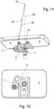
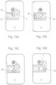
- gate opening 30 and the pin 14 are in Fig. 10 and Fig. 14 clearly recognizable, in the description and the claims, the component having the gate opening 30 is itself casually referred to as "gate opening 30".
- Fig. 14 shows a perspective bottom view of a variant of the invention, from which it can be clearly seen that the kinematics with its two arms between the end parts can be provided in a very flat manner and does not require more space than usual kinematics of swivel chairs, etc. according to the prior art.
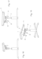
- Figs. 15, 16 and 17 show, purely schematically (without backrest, without armrest, without footrest, without power lines, without control lines, without central control element, without safety covers, etc., etc.), the attachment of motors 31, 32 and 33 directly to the swivel axes 24, 25 and 26 between the serially arranged components 5/7 (24), 7/8 (25) and 8/2 (26). Whether a link restricting mobility is also provided in such an arrangement is a question of safety philosophy and is not causally related to the invention.
- the invention is not limited to the examples shown; the shapes and dimensions of the components base part - intermediate part - second arm - backrest part can have other shapes and dimensions and can be constructed completely differently in other pieces of furniture, provided that the axes of rotation defined between them only intersect at one point, the central point 10.
Landscapes
- Health & Medical Sciences (AREA)
- Dentistry (AREA)
- General Health & Medical Sciences (AREA)
- Chairs For Special Purposes, Such As Reclining Chairs (AREA)
- Special Chairs (AREA)
- Chairs Characterized By Structure (AREA)
Claims (17)
- Meuble comprenant un élément de meuble de base et un élément de meuble pivotant monté de façon pivotante sur celui-ci à l'aide d'un mécanisme de pivotement, ledit mécanisme de pivotement comportant un système cinématique (34) grâce auquel l'élément de meuble pivotant peut exécuter un mouvement sphérique par rapport à l'élément de meuble de base, autour d'un centre momentané de rotation situé au-dessus de l'élément de meuble de base, le système cinématique (34) comprenant au moins un bras de base (8), disposé sur l'élément de meuble de base avec possibilité de pivotement par l'intermédiaire d'un axe de base (26), et un bras intermédiaire (7) qui est disposé de manière pivotante (25) sur ledit bras de base et est également monté avec possibilité de pivotement (24) sur l'élément de meuble de base, étant précisé que les trois axes de pivotement (24, 25, 26) présentent leur plus petit espacement au-dessus de l'élément de meuble de base.
- Meuble selon la revendication 1, caractérisé en ce que le centre instantané de rotation est un point central (10) fixe de la base.
- Meuble selon la revendication 1 et 2, caractérisé en ce que les trois axes de pivotement (24, 25, 26) se coupent toujours en un point, à savoir le point central (10).
- Meuble selon une des revendications 1 à 3, caractérisé en ce qu'il s'agit d'un fauteuil, notamment d'un fauteuil de bureau (1), et que son élément de meuble de base est une surface d'assise (5) et l'élément de meuble pivotant est un dossier (11) du fauteuil.
- Fauteuil, notamment fauteuil de bureau (1) selon la revendication 4, comprenant un châssis (3) doté d'un élément de support (2) auquel est fixée la surface d'assise (5), le cas échéant avec possibilité de pivotement, caractérisé en ce qu'un élément de base (6) est disposé sur la face inférieure de la surface d'assise (5), derrière la fixation de l'élément de support (2).
- Fauteuil, notamment fauteuil de bureau (1) selon la revendication 4 ou 5, caractérisé en ce que l'élément de support (2) présente un aileron (12) qui est orienté vers l'arrière et en ce que l'élément pivotant (9) est guidé de manière fixe en rotation sur cet aileron. (Fig. 3)
- Fauteuil, notamment fauteuil de bureau (1) selon la revendication 4 ou 5, caractérisé en ce que l'élément de support (2) présente un aileron (12) qui est orienté vers l'arrière et comporte une rainure longitudinale (12'), et en ce que l'élément pivotant (9) est guidé avec possibilité de rotation dans la rainure (12'). (Fig. 4)
- Fauteuil, notamment fauteuil de bureau (1) selon la revendication 4 ou 5, caractérisé en ce que l'élément de support (2) présente un aileron (12) qui est orienté vers l'arrière, que cet aileron est monté avec possibilité de déplacement parallèle à lui-même, dans le sens de l'axe transversal (Q), et en ce que l'élément pivotant (9) est guidé de manière fixe en rotation sur cet aileron. (Fig. 5)
- Fauteuil, notamment fauteuil de bureau (1) selon une des revendications 4 à 8, caractérisé en ce qu'il est prévu, sur la face inférieure de la surface d'assise (5), une surface de déplacement de siège (18) et, sur l'aileron (12), une surface de déplacement d'aileron (19), en ce qu'il est prévu entre ces surfaces de déplacement, une tige d'espacement (20) dotée de galets (21) à ses extrémités, dont les galets roulent sur les surfaces de déplacement, et en ce que la tige d'espacement (20) est guidée dans une ouverture de guidage (23) dans le bras secondaire (8), avec possibilité de déplacement longitudinal mais de manière fixe en rotation.
- Fauteuil, notamment fauteuil de bureau (1) selon une des revendications 4 à 9, caractérisé en ce que- soit un tenon (14) est relié à l'élément de support (2) et pénètre dans une ouverture de coulisse (30) qui est reliée à la surface d'assise (5),- soit un tenon (14) est relié à la surface d'assise (5) et pénètre dans une ouverture de coulisse (30) qui est reliée à l'élément de support (2). (Fig. 11)
- Fauteuil, notamment fauteuil de bureau (1) selon la revendication 10, caractérisé en ce que le guide-coulisse (13) ou le tenon (12) est prévu sur un élément de liaison de siège (6) sur lequel est également en prise le système cinématique (34).
- Fauteuil, notamment fauteuil de bureau (1) selon la revendication 11, caractérisé en ce que l'ouverture de coulisse (30) ou le tenon (14) est relié(e) à l'élément de liaison de siège (6), en faisant ressort.
- Fauteuil, notamment fauteuil de bureau (1) selon une des revendications 10 à 12, caractérisé en ce que le tenon (14) porte une bague tournante, le cas échéant de manière à faire ressort radialement, laquelle bague entre en contact avec le bord d'l'ouverture de coulisse (30).
- Fauteuil, notamment fauteuil de bureau (1) selon une des revendications 9 à 12, caractérisé en ce que l'ouverture de coulisse (30) est un guide-coulisse qui présente la forme d'un « 8 ».
- Fauteuil selon une des revendications 4 à 14, caractérisé en ce qu'il est prévu au moins un moteur (31, 32, 33) et/ou une unité moteur-mécanisme de transmission et, le cas échéant, des freins, avec lequel ou laquelle la position angulaire autour d'au moins un des axes de rotation (24, 25, 26) du système cinématique (34) est modifiée et fixée de façon contrôlée.
- Fauteuil selon la revendication 15, caractérisé en ce qu'au moins un moteur (31, 32, 33) ou une unité moteur-mécanisme de transmission est monté(e) sur l'axe (24, 25, 26) associé.
- Fauteuil selon la revendication 15 ou 16, caractérisé en ce qu'au moins un moteur ou une unité moteur-mécanisme de transmission est stationnaire par rapport à la base, et en ce que l'entraînement sur les axes ou arbres s'effectue au moyen de transmissions par courroie, de transmissions par chaîne, de câbles Bowden ou de dispositifs analogues.
Applications Claiming Priority (3)
| Application Number | Priority Date | Filing Date | Title |
|---|---|---|---|
| DE102014013560.8A DE102014013560A1 (de) | 2014-09-18 | 2014-09-18 | Möbel mit Schwenkvorrichtung für einen Schwenkteil |
| ATA50328/2015A AT516286A3 (de) | 2014-09-18 | 2015-04-24 | Stuhl |
| PCT/EP2015/071440 WO2016042127A1 (fr) | 2014-09-18 | 2015-09-18 | Meuble pourvu d'un dispositif de pivotement destiné à un élément pivotant |
Publications (3)
| Publication Number | Publication Date |
|---|---|
| EP3193670A1 EP3193670A1 (fr) | 2017-07-26 |
| EP3193670C0 EP3193670C0 (fr) | 2025-01-22 |
| EP3193670B1 true EP3193670B1 (fr) | 2025-01-22 |
Family
ID=55444270
Family Applications (1)
| Application Number | Title | Priority Date | Filing Date |
|---|---|---|---|
| EP15771062.5A Active EP3193670B1 (fr) | 2014-09-18 | 2015-09-18 | Meuble pourvu d'un dispositif de pivotement destiné à un élément pivotant |
Country Status (4)
| Country | Link |
|---|---|
| EP (1) | EP3193670B1 (fr) |
| AT (1) | AT516286A3 (fr) |
| DE (1) | DE102014013560A1 (fr) |
| PL (1) | PL3193670T3 (fr) |
Families Citing this family (3)
| Publication number | Priority date | Publication date | Assignee | Title |
|---|---|---|---|---|
| CN110022724B (zh) * | 2016-12-20 | 2022-11-11 | 国誉株式会社 | 椅子和椅子的罩构件 |
| EP3476254B1 (fr) | 2017-10-25 | 2021-06-09 | EB-invent GmbH | Siège, en particulier chaise de bureau |
| DE102021104004B4 (de) | 2021-02-19 | 2026-05-07 | Eb-Invent Gmbh | Sitzmöbel |
Citations (13)
| Publication number | Priority date | Publication date | Assignee | Title |
|---|---|---|---|---|
| US3141669A (en) | 1963-04-26 | 1964-07-21 | Chul Yun | Hoop device |
| US4254990A (en) | 1979-03-13 | 1981-03-10 | Kelley Eugene M | Stabilized oscillating chair |
| US4799667A (en) | 1985-08-07 | 1989-01-24 | Gyroteq Corporation | Physical exercise apparatus |
| US5342244A (en) | 1993-01-08 | 1994-08-30 | Nelson Kevin R | Human-powered gyroscope |
| WO1998015382A1 (fr) | 1996-10-05 | 1998-04-16 | Axel Holle | Dispositif de mise en mouvement de corps dans l'espace |
| WO1998016138A1 (fr) | 1996-10-11 | 1998-04-23 | Giroflex Entwicklungs Ag | Siege, notamment siege de bureau |
| DE19915003A1 (de) | 1999-04-01 | 2000-10-05 | Michael Stips | Sitzvorrichtung und Verfahren zu ihrer Steuerung |
| US6988951B1 (en) | 2002-01-23 | 2006-01-24 | Newman Sven D | Floating machine |
| US20060213308A1 (en) | 2005-03-22 | 2006-09-28 | Ross-Hime Designs, Inc. | Robotic manipulator |
| KR100950812B1 (ko) | 2007-11-12 | 2010-04-02 | 김옥근 | 시뮬레이터 |
| WO2012123102A1 (fr) | 2011-03-17 | 2012-09-20 | Eb-Invent Gmbh | Manipulateur |
| WO2014009147A1 (fr) * | 2012-07-11 | 2014-01-16 | Eb-Invent Gmbh | Dispositif de siège |
| US8662586B2 (en) | 2006-10-10 | 2014-03-04 | Hector Serber | Dynamically balanced seat assembly having independently and arcuately movable backrest and method |
-
2014
- 2014-09-18 DE DE102014013560.8A patent/DE102014013560A1/de active Pending
-
2015
- 2015-04-24 AT ATA50328/2015A patent/AT516286A3/de not_active Application Discontinuation
- 2015-09-18 EP EP15771062.5A patent/EP3193670B1/fr active Active
- 2015-09-18 PL PL15771062.5T patent/PL3193670T3/pl unknown
Patent Citations (14)
| Publication number | Priority date | Publication date | Assignee | Title |
|---|---|---|---|---|
| US3141669A (en) | 1963-04-26 | 1964-07-21 | Chul Yun | Hoop device |
| US4254990A (en) | 1979-03-13 | 1981-03-10 | Kelley Eugene M | Stabilized oscillating chair |
| US4799667A (en) | 1985-08-07 | 1989-01-24 | Gyroteq Corporation | Physical exercise apparatus |
| US5342244A (en) | 1993-01-08 | 1994-08-30 | Nelson Kevin R | Human-powered gyroscope |
| US6331152B1 (en) | 1996-10-05 | 2001-12-18 | Axel Holle | Three dimension body movement device |
| WO1998015382A1 (fr) | 1996-10-05 | 1998-04-16 | Axel Holle | Dispositif de mise en mouvement de corps dans l'espace |
| WO1998016138A1 (fr) | 1996-10-11 | 1998-04-23 | Giroflex Entwicklungs Ag | Siege, notamment siege de bureau |
| DE19915003A1 (de) | 1999-04-01 | 2000-10-05 | Michael Stips | Sitzvorrichtung und Verfahren zu ihrer Steuerung |
| US6988951B1 (en) | 2002-01-23 | 2006-01-24 | Newman Sven D | Floating machine |
| US20060213308A1 (en) | 2005-03-22 | 2006-09-28 | Ross-Hime Designs, Inc. | Robotic manipulator |
| US8662586B2 (en) | 2006-10-10 | 2014-03-04 | Hector Serber | Dynamically balanced seat assembly having independently and arcuately movable backrest and method |
| KR100950812B1 (ko) | 2007-11-12 | 2010-04-02 | 김옥근 | 시뮬레이터 |
| WO2012123102A1 (fr) | 2011-03-17 | 2012-09-20 | Eb-Invent Gmbh | Manipulateur |
| WO2014009147A1 (fr) * | 2012-07-11 | 2014-01-16 | Eb-Invent Gmbh | Dispositif de siège |
Non-Patent Citations (9)
| Title |
|---|
| ANONYMOUS: "Technology // Omni-Wrist III ", ROSS-HIME DESIGNS, INC (ACCESSED VIA THE WAYBACK MACHINE), 3 May 2013 (2013-05-03), XP093331422, Retrieved from the Internet <URL:https://web.archive.org/web/20130503001555/http://www.anthrobot.com/omni_III_pla tform> |
| ANONYMOUS: "Technology // Omni-Wrist III", ROSS-HIME DESIGNS, INC (ACCESSED VIA THE WAYBACK MACHINE), 2 May 2013 (2013-05-02), XP093331428, Retrieved from the Internet <URL:https://web.archive.org/web/20130502225100/http:/www.anthrobot.com/omni_III/> |
| BAI SHAOPING, HANSEN MICHAEL R., ANDERSEN TORBEN O.: "Modelling of a special class of spherical parallel manipulators with Euler parameters", ROBOTICA, CAMBRIDGE, GB, vol. 27, no. 2, 1 March 2009 (2009-03-01), GB , pages 161 - 170, XP093331412, ISSN: 0263-5747, DOI: 10.1017/S0263574708004402 |
| D19 - SCHRIFTLICHER BESCHEID DER INTERNATIONALEN RECHERCHENBEHÖRDE ZU PCT/EP2015/071440 ABGERUFEN/VERFÜGBAR UNTER HTTPS://PATENTSCOPE.WIPO.INT/SEARCH/DOCS2/PCT/WO2016042127/PDF/FSWFN4JTFNOSRAFE9PKTNURZ9GDEU7XD7LEQD0XXHFO B1 05OKP5FYPBDP4PVY_EITU |
| D20 - EINGABE DES VERTRETERS DER PATENTINHABERIN VOM 01.12.2023 AUF DIE MITTEILUNG DER PRÜFUNGSABTEILUNG GEMÄSS ART. 94(3) EPÜ VOM 02.10.2023, ABGERUFEN/VERFÜGBAR UNTER HTTPS://REGISTER.EPO.ORG/APPLICATION?DOCUMENTID=LPMJ640D1RHZ0AN&NUMBER=EP1577106 |
| D22 - Beweisangebot: MP4-Datei zu einem Video, das seit dem 09.02.2021 auf Youtube unter https://www.youtube.com/watch?v=PfdMHSTs9rw verfügbar ist, am 21.10.2025 abgerufen/heruntergeladen wurde und die Funktionsweise der Sitzvorrichtung gemäss D16 zeigt und des Schwenkmechanismus Omni-Wrist III™ gemäss D18 zeigt. Die MP4-Datei kann per Online Filing 2.0 aus technischen Gründen nicht eingereicht, aber jederzeit vorlegt werden. |
| KOCHMANN DENNIS M: "Dynamics (Mechanics III) ", MECHANICS & MATERIALS LAB, INSTITUTE OF MECHANICAL SYSTEMS, DEPARTMENT OF MECHANICAL AND PROCESS ENGINEERING, ETH ZüRICH, 1 October 2023 (2023-10-01), XP093331434, Retrieved from the Internet <URL:https://ethz.ch/content/dam/ethz/special-interest/mavt/mechanical-systems/mm-dam/documents/Notes/Dynamics_LectureNotes.pdf> |
| XIANWEN KONG AND CLéMENT M. GOSSELIN: "Type Synthesis of Three-Degree-of-Freedom Spherical Parallel Manipulators", THE INTERNATIONAL JOURNAL OF ROBOTICS RESEARCH, vol. 23, no. 3, 1 March 2004 (2004-03-01), pages 237 - 245, XP002675880, DOI: 10.1177/0278364904041562 |
| XIN-JUN LIU, JINSONG WANG: "Parallel Kinematics - Type, Kinematics, and Optimal Design", 29 August 2013, SPRINGER BERLIN, HEIDELBERG, Heidelberg, ISBN: 978-3-642-36929-2, article XIN-JUN LIU, JINSONG WANG: "Classification of Parallel Mechanisms", pages: 3 - 29, XP009565028, DOI: 10.1007/978-3-642-36929-2_1 |
Also Published As
| Publication number | Publication date |
|---|---|
| EP3193670C0 (fr) | 2025-01-22 |
| PL3193670T3 (pl) | 2025-04-28 |
| AT516286A2 (de) | 2016-04-15 |
| AT516286A3 (de) | 2016-07-15 |
| EP3193670A1 (fr) | 2017-07-26 |
| DE102014013560A1 (de) | 2016-03-24 |
Similar Documents
| Publication | Publication Date | Title |
|---|---|---|
| WO2016042127A1 (fr) | Meuble pourvu d'un dispositif de pivotement destiné à un élément pivotant | |
| EP3007590B1 (fr) | Chaise | |
| AT398160B (de) | Arbeitssessel, insbesondere bürosessel | |
| AT509545B1 (de) | Sitzmöbel mit verschwenkbaren armlehnen | |
| EP3193670B1 (fr) | Meuble pourvu d'un dispositif de pivotement destiné à un élément pivotant | |
| EP3476254B1 (fr) | Siège, en particulier chaise de bureau | |
| EP2381816B1 (fr) | Siège avec assise mobile | |
| DE102013110674B3 (de) | Therapeutischer Bürodrehstuhl | |
| DE3421550C2 (fr) | ||
| DE102021104004B4 (de) | Sitzmöbel | |
| DE102018117847A1 (de) | Sitz- und/oder Liegemöbel sowie ein Beschlag hierfür | |
| DE10123380C2 (de) | Sitzmöbel | |
| DE69507725T2 (de) | Stuhl mit einem unterstütztem Lenkgetriebe | |
| DE102018005745A1 (de) | Rückenlehne für ein Sitzmöbel | |
| EP0543151B1 (fr) | Siège d'équilibrage postural | |
| DE102015009888B4 (de) | Sitzvorrichtung mit verschwenkbarem Sitzteil und synchron verschwenkbarer Rückenlehne | |
| EP1649784B1 (fr) | Meuble d'assise ou de couchage | |
| DE102018005744B4 (de) | Rückenlehne für ein Sitzmöbel | |
| DE29800216U1 (de) | Verstellbare Liege | |
| DE19754642C2 (de) | Stuhl mit einem elastischen Körper als Sitzelement | |
| EP3434147B1 (fr) | Chaise | |
| DE202024102092U1 (de) | Sitzmöbel, insbesondere Bürodrehstuhl | |
| EP4652898A1 (fr) | Meuble d'assise avec un axe longitudinal au-dessus de l'assise | |
| DE681593C (de) | Sitzliegemoebel | |
| DE202024106907U1 (de) | Holzstuhl mit elektromotorisch betriebener Hinsetzhilfe |
Legal Events
| Date | Code | Title | Description |
|---|---|---|---|
| STAA | Information on the status of an ep patent application or granted ep patent |
Free format text: STATUS: THE INTERNATIONAL PUBLICATION HAS BEEN MADE |
|
| PUAI | Public reference made under article 153(3) epc to a published international application that has entered the european phase |
Free format text: ORIGINAL CODE: 0009012 |
|
| STAA | Information on the status of an ep patent application or granted ep patent |
Free format text: STATUS: REQUEST FOR EXAMINATION WAS MADE |
|
| 17P | Request for examination filed |
Effective date: 20170418 |
|
| AK | Designated contracting states |
Kind code of ref document: A1 Designated state(s): AL AT BE BG CH CY CZ DE DK EE ES FI FR GB GR HR HU IE IS IT LI LT LU LV MC MK MT NL NO PL PT RO RS SE SI SK SM TR |
|
| AX | Request for extension of the european patent |
Extension state: BA ME |
|
| STAA | Information on the status of an ep patent application or granted ep patent |
Free format text: STATUS: EXAMINATION IS IN PROGRESS |
|
| 17Q | First examination report despatched |
Effective date: 20200924 |
|
| GRAP | Despatch of communication of intention to grant a patent |
Free format text: ORIGINAL CODE: EPIDOSNIGR1 |
|
| STAA | Information on the status of an ep patent application or granted ep patent |
Free format text: STATUS: GRANT OF PATENT IS INTENDED |
|
| RIC1 | Information provided on ipc code assigned before grant |
Ipc: A47C 1/032 20060101ALI20240731BHEP Ipc: A47C 1/024 20060101ALI20240731BHEP Ipc: A47C 7/40 20060101ALI20240731BHEP Ipc: A47C 9/00 20060101ALI20240731BHEP Ipc: A47C 3/025 20060101AFI20240731BHEP |
|
| INTG | Intention to grant announced |
Effective date: 20240830 |
|
| GRAS | Grant fee paid |
Free format text: ORIGINAL CODE: EPIDOSNIGR3 |
|
| GRAA | (expected) grant |
Free format text: ORIGINAL CODE: 0009210 |
|
| STAA | Information on the status of an ep patent application or granted ep patent |
Free format text: STATUS: THE PATENT HAS BEEN GRANTED |
|
| AK | Designated contracting states |
Kind code of ref document: B1 Designated state(s): AL AT BE BG CH CY CZ DE DK EE ES FI FR GB GR HR HU IE IS IT LI LT LU LV MC MK MT NL NO PL PT RO RS SE SI SK SM TR |
|
| REG | Reference to a national code |
Ref country code: GB Ref legal event code: FG4D Free format text: NOT ENGLISH |
|
| REG | Reference to a national code |
Ref country code: CH Ref legal event code: EP |
|
| REG | Reference to a national code |
Ref country code: IE Ref legal event code: FG4D Free format text: LANGUAGE OF EP DOCUMENT: GERMAN |
|
| REG | Reference to a national code |
Ref country code: DE Ref legal event code: R096 Ref document number: 502015017013 Country of ref document: DE |
|
| U01 | Request for unitary effect filed |
Effective date: 20250211 |
|
| U07 | Unitary effect registered |
Designated state(s): AT BE BG DE DK EE FI FR IT LT LU LV MT NL PT RO SE SI Effective date: 20250217 |
|
| PG25 | Lapsed in a contracting state [announced via postgrant information from national office to epo] |
Ref country code: RS Free format text: LAPSE BECAUSE OF FAILURE TO SUBMIT A TRANSLATION OF THE DESCRIPTION OR TO PAY THE FEE WITHIN THE PRESCRIBED TIME-LIMIT Effective date: 20250422 |
|
| PG25 | Lapsed in a contracting state [announced via postgrant information from national office to epo] |
Ref country code: ES Free format text: LAPSE BECAUSE OF FAILURE TO SUBMIT A TRANSLATION OF THE DESCRIPTION OR TO PAY THE FEE WITHIN THE PRESCRIBED TIME-LIMIT Effective date: 20250122 |
|
| PG25 | Lapsed in a contracting state [announced via postgrant information from national office to epo] |
Ref country code: IS Free format text: LAPSE BECAUSE OF FAILURE TO SUBMIT A TRANSLATION OF THE DESCRIPTION OR TO PAY THE FEE WITHIN THE PRESCRIBED TIME-LIMIT Effective date: 20250522 Ref country code: NO Free format text: LAPSE BECAUSE OF FAILURE TO SUBMIT A TRANSLATION OF THE DESCRIPTION OR TO PAY THE FEE WITHIN THE PRESCRIBED TIME-LIMIT Effective date: 20250422 |
|
| PG25 | Lapsed in a contracting state [announced via postgrant information from national office to epo] |
Ref country code: HR Free format text: LAPSE BECAUSE OF FAILURE TO SUBMIT A TRANSLATION OF THE DESCRIPTION OR TO PAY THE FEE WITHIN THE PRESCRIBED TIME-LIMIT Effective date: 20250122 |
|
| PG25 | Lapsed in a contracting state [announced via postgrant information from national office to epo] |
Ref country code: GR Free format text: LAPSE BECAUSE OF FAILURE TO SUBMIT A TRANSLATION OF THE DESCRIPTION OR TO PAY THE FEE WITHIN THE PRESCRIBED TIME-LIMIT Effective date: 20250423 |
|
| U20 | Renewal fee for the european patent with unitary effect paid |
Year of fee payment: 11 Effective date: 20250801 |
|
| REG | Reference to a national code |
Ref country code: CH Ref legal event code: U11 Free format text: ST27 STATUS EVENT CODE: U-0-0-U10-U11 (AS PROVIDED BY THE NATIONAL OFFICE) Effective date: 20251001 |
|
| PG25 | Lapsed in a contracting state [announced via postgrant information from national office to epo] |
Ref country code: SM Free format text: LAPSE BECAUSE OF FAILURE TO SUBMIT A TRANSLATION OF THE DESCRIPTION OR TO PAY THE FEE WITHIN THE PRESCRIBED TIME-LIMIT Effective date: 20250122 |
|
| PGFP | Annual fee paid to national office [announced via postgrant information from national office to epo] |
Ref country code: PL Payment date: 20250808 Year of fee payment: 11 |
|
| PG25 | Lapsed in a contracting state [announced via postgrant information from national office to epo] |
Ref country code: CZ Free format text: LAPSE BECAUSE OF FAILURE TO SUBMIT A TRANSLATION OF THE DESCRIPTION OR TO PAY THE FEE WITHIN THE PRESCRIBED TIME-LIMIT Effective date: 20250122 |
|
| PLBI | Opposition filed |
Free format text: ORIGINAL CODE: 0009260 |
|
| PG25 | Lapsed in a contracting state [announced via postgrant information from national office to epo] |
Ref country code: SK Free format text: LAPSE BECAUSE OF FAILURE TO SUBMIT A TRANSLATION OF THE DESCRIPTION OR TO PAY THE FEE WITHIN THE PRESCRIBED TIME-LIMIT Effective date: 20250122 |
|
| PLAX | Notice of opposition and request to file observation + time limit sent |
Free format text: ORIGINAL CODE: EPIDOSNOBS2 |
|
| 26 | Opposition filed |
Opponent name: COBALT MOTION TECHNOLOGY LIMITED Effective date: 20251021 |
|
| PGFP | Annual fee paid to national office [announced via postgrant information from national office to epo] |
Ref country code: CH Payment date: 20251001 Year of fee payment: 11 |
|
| PLAF | Information modified related to communication of a notice of opposition and request to file observations + time limit |
Free format text: ORIGINAL CODE: EPIDOSCOBS2 |
|
| VS25 | Lapsed in a validation state [announced via postgrant information from nat. office to epo] |
Ref country code: MA Free format text: LAPSE BECAUSE OF FAILURE TO SUBMIT A TRANSLATION OF THE DESCRIPTION OR TO PAY THE FEE WITHIN THE PRESCRIBED TIME-LIMIT; INVALID AB INITIO Effective date: 20150918 |