EP0543159A1 - Cassette à bande et dispositif magnétique d'enregistrement/reproduction - Google Patents
Cassette à bande et dispositif magnétique d'enregistrement/reproduction Download PDFInfo
- Publication number
- EP0543159A1 EP0543159A1 EP92117891A EP92117891A EP0543159A1 EP 0543159 A1 EP0543159 A1 EP 0543159A1 EP 92117891 A EP92117891 A EP 92117891A EP 92117891 A EP92117891 A EP 92117891A EP 0543159 A1 EP0543159 A1 EP 0543159A1
- Authority
- EP
- European Patent Office
- Prior art keywords
- tape
- detecting
- distinguishing
- tape cassette
- distinguishing member
- Prior art date
- Legal status (The legal status is an assumption and is not a legal conclusion. Google has not performed a legal analysis and makes no representation as to the accuracy of the status listed.)
- Granted
Links
Images




Classifications
-
- G—PHYSICS
- G11—INFORMATION STORAGE
- G11B—INFORMATION STORAGE BASED ON RELATIVE MOVEMENT BETWEEN RECORD CARRIER AND TRANSDUCER
- G11B15/00—Driving, starting or stopping record carriers of filamentary or web form; Driving both such record carriers and heads; Guiding such record carriers or containers therefor; Control thereof; Control of operating function
- G11B15/02—Control of operating function, e.g. switching from recording to reproducing
- G11B15/05—Control of operating function, e.g. switching from recording to reproducing by sensing features present on or derived from record carrier or container
- G11B15/06—Control of operating function, e.g. switching from recording to reproducing by sensing features present on or derived from record carrier or container by sensing auxiliary features on record carriers or containers, e.g. to stop machine near the end of a tape
- G11B15/07—Control of operating function, e.g. switching from recording to reproducing by sensing features present on or derived from record carrier or container by sensing auxiliary features on record carriers or containers, e.g. to stop machine near the end of a tape on containers
-
- G—PHYSICS
- G11—INFORMATION STORAGE
- G11B—INFORMATION STORAGE BASED ON RELATIVE MOVEMENT BETWEEN RECORD CARRIER AND TRANSDUCER
- G11B15/00—Driving, starting or stopping record carriers of filamentary or web form; Driving both such record carriers and heads; Guiding such record carriers or containers therefor; Control thereof; Control of operating function
- G11B15/02—Control of operating function, e.g. switching from recording to reproducing
- G11B15/05—Control of operating function, e.g. switching from recording to reproducing by sensing features present on or derived from record carrier or container
- G11B15/06—Control of operating function, e.g. switching from recording to reproducing by sensing features present on or derived from record carrier or container by sensing auxiliary features on record carriers or containers, e.g. to stop machine near the end of a tape
- G11B15/08—Control of operating function, e.g. switching from recording to reproducing by sensing features present on or derived from record carrier or container by sensing auxiliary features on record carriers or containers, e.g. to stop machine near the end of a tape by photoelectric sensing
-
- G—PHYSICS
- G11—INFORMATION STORAGE
- G11B—INFORMATION STORAGE BASED ON RELATIVE MOVEMENT BETWEEN RECORD CARRIER AND TRANSDUCER
- G11B23/00—Record carriers not specific to the method of recording or reproducing; Accessories, e.g. containers, specially adapted for co-operation with the recording or reproducing apparatus ; Intermediate mediums; Apparatus or processes specially adapted for their manufacture
- G11B23/02—Containers; Storing means both adapted to cooperate with the recording or reproducing means
- G11B23/04—Magazines; Cassettes for webs or filaments
- G11B23/08—Magazines; Cassettes for webs or filaments for housing webs or filaments having two distinct ends
- G11B23/087—Magazines; Cassettes for webs or filaments for housing webs or filaments having two distinct ends using two different reels or cores
- G11B23/08707—Details
- G11B23/08714—Auxiliary features
Definitions
- the present invention relates to a tape cassette for accommodating a magnetic tape and more particularly to the miniaturization of the tape cassette and the tape cassette having a high function and in addition the construction of a detecting mechanism of a device corresponding to the tape cassette.
- a detecting opening for preventing an erroneous erasion of a recorded content is provided in a rear corner of a tape cassette case.
- a user slides a cover which opens or closes the detecting opening and as a result, a device decides whether or not the recorded content can be erased.
- a sensor for deciding whether the detecting opening is opened or closed is disposed immediately below the detecting opening.
- the information of the tape cassette is decided by the information obtained by the sensor.
- a similar detecting opening is provided in a tape cassette of a VHS or a DAT.
- the tape cassette accommodates a detecting optical path for detecting the leading and rear end of a tape.
- an inserting opening for inserting a detector of an emission side is provided in a triangular space enclosed by right and left tape reels and the inner wall of a tape loading pocket.
- a detecting optical path is interposed between the inserting opening and an optical path window formed on the right and left side walls of the case of the tape cassette.
- a rotation locking member for locking the tape reel can be disposed in a space enclosed by a tape path disposed in the front of the tape cassette and the side walls thereof.
- This construction is effective for preventing the loosening of the tape disposed inside the tape cassette because the reel is urged toward the rear of the tape cassette.
- the former method is adopted in the tape cassette of a VHS or an 8mm tape cassette.
- the latter is adopted in the tape cassette of office use, 1/2 inch digital (D2 format).
- the tape cassette of VHS, Beta-max system, and 8mm video system are known and the tape cassette of D2 format is described in page 358 through 374 of SMPTE Journal, March 986.
- the position of a distinguishing member is important for applying tape cassettes of a larger size and a smaller size to the same tape deck.
- the distinguishing member is disposed in the same position as that of the 8m video tape cassette currently used, namely, if the distinguishing member is provided in a rear corner of the case of the tape cassette, it is necessary to provide a detecting tool for deciding the change-over state of the distinguishing member suitable for both tape cassettes of a larger size and a smaller size or move one detecting tool according to tape cassettes of a larger size and a smaller size.
- the tape deck has unavoidably a complicated internal construction.
- the leading and rear ends of the tape are detected by the leading end of a magnetic tape fed out from the tape cassette.
- the leading end of the magnetic tape it is necessary to make the leading end of the magnetic tape longer than that of the tape cassette of VHS system and the 8mm video system which detects the leading and rear ends of the tape inside the tape cassette.
- the leading end of the magnetic tape is caught by a cylinder in loading the tape in the tape cassette, which may damage a cylinder head.
- a mechanism for detecting the tape ends is disposed outside the tape cassette, the device becomes unavoidably large and complicated.
- a tape cassette comprising an inserting opening disposed in a main body case and a detecting optical path, for detecting the leading and rear ends of a tape, interposed between the inserting opening and an optical path window formed in the left and right side walls of the case, wherein a first distinguishing member for indicating the state of the tape cassette is disposed in an upper portion of the inserting opening; the first distinguishing member is movably held by the main body case so that the first distinguishing member takes a plural state including a state for preventing a second distinguishing member from moving upward together with a light-projecting section into the inserting opening.
- the first distinguishing member is rotatably inserted into an upper portion of the inserting opening.
- the first distinguishing member is supported to be vertically slidable.
- a mechanism for holding the first distinguishing member in each state is disposed between the first distinguishing member and the main body case.
- a magnetic recording/reproducing device accommodated in a tape cassette comprising an inserting opening disposed in a main body case and a detecting optical path, for detecting the leading and rear ends of a tape, interposed between the inserting opening and an optical path window formed in the left and right side walls of the case, comprising: a distinguishing member slidably moving and coaxial with an emission section for detecting the ends of the tape; urging means for urging the distinguishing member upward; an arm integral with the distinguishing member and vertically slidable; and a sensor which is turned on or off according to the vertical position of the arm.
- the detecting member is cylindrical so that it is vertically slidable along the peripheral surface of the light-projecting section or pin-shaped so that it is vertically slidable along the axis of the emission section.
- the shaft of a member for locking the rotation of a tape reel is mounted coaxially with the detecting opening.
- the first distinguishing member is provided in the inserting opening. Therefore, the light-projecting section and the second distinguishing member disposed above the light-projecting section can be accommodated both in a larger size tape cassette and a smaller size tape cassette. In addition, the first distinguishing member can be appropriately disposed in both the larger size tape cassette and the smaller size tape cassette with the detecting optical path placed at an appropriate position.
- the first distinguishing member is moved to be disposed at a plural position, thus indicating the state of the tape cassette.
- the vertical level of the second distinguishing member is changed according to the position change of the first distinguishing member.
- the state of the tape cassette can be decided.
- the leading and rear ends of the tape can be optically detected by the light-receiving section which detects beams emitted by the projecting section.
- the distinguishing member coaxial with the projecting section is moved downward or upward according to the state of the tape cassette information detecting opening.
- the arm integral with the distinguishing member becomes in contact with the terminal of the sensor or out of contact therewith according to the downward movement of the distinguishing member or the upward movement thereof. As a result, the sensor is turned on or off, thus allowing the detection of the state of the tape cassette.
- the detecting member is cylindrical or pin-shaped. Consequently, the construction of the information detecting mechanism is simple. Further, a long radial bearing can be used in the sliding portion of the information detecting mechanism. Accordingly, the detecting member can be reliably moved vertically.
- Figs. 1 through 5 show a first embodiment in which the present invention is applied to a video tape cartridge.
- tape cartridges larger in case size and smaller in case size are used as a recording medium.
- a tape cartridge comprises a main body case 1 comprising an upper case and a lower case, made of plastic, coupled with each other.
- the main body case 1 accommodates tape reels 3 and 3, on which a tape 2 is wound, in the left and right thereof.
- the tape 2 is fed out from one of the tape reels 3 to the front of the case 1 and wound around the other tape reel 3 via tape guides 5 and 5 having left and right tape feed-out openings 4 and 4 formed in the left and right of the front of the case 1.
- a tape loading pocket 6 is concaved between the left and right tape feed-out openings 4 and 4.
- a front cover 7 for covering the front and upper surfaces of the pocket 6 is disposed on the front surface of the case 1.
- a spring not shown urges the front cover 7 so that the front cover 7 is pivotal in the closing direction about a shaft 8.
- a rear cover 9 for protecting the tape 2 is disposed rearward of the tape 2 and moves from the pocket 6 toward the upper surface of the case 1 in unison with the pivotal upward motion of the front cover 7.
- An inserting opening 11 is disposed in the center of the case 1 in the longitudinal direction thereof, namely, in a triangular space enclosed by the tape reels 3 and 3 and the inner wall 6a of the pocket 6.
- a detecting optical path 13 is interposed between the inserting opening 11 and an optical path window 12 formed in the left and right side walls of the case 1.
- the detecting optical path 13 crosses a tape path disposed between the tape reels 3, 3 and the tape guides 5, 5.
- An emission section 14 and a light-receiving sensor 15 are provided on a magnetic recording/reproducing device.
- the inserting opening 11 is partitioned by bosses 11a and 11b projecting from the upper and lower case, respectively and opposed to each other.
- a projecting window 16 is provided in the left and right of the connecting portion of the bosses 11a and 11b.
- a distinguishing member 17 for indicating the state of the tape cartridge is disposed in a space above the inserting opening 11.
- the distinguishing member 17 made of plastic comprises a shaft 19 and an operation head 20 formed above the shaft 19.
- An operation groove 22 and an indicator for indicating the operation position of the distinguishing member 17 are formed on the upper surface of the head 20.
- the distinguishing member 17 In order to mount the distinguishing member 17 on the case 1, there are formed, on the upper end of the inserting opening 11, an opening 24 continuous with the inserting opening 11 and a seat 25 for accommodating the entire head 20.
- the shaft 19 of the distinguishing member 17 is inserted into the opening 24 from the upper surface of the case 1 to rotatably support the distinguishing member 17.
- An engaging portion 28 formed along the periphery of the lower end of the shaft 19 engages the periphery of the opening 24, thus preventing the distinguishing member 17 from being removed upward therefrom.
- the distinguishing member 17 is held for each one-half rotation thereof.
- a mechanism 26 is provided in the sliding-contact portion between the head 20 and the seat 25.
- the mechanism 26 comprises two projections 27 formed on the lower end surface of the head 20 and two engaging concaves 29 formed on the seat 25 in correspondence with each projection 27.
- the projections 27 and the engaging concaves 29 are formed at a phase interval of 180° in the circumferential direction of the distinguishing member 17, respectively as shown in Fig. 5.
- the projection 27 engages the engaging concave 29 for each one-half rotation of the distinguishing member 17. Consequently, the distinguishing member 17 is held in position.
- the distinguishing opening 21 moves from the left to the right and vice versa with respect to the rotational axis of the shaft 19 each time the shaft 19 makes a one-half rotation as shown in Figs. 1 and 3.
- a distinguishing pin 30 for detecting the state change of the distinguishing member 17 projects from the upper end of the emission section 14.
- the distinguishing pin 30 eccentric with the emission section 14 serves as a means for distinguishing the state of the cartridge.
- the cartridge takes two positions: Fig. 3 shows one of the positions at which the upper end of the distinguishing pin 30 penetrates into the distinguishing opening 21.
- Fig. 1 shows the other position at which the distinguishing pin 30 is prevented from moving upward as a result of the contact between the upper end thereof and the lower end surface of the shaft 19. That is, the state of the tape cartridge is decided according to the difference in the level of the upper end of the distinguishing pin 30.
- the distinguishing member 17 is used to prevent an erroneous erasion of magnetic information, i.e., magnetic signals are recorded onto the tape 2 only when distinguishing pin 30 is in the distinguishing opening 21.
- the above description is concerned with a smaller size tape cartridge compatibly used.
- the size of the larger size tape cartridge and the length of a tape to be accommodated therein are greater than those of the smaller size tape cartridge, the construction of the larger size tape cartridge case and the parts arrangement thereof are similar to those of the smaller size tape cartridge, and the thickness of the larger size tape cartridge case is the same as that of the smaller size tape cartridge case.
- the distinguishing member 17 since the distinguishing member 17 is disposed in the space located above the inserting opening 11, the distinguishing member 17 can be appropriately provided in the small tape cartridge having a small space, with the detecting optical path 13 set at an appropriate position.
- the distinguishing pin 30 is provided in the emission section 14 and the state of the distinguishing member 17 is distinguished by utilizing the entering operation of the emission section 14 into the inserting opening 11.
- the position of the distinguishing member 17 can be easily changed by a tool such as a coin or a driver.
- Figs. 6 and 7 show a tape cassette according to a second embodiment of the present invention in which the configuration of the distinguishing member 17 and the form of supporting it are modified.
- the distinguishing member 17 comprises a flat shutter plate 32 and an operation plate 33 projecting upward from the shutter plate 32 supported between the boss, 11b extending from the lower case and the upper wall of the upper case so that the shutter plate 32 is slidable horizontally.
- the mechanism 26 comprising the projections 27 and the engaging concaves 29 is interposed between the shutter plate 32 and the inner surface of the upper wall of the upper case.
- the shutter plate 32 can be held in position both in the state in which the shutter plate 32 closes and opens the emission opening 11.
- the operation plate 33 can be operated from the upper surface of the upper case via a window 34 disposed on the upper wall of the upper case.
- the state of the cartridge is detected by distinguishing whether the distinguishing pin 30 contacts the bottom surface of the shutter plate 32 or the upper end of distinguishing pin 30 moves upward toward the window 34.
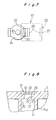
- the construction of the distinguishing member 17 according to the first embodiment may be modified to that as shown in Fig. 8. That is, a large-diameter flange 35, having a diameter larger than that of the shaft 19 which is inserted into the inserting opening 11, is provided in the lower end portion of the shaft 19, and the engaging portion 28 is provided in the upper end of the shaft 19.
- the distinguishing opening 21 is formed on the lower end surface of the flange 35.
- the distinguishing member 17 according to the first and third embodiments may be composed of two parts.
- the state of the tape cartridge may be indicated in the state in which the distinguishing member 17 has been mounted in the inserting opening 11 and the state in which the distinguishing member 17 has been removed from the case 1.
- the mechanism 26 may be composed of parts separate from those of the distinguishing member 17 and the case 1.
- FIGs. 9 through 14 the embodiments of the cassette information detecting mechanism of the magnetic recording/reproducing device according to the present invention is described below.
- the construction of the tape cassette to be mounted on the magnetic recording/reproducing device according to the embodiments described below is the same as that of the tape cassette according to the above-described second embodiment.
- Fig. 9 is a perspective view showing the construction of a cassette information detecting mechanism according to a first embodiment of the present invention.
- a sliding member 50 slides along the peripheral surface 51b of an emission element 51 vertically.
- the sliding member 50 has four through-holes 50a formed on the peripheral surface thereof; an arm 50b projecting radially from the peripheral surface thereof; and at least one sliding groove 50c formed vertically on the peripheral surface thereof.
- Two through-holes 50a are formed at a phase interval of 180° in the same level in the circumferential direction of the sliding member 50.
- the sliding member 50 is tapered in the upper portion thereof so that it can be inserted into the inserting opening 17.
- the cassette information detecting mechanism further comprises a spring 52 for urging the sliding member 50 upward.
- An engaging portion 50d formed at the lower end of the sliding groove 50c engages a convex portion 51c formed on the peripheral surface 51b of the emission section 51. Consequently, the upward movement of the sliding member 50 is prevented and held at a predetermined position.
- Figs. 10 and 11 are sectional views showing the operation of the cassette information detecting mechanism.
- Fig. 10 shows a state in which the inserting opening 11 is closed by the distinguishing member 17 and the sliding member 50 is disposed below the distinguishing member 17.
- the arm 50b presses a terminal 53a of a cassette information detecting sensor 53 downward when the sliding member 50 is placed below the distinguishing member 17.
- the sensor 53 fixed to a base 54 is turned on and beams emitted by the emission section 51a of the emission element 51 pass through the through-hole 50a disposed on an upper portion thereof and the projecting window 16 are introduced toward a light-receiving element as shown by arrows.
- Fig. 11 shows a state in which the distinguishing member 17 is moved away from the lower position and as a result, the inserting opening 11 is opened and the sliding member 50 is placed at the upper position. At this time, the arm 50b of the sliding member 50 disengages from the terminal 53a of the sensor 53. As a result, the sensor 53 is turned off. At this time, beams emitted by the emission section 51a of the emission element 51 pass through the through-hole 50a disposed in the upper portion thereof and the projecting window 16 are introduced toward the light-receiving element as shown by arrows. Since the cassette information detecting mechanism according to the present invention operates as described above, it reliably detects the information of the tape cassette without preventing the detection of the ends of the tape.
- Fig. 12 is a perspective view showing the construction of a cassette information detecting mechanism according to a second embodiment of the present invention.
- the emission element 51 has a through-hole 55 in the center thereof and the emission section 51a at an upper portion thereof.
- the emission element 51 is mounted on the base 54 similarly to the first embodiment.
- An E-ring 56 for fixing the arm 50b to a detecting pin 57 at a predetermined position thereof is fixed to a groove 57a of the detecting pin 57.
- a spring 52 presses a disk 57b formed at the lower end of the detecting pin 57, thus urging the detecting pin 57 upward.
- the emission element 51 comprises a regulating groove 51d for regulating the pivotal motion of the arm 50b and allowing the arm 50b to move only vertically together with the detecting pin 57.
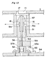
- Fig. 13 shows a state in which the inserting opening 11 is closed by the distinguishing member 17 and the detecting pin 57 is disposed below the distinguishing member 17.
- the arm 50b presses the terminal 53a of the sensor 53, fixed to a predetermined position of the base 54, downward when the detecting pin 57 is disposed below the distinguishing member 17.
- the sensor 53 is turned on. Beams emitted by the emission section 51a of the emission element 51 pass through the projecting window 16 as shown by arrows and are introduced toward the light-receiving element 15 because nothing intercepts them.
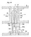
- Fig. 14 shows a state in which the distinguishing member 17 is moved away from the lower position and as a result, the inserting opening 11 is opened and the detecting pin 57 is placed at the upper position. At this time, the arm 50b mounted on the detecting pin 57 disengages from the terminal 53a of the sensor 53. As a result, the sensor 53 is turned off. Similarly to Fig. 13, beams emitted by the emission element 51 pass through the projecting window 16 of the case 1 and are introduced toward the light-receiving element as shown by arrows.
- the configuration of the emission element 51 according to the first embodiment is as simple as that of the conventional one and thus the magnetic recording/reproducing device having a simple construction can be manufactured at a low cost and further is reliable in its operation.
- the first distinguishing member is provided in an upper portion of the inserting opening into which the emission element is inserted. Therefore, the projecting section which is inserted into the inserting opening and the second distinguishing member can be accommodated both in a larger size tape cassette and a smaller size tape cassette.
- the internal construction of the device can be simplified as compared with the construction in which the first distinguishing member is disposed in the rear corner of the case.
- the first distinguishing member can be appropriately disposed in a space formed by utilizing the upper portion of the inserting opening. Therefore, parts can be appropriately mounted in the smaller size tape cassette with the detecting optical path placed at an appropriate position.
- first distinguishing member in addition to the first distinguishing member provided in the inserting opening, another first distinguishing member can be provided in a rear corner of the case.
- a tape cassette having a function of detecting the state of the tape cassette is mounted in the opening for detecting the leading and rear ends of a tape.
- the leading and rear ends of the tape and state of the tape cassette can be reliably detected by a simple construction.
- the device can be made to be compact because the reduced space of the detecting mechanism.
Landscapes
- Automatic Tape Cassette Changers (AREA)
- Packaging Of Annular Or Rod-Shaped Articles, Wearing Apparel, Cassettes, Or The Like (AREA)
Applications Claiming Priority (4)
| Application Number | Priority Date | Filing Date | Title |
|---|---|---|---|
| JP272176/91 | 1991-10-21 | ||
| JP3272176A JP3009271B2 (ja) | 1991-10-21 | 1991-10-21 | 磁気記録再生装置及びこれに用いる磁気テープカセット |
| JP38645/92 | 1992-01-28 | ||
| JP3864592A JPH05205441A (ja) | 1992-01-28 | 1992-01-28 | テープカートリッジ |
Publications (2)
| Publication Number | Publication Date |
|---|---|
| EP0543159A1 true EP0543159A1 (fr) | 1993-05-26 |
| EP0543159B1 EP0543159B1 (fr) | 1996-04-10 |
Family
ID=26377917
Family Applications (1)
| Application Number | Title | Priority Date | Filing Date |
|---|---|---|---|
| EP92117891A Expired - Lifetime EP0543159B1 (fr) | 1991-10-21 | 1992-10-20 | Cassette à bande et dispositif magnétique d'enregistrement/reproduction |
Country Status (3)
| Country | Link |
|---|---|
| US (1) | US5537279A (fr) |
| EP (1) | EP0543159B1 (fr) |
| DE (1) | DE69209780T2 (fr) |
Families Citing this family (3)
| Publication number | Priority date | Publication date | Assignee | Title |
|---|---|---|---|---|
| JPH11185441A (ja) * | 1997-12-24 | 1999-07-09 | Aiwa Co Ltd | データストレージ用カセットおよびデータ用記録再生装置 |
| JP4124384B2 (ja) * | 1998-05-15 | 2008-07-23 | 富士フイルム株式会社 | 磁気テープカートリッジ |
| US6739536B2 (en) | 2002-10-04 | 2004-05-25 | International Business Machines Corporation | Optical detection of alignment and/or absence of tape cartridge leader pin |
Citations (3)
| Publication number | Priority date | Publication date | Assignee | Title |
|---|---|---|---|---|
| US4343024A (en) * | 1980-05-08 | 1982-08-03 | Tsutomu Kawai | Device for detecting tape end of magnetic recording apparatus |
| EP0169546A1 (fr) * | 1984-07-23 | 1986-01-29 | Sony Corporation | Cassette pour bande magnétique |
| DE8813593U1 (de) * | 1988-10-29 | 1990-03-01 | Huwil-Werke GmbH Möbelschloß- und Beschlagfabriken, 5207 Ruppichteroth | Schließvorrichtung als Einlegesperre für Magnetbandkassetten, insbesondere Videobandkassetten |
Family Cites Families (8)
| Publication number | Priority date | Publication date | Assignee | Title |
|---|---|---|---|---|
| JPS58196647A (ja) * | 1982-05-12 | 1983-11-16 | Toshiba Corp | テ−プレコ−ダのリ−ル台装置 |
| JPS59107472A (ja) * | 1982-12-10 | 1984-06-21 | Victor Co Of Japan Ltd | テ−プカセツト |
| US4743984A (en) * | 1985-09-25 | 1988-05-10 | Ampex Corporation | Scheme for encoding a magnetic tape cassette |
| US4791504A (en) * | 1986-09-11 | 1988-12-13 | Sony Corporation | Tape cassette with lid lock and tape characteristic indicating member |
| JP2570349B2 (ja) * | 1987-12-22 | 1997-01-08 | ソニー株式会社 | テープカセット |
| US4993661A (en) * | 1989-05-12 | 1991-02-19 | Minnesota Mining And Manufacturing Company | Tape cassette with tape leader detection improvements |
| US5316234A (en) * | 1991-05-29 | 1994-05-31 | Matsushita Electric Industrial Co., Ltd. | Tape cassette for cassette recording/reproducing apparatus |
| DE4229043A1 (de) * | 1991-09-03 | 1993-03-18 | Funai Electric Co | Bandende-erkennungsvorrichtung fuer tapedecks |
-
1992
- 1992-10-20 DE DE69209780T patent/DE69209780T2/de not_active Expired - Fee Related
- 1992-10-20 EP EP92117891A patent/EP0543159B1/fr not_active Expired - Lifetime
-
1994
- 1994-07-25 US US08/279,895 patent/US5537279A/en not_active Expired - Fee Related
Patent Citations (3)
| Publication number | Priority date | Publication date | Assignee | Title |
|---|---|---|---|---|
| US4343024A (en) * | 1980-05-08 | 1982-08-03 | Tsutomu Kawai | Device for detecting tape end of magnetic recording apparatus |
| EP0169546A1 (fr) * | 1984-07-23 | 1986-01-29 | Sony Corporation | Cassette pour bande magnétique |
| DE8813593U1 (de) * | 1988-10-29 | 1990-03-01 | Huwil-Werke GmbH Möbelschloß- und Beschlagfabriken, 5207 Ruppichteroth | Schließvorrichtung als Einlegesperre für Magnetbandkassetten, insbesondere Videobandkassetten |
Also Published As
| Publication number | Publication date |
|---|---|
| US5537279A (en) | 1996-07-16 |
| DE69209780D1 (de) | 1996-05-15 |
| EP0543159B1 (fr) | 1996-04-10 |
| DE69209780T2 (de) | 1996-09-12 |
Similar Documents
| Publication | Publication Date | Title |
|---|---|---|
| EP0406943A1 (fr) | Système d'enregistrement/reproduction de signaux sur/de bande magnétique, et appareil et cassette à utiliser dans ce système | |
| CA2086312C (fr) | Dispositif debiteur et recepteur de bande magnetique et cassettes de bande magnetique connexes | |
| CA2050138C (fr) | Cassette de bande magnetique | |
| US5537279A (en) | Tape cassette and magnetic recording/reproducing device | |
| US7104488B2 (en) | Gripped part structure of recording tape cartridge | |
| EP0793231B1 (fr) | Cartouche à bande | |
| US5359477A (en) | Recording and/or reproducing apparatus having a cassette loading apparatus | |
| US20020172140A1 (en) | Cartridge housing a recording medium and drive device for recording medium | |
| EP0431898A2 (fr) | Cassettes à bande magnétique | |
| US5495374A (en) | Automatic loader mechanism for magnetic tape cartridge with tension control | |
| US5850316A (en) | Tape cartridge and driving system having rotation detection unit for drive roll to maintain constant contact pressure with the capstan roll | |
| US20030222549A1 (en) | Apparatus where media having different configurations are installed | |
| JP3009271B2 (ja) | 磁気記録再生装置及びこれに用いる磁気テープカセット | |
| US6892974B2 (en) | Recording tape cartridge | |
| US5999363A (en) | Cassette housing having cassette stoppers to prevent mis-insertion | |
| JP3550857B2 (ja) | テープカートリッジ | |
| JPH10208431A (ja) | 磁気ディスクカートリッジ | |
| JP2002093028A (ja) | 磁気ディスク記録再生システム | |
| JP2998544B2 (ja) | テープカセット | |
| JPH0547155A (ja) | デイスクカートリツジ | |
| JPH08329652A (ja) | テープカートリッジ | |
| JPH0714340A (ja) | データカートリッジ | |
| EP0232620A2 (fr) | Cassettes à bande magnétique | |
| JPH08329640A (ja) | テープカートリッジ | |
| JP2002093007A (ja) | 磁気ディスク記録再生システム |
Legal Events
| Date | Code | Title | Description |
|---|---|---|---|
| PUAI | Public reference made under article 153(3) epc to a published international application that has entered the european phase |
Free format text: ORIGINAL CODE: 0009012 |
|
| AK | Designated contracting states |
Kind code of ref document: A1 Designated state(s): DE FR GB |
|
| 17P | Request for examination filed |
Effective date: 19930818 |
|
| 17Q | First examination report despatched |
Effective date: 19931130 |
|
| GRAH | Despatch of communication of intention to grant a patent |
Free format text: ORIGINAL CODE: EPIDOS IGRA |
|
| GRAA | (expected) grant |
Free format text: ORIGINAL CODE: 0009210 |
|
| AK | Designated contracting states |
Kind code of ref document: B1 Designated state(s): DE FR GB |
|
| REF | Corresponds to: |
Ref document number: 69209780 Country of ref document: DE Date of ref document: 19960515 |
|
| ET | Fr: translation filed | ||
| PLBE | No opposition filed within time limit |
Free format text: ORIGINAL CODE: 0009261 |
|
| STAA | Information on the status of an ep patent application or granted ep patent |
Free format text: STATUS: NO OPPOSITION FILED WITHIN TIME LIMIT |
|
| 26N | No opposition filed | ||
| REG | Reference to a national code |
Ref country code: GB Ref legal event code: IF02 |
|
| PGFP | Annual fee paid to national office [announced via postgrant information from national office to epo] |
Ref country code: GB Payment date: 20031011 Year of fee payment: 12 |
|
| PGFP | Annual fee paid to national office [announced via postgrant information from national office to epo] |
Ref country code: FR Payment date: 20031030 Year of fee payment: 12 |
|
| PGFP | Annual fee paid to national office [announced via postgrant information from national office to epo] |
Ref country code: DE Payment date: 20031124 Year of fee payment: 12 |
|
| PG25 | Lapsed in a contracting state [announced via postgrant information from national office to epo] |
Ref country code: GB Free format text: LAPSE BECAUSE OF NON-PAYMENT OF DUE FEES Effective date: 20041020 |
|
| PG25 | Lapsed in a contracting state [announced via postgrant information from national office to epo] |
Ref country code: DE Free format text: LAPSE BECAUSE OF NON-PAYMENT OF DUE FEES Effective date: 20050503 |
|
| GBPC | Gb: european patent ceased through non-payment of renewal fee |
Effective date: 20041020 |
|
| PG25 | Lapsed in a contracting state [announced via postgrant information from national office to epo] |
Ref country code: FR Free format text: LAPSE BECAUSE OF NON-PAYMENT OF DUE FEES Effective date: 20050630 |
|
| REG | Reference to a national code |
Ref country code: FR Ref legal event code: ST |