EP0543332B1 - Verfahren und Vorrichtung zur Einstellung des Weissabgleichs einer Projektions-Farbanzeigevorrichtung - Google Patents
Verfahren und Vorrichtung zur Einstellung des Weissabgleichs einer Projektions-Farbanzeigevorrichtung Download PDFInfo
- Publication number
- EP0543332B1 EP0543332B1 EP92119620A EP92119620A EP0543332B1 EP 0543332 B1 EP0543332 B1 EP 0543332B1 EP 92119620 A EP92119620 A EP 92119620A EP 92119620 A EP92119620 A EP 92119620A EP 0543332 B1 EP0543332 B1 EP 0543332B1
- Authority
- EP
- European Patent Office
- Prior art keywords
- screen
- single color
- cathode ray
- color
- luminance
- Prior art date
- Legal status (The legal status is an assumption and is not a legal conclusion. Google has not performed a legal analysis and makes no representation as to the accuracy of the status listed.)
- Expired - Lifetime
Links
Images


Classifications
-
- H—ELECTRICITY
- H04—ELECTRIC COMMUNICATION TECHNIQUE
- H04N—PICTORIAL COMMUNICATION, e.g. TELEVISION
- H04N9/00—Details of colour television systems
- H04N9/12—Picture reproducers
- H04N9/31—Projection devices for colour picture display, e.g. using electronic spatial light modulators [ESLM]
- H04N9/3179—Video signal processing therefor
- H04N9/3182—Colour adjustment, e.g. white balance, shading or gamut
-
- H—ELECTRICITY
- H04—ELECTRIC COMMUNICATION TECHNIQUE
- H04N—PICTORIAL COMMUNICATION, e.g. TELEVISION
- H04N9/00—Details of colour television systems
- H04N9/12—Picture reproducers
- H04N9/31—Projection devices for colour picture display, e.g. using electronic spatial light modulators [ESLM]
- H04N9/3191—Testing thereof
- H04N9/3194—Testing thereof including sensor feedback
-
- H—ELECTRICITY
- H04—ELECTRIC COMMUNICATION TECHNIQUE
- H04N—PICTORIAL COMMUNICATION, e.g. TELEVISION
- H04N9/00—Details of colour television systems
- H04N9/64—Circuits for processing colour signals
- H04N9/73—Colour balance circuits, e.g. white balance circuits or colour temperature control
Definitions
- the present invention relates to a system and a method for adjusting the white balance of a projector type color display device.
- the white balance adjustment at the manufacturing line has been made by using color sensors. That is, the color sensors are manually attached to the display faces of the three display tubes for sensing the colors displayed on the display faces. All white signals (such as 5IRE signal and 100IRE signal) are fed to each display tube as an external signal, and the white balance adjustment of the color projector is carried out with reference to the information signals issued from the color sensors.
- All white signals such as 5IRE signal and 100IRE signal
- 5IRE signal and 100IRE signal are fed to each display tube as an external signal, and the white balance adjustment of the color projector is carried out with reference to the information signals issued from the color sensors.
- the white balance adjustment at the user side has been made by using a colorimeter and a color-difference meter. That is, the adjustment has been made manually by an inspector who compares, with his or her eyes, the color image on the screen and the reference color data provided by the colorimeter and the color difference meter.
- a white balance control system in which at least a quantity of light of blue out of a standard signal projected on a screen is detected. A ratio of the detected quantity of the light to a whole quantity is calculated. The calculated ratio is compared with a reference ratio, and a deviation of the calculated ratio from the reference ratio is corrected so as to provide a white balance.
- This system needs detector means which are detecting all of the color components red, green and blue and separating means for separating the quantity of light into respective quantities of the three colors to detect the quantities of light and the whole quantity and to calculate the ratio of the detected quantity of the light to the whole quantity.
- a system for adjusting the white balance of a projector type color display device which includes three single color cathode ray tubes from which three single color beams are projected onto a screen to form a colored image on the screen.
- the white balance adjusting system is characterized by a camera for detecting a pedestal luminance value on said screen when said single color cathode ray tubes do not project and for detecting a luminance value of a single color image on said screen; and a control unit for a) previously storing luminance ratios between three single color images on the screen; b) feeding only one of the three cathode ray tubes with the corresponding signal component of an all white signal to cause the same to project said single color image on said screen; c) deriving luminance values of the other two single color images from the detected pedestal luminance value, the detected luminance value of said single color image and said stored luminance ratios; d) controlling said display device in such a manner that said detected luminance value of the other two single color images, respectively, becomes equal to the derived luminance values.
- a method for adjusting the white balance of a projector type color display device which includes three single color cathode ray tubes from which three single color beams are projected onto a screen to form a colored image on the screen.
- the method is characterized by the following steps: (a) detecting a pedestal luminance value on said screen when said single cathode ray tubes do not project; (b) feeding only one of the three cathode ray tubes with the corresponding signal component of an all white signal to cause the same to project a single color image on said screen; (c) detecting a luminance value of said single color image on said screen with a camera; (d) deriving luminance values of the other two single color images from the detected pedestal luminance value, the detected luminance value of said single color image and stored luminance ratios; (e) controlling said display device in such a manner that the detected luminance value of the other two single color images, respectively, becomes equal to the derived luminance values; and (f) repeating the steps (b), (c), (d) and (e) on the other two cathode ray tubes.
- a method for adjusting the white balance of a plurality of projector type color display devices each device including three single color cathode ray tubes from which three single color beams are projected onto a screen to form a colored image on the screen.
- the method is characterized by the following steps: (a) preparing a reference color display device whose white balance has been already adjusted according to Claim 7; (b) feeding only one of the three cathode ray tubes of said reference color display device with the corresponding signal component of an all white signal to cause the same to project a single color image on said screen; (c) detecting a luminance value of said single color image on said screen with a camera; (d) repeating the steps (b) and (c) on the other two cathode ray tubes of said reference color display device thereby to respectively provide reference luminance values of the three cathode ray tubes of the reference color display device; (e) detecting luminance values of three single color images on the screen with a camera, which images are provided by the three cathode ray tubes of one of the plural color display devices to be adjusted; (f) controlling the gain and the bias of the selected color display device in such a manner that the detected luminance values are controlled to the reference luminance values; and (g) repeating the steps of
- FIG. 1 there is shown a block diagram of a system for adjusting the white balance of one color projector, which is made in accordance with the present invention.
- denoted by numeral 1 is the color projector whose white balance is to be adjusted
- 2 is a screen onto which a color image from the projector 1 is projected
- 3 is a black-and-white CCD (charged coupled device) camera which is arranged to face the screen 2.
- CCD charged coupled device
- the control unit 4 is a microcomputer which comprises an A/D (analog/digital) converter section 41, a CPU (central processing unit) section 42, a RAM and ROM section 43 and an I/O (input/output) section 44.
- A/D analog/digital
- CPU central processing unit
- RAM random access memory
- ROM read-only memory
- I/O input/output
- the projector 1 comprises three (viz., Red, Green and Blue) high intensity cathode ray tubes (viz., CRTs) from which respective (viz., Red, Green and blue) brilliant color beams are projected forward onto the screen 2 to form a colored image on the screen 2.
- CRTs cathode ray tubes
- the Green cathode ray tube projects a green color image (that is, the green component of the all white signal of H/L side) on the screen 2.
- the black-and-white CCD camera 3 takes or detects the luminance (or brightness) of the green color image on the screen 2.
- the analog signal from the CCD camera 3 is converted into a digital type by the A/D converter 41 and fed to the CPU 42.
- all white signal of C/O (cut-off) side is fed to the Green cathode ray tube to cause the same to project another green color image (that is, the green component of all white signal of C/O side) on the screen 2.
- the CCD camera 3 detects the luminance value of this green color image on the screen 2 to feed the control unit 4 with an information on the luminance value.
- the CPU 42 of the control unit 4 treats the luminance representing data from the CCD camera 3 with reference to a predetermined reference data stored in the memory section 43 to provide a display means of the commander 5 with an information which is needed for adjusting the Green cathode ray tube of the color projector 1. With reference to the information thus displayed on the commander 5, an operator manipulates gain and bias volumes of the Green cathode ray tube.
- FIG. 2 there is shown a flowchart which depicts the steps for adjusting the white balance of the color projector 1.
- the ROM of the control unit 4 has previously memorized reference luminance ratios between Green, Red and Blue color images on the screen 2 on three reference color temperatures which are, for example, 6500°K, 3200°K and 9300°K.
- the CCD camera 3 has an integration function to deal with a dark picture on the screen 2.
- step S-1 the number of integration in the CCD camera 3 on the H/L side and that on the C/O side are both calculated in accordance with the luminance values of single color (viz.,, green) images on the screen 2, which images have the color temperature of 6500°K.
- the two types of single (viz., green) color images are provided by feeding the Green cathode ray tube with all white signal of the H/L and C/O sides.
- step S-2 the pedestal level of the single color image (viz., the blanking level of the image signal produced when the screen 2 does not prepare any luminous image thereon) is derived.
- step S-3 the luminance value of the single (viz., green) color image on the screen 2 is read on each of the "H/L” and "C/O" sides.
- step S-4 the luminance values of the other two (viz., Red and Blue) color images are derived from the just read luminance value of "Green” in view of the previously memorized luminance ratio between "G", "R” and "B” of the color temperature of 6500°K.
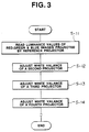
- FIG. 3 there is shown another flowchart which depicts the steps for adjusting the white balance of a plurality of color projectors.
- a reference or first projector 1 is prepared, whose white balance has been already adjusted in the above-mentioned manner.
- the luminance values of the reference colors "R", "G” and “B” of the first projector 1 are detected on both the “H/L” and “C/O” sides. That is, at first, one of the Red, Green and Blue cathode ray tubes is energized and fed with all white signal of H/L and C/O sides. With this, the selected cathode ray tube projects one color image on the screen 2. The luminance value of the color image is detected by the black-and-white CCD camera 3. Similar operation is carried out on the other two cathode ray tubes to detect the luminance values of the other two color images. With these steps, six reference luminance values "RH1", “GH1", “BH1”, “RC1”, “GC1” and “BC1" of the reference projector 1 are provided.
- step S-12 by controlling gain and bias volumes of each cathode ray tube of a second projector 1' which is to be adjusted, the tracking of the "H/L" side and that of the "C/O" side are adjusted in such a manner that the luminance values "RH1-2", “GH1-2”, “BH1-2”, “RC1-2”, “GC1-2” and “BC1-2” of this second projector 1' are the same as the reference luminance values "RH1", “GH1", “BH1”, “RC1", “GC1” and “BC1" of the reference or first projector 1.
- steps S-13 and S-14 similar operation is carried out for adjusting the white balance of third and fourth projectors 1" and 1"'.
- a black-and-white type CCD camera 3 is used.
- a color type CCD camera may be used.
- all of the three cathode ray tubes project their single color images onto the screen 2 at the same time to form all white image on the screen 2, and the color CCD camera detects the luminance values of the Green, Red and Blue color components of the all white image at the same time.
Landscapes
- Engineering & Computer Science (AREA)
- Multimedia (AREA)
- Signal Processing (AREA)
- Processing Of Color Television Signals (AREA)
- Video Image Reproduction Devices For Color Tv Systems (AREA)
- Testing, Inspecting, Measuring Of Stereoscopic Televisions And Televisions (AREA)
Claims (11)
- Vorrichtung zur Einstellung des Weißabgleichs einer Projektions-Farbanzeigevorrichtung (1), die drei einfarbige Kathodenstrahlröhren enthält, von denen drei einfarbige Strahlen auf einen Bildschirm (2) projiziert werden, um auf dem Bildschirm (2) ein Farbbild darzustellen, gekennzeichnet durch
eine Kamera (3) zur Detektion eines Schwarzabhebungsluminanzwerts auf dem Bildschirm (2), wenn die einfarbigen Kathodenstrahlröhren nicht projizieren, und zur Detektion eines Luminanzwerts eines einfarbigen Bildes auf dem Bildschirm; und eine Steuereinheit (4), uma) im Vorhinein Luminanzverhältnisse zwischen drei einfarbigen Bildern auf dem Bildschirm zu speichern;b) nur eine der drei Kathodenstrahlröhren mit dem korrespondierenden Signalanteil eines Weißsignals anzusteuern, damit diese das einfarbige Bild auf den Bildschirm (2) projiziert;c) aus dem detektierten Schwarzabhebungsluminanzwert, dem detektierten Luminanzwert des einfarbigen Bilds und den gespeicherten Luminanzverhältnissen die Luminanzwerte der anderen beiden einfarbigen Bilder abzuleiten;d) die Anzeigevorrichtung (1) so zu steuern, daß der detektierte Luminanzwert der anderen beiden einfarbigen Bilder jeweils gleich zu den abgeleiteten Luminanzwerten ist. - Vorrichtung nach Anspruch 1, dadurch gekennzeichnet, daß die Steuereinheit (4) die ausgewählte Kathodenstrahlröhre mit einem Weißsignal für ein helles Bild und einem Weißsignal für ein dunkles Bild ansteuert.
- Vorrichtung nach Anspruch 2, dadurch gekennzeichnet, daß die Kamera (3) entweder eine Schwarzweiß-CCD-Kamera oder eine Farb-CCD-Kamera ist.
- Vorrichtung nach Anspruch 3, dadurch gekennzeichnet, daß die Steuereinheit (4) ein Computer ist, der ein Referenzluminanzverhältnis zwischen einem grünen, einem roten und einem blauen Farbbild bei einer Referenzfarbtemperatur auf dem Bildschirm vorbereitet, wobei dieses Referenzluminanzverhältnis bei der Ableitung der anderen einfarbigen Bilder verwendet wird.
- Vorrichtung nach Anspruch 2, dadurch gekennzeichnet, daß die CCD-Kamera so angeordnet ist, daß sie dem Bildschirm gegenübersteht.
- Vorrichtung nach Anspruch 1, gekennzeichnet durch eine Anzeigevorrichtung, die eine zur Einstellung der Verstärkung und der Vorspannung der ausgewählten Kathodenstrahlröhre benötigte Information anzeigt.
- Verfahren zur Einstellung des Weißabgleichs einer Projektions-Farbanzeigevorrichtung (1), die drei einfarbige Kathodenstrahlröhren enthält, von denen drei einfarbige Strahlen auf einen Bildschirm (2) projiziert werden, um auf dem Bildschirm (2) ein Farbbild darzustellen, das Verfahren ist gekennzeichnet durch die folgenden Schritte:a) Detektion eines Schwarzabhebungsluminanzwerts auf dem Bildschirm (2), wenn die einzelnen Kathodenstrahlröhren nicht projizieren;b) Ansteuern nur einer der drei Kathodenstrahlröhren mit dem korrespondierenden Signalanteil eines Weißsignals, damit diese ein einfarbiges Bild auf den Bildschirm projiziert;c) Detektion eines Luminanzwerts des einfarbigen Bildes auf dem Bildschirm mit einer Kamera (3);d) Ableiten der Luminanzwerte der anderen beiden einfarbigen Bilder aus dem detektierten Schwarzabhebungsluminanzwert, dem detektierten Luminanzwert des einfarbigen Bilds und gespeicherten Luminanzverhältnissen;d) Steuern der Anzeigevorrichtung (1) so, daß der detektierte Luminanzwert der anderen beiden einfarbigen Bilder jeweils gleich zu den abgeleiteten Luminanzwerten ist; undf) Wiederholen der Schritte (b), (c), (d) und (e) mit den anderen beiden Kathodenstrahlröhren.
- Verfahren nach Anspruch 7, dadurch gekennzeichnet, daß der Schritt (c) mittels einer Schwarzweiß-CCD-Kamera (3) durchgeführt wird.
- Verfahren nach Anspruch 7, dadurch gekennzeichnet, daß die Ableitung der Luminanzwerte der anderen beiden einfarbigen Bilder in Bezug auf ein gespeichertes Luminanzverhältnis zwischen einem grünen, einem roten und einem blauen Farbbild bei einer Referenzfarbtemperatur auf dem Bildschirm durchgeführt wird.
- Verfahren zur Einstellung des Weißabgleichs einer Mehrzahl ProjektionsFarbanzeigevorrichtungen (1), die jeweils drei einfarbige Kathodenstrahlröhren enthalten, von denen drei einfarbige Strahlen auf einen Bildschirm (2) projiziert werden, um auf dem Bildschirm (2) ein Farbbild darzustellen;
das Verfahren ist gekennzeichnet durch die folgenden Schritte:a) Vorbereiten einer Referenz-Projektions-Farbanzeigevorrichtung (1), deren Weißabgleich schon nach Anspruch 7 eingestellt wurde;b) Ansteuern nur einer der drei Kathodenstrahlröhren der Referenz-Projektions-Farbanzeigevorrichtung (1) mit dem korrespondierenden Signalanteil eines Weißsignals, damit diese ein einfarbiges Bild auf den Bildschirm (2) projiziert;c) Detektion eines Luminanzwerts des einfarbigen Bildes auf dem Bildschirm (2) mit einer Kamera (3);d) Wiederholen der Schritte (b) und (c) bei den anderen beiden Kathodenstrahlröhren der Referenz-Projektions-Farbanzeigevorrichtung (1), um dadurch jeweils Referenzluminanzwerte der drei Kathodenstrahlröhren der Referenz-Projektions-Farbanzeigevorrichtung (1) zu erzeugen;e) Detektion von Luminanzwerten von drei einfarbigen Bildern auf dem Bildschirm mit einer Kamera (3), wobei die Bilder von den drei Kathodenstrahlröhren einer Projektions-Farbanzeigevorrichtung aus der Mehrzahl einzustellender Projektions-Farbanzeigevorrichtungen erzeugt werden;f) Steuern der der Verstärkung und der Vorspannung der ausgewählten Projektions-Farbanzeigevorrichtungen so, daß die detektierten Luminanzwerte auf die Referenzluminanzwerten eingestellt werden; undf) Wiederholen der Schritte (e) und (f) bei den verbleibenden Projektions-Farbanzeigevorrichtungen. - Verfahren nach Anspruch 10, dadurch gekennzeichnet, daß die Farbanzeigevorrichtungen aufeinandergesetzt angeordnet sind, um einen Mehrfachbildschirm zu erzeugen.
Applications Claiming Priority (2)
| Application Number | Priority Date | Filing Date | Title |
|---|---|---|---|
| JP03301915A JP3116472B2 (ja) | 1991-11-18 | 1991-11-18 | ホワイト・バランス調整方法 |
| JP301915/91 | 1991-11-18 |
Publications (3)
| Publication Number | Publication Date |
|---|---|
| EP0543332A2 EP0543332A2 (de) | 1993-05-26 |
| EP0543332A3 EP0543332A3 (en) | 1993-08-11 |
| EP0543332B1 true EP0543332B1 (de) | 1998-01-21 |
Family
ID=17902647
Family Applications (1)
| Application Number | Title | Priority Date | Filing Date |
|---|---|---|---|
| EP92119620A Expired - Lifetime EP0543332B1 (de) | 1991-11-18 | 1992-11-17 | Verfahren und Vorrichtung zur Einstellung des Weissabgleichs einer Projektions-Farbanzeigevorrichtung |
Country Status (4)
| Country | Link |
|---|---|
| US (1) | US5287173A (de) |
| EP (1) | EP0543332B1 (de) |
| JP (1) | JP3116472B2 (de) |
| DE (1) | DE69224153T2 (de) |
Cited By (1)
| Publication number | Priority date | Publication date | Assignee | Title |
|---|---|---|---|---|
| CN101655658B (zh) * | 2008-08-20 | 2011-06-15 | 和硕联合科技股份有限公司 | 显示装置及其色差校正补偿方法 |
Families Citing this family (15)
| Publication number | Priority date | Publication date | Assignee | Title |
|---|---|---|---|---|
| JP2899059B2 (ja) * | 1990-04-27 | 1999-06-02 | キヤノン株式会社 | 投写型テレビジョン装置 |
| US5570140A (en) * | 1993-07-08 | 1996-10-29 | Mitsubishi Denki Kabushiki Kaisha | Projection unit for projection type display apparatus |
| JP3735158B2 (ja) * | 1996-06-06 | 2006-01-18 | オリンパス株式会社 | 画像投影システム、画像処理装置 |
| EP0989757B1 (de) * | 1998-04-15 | 2011-12-07 | Mitsubishi Electric Corporation | Multivision system, farbkalibrierungsverfahren und anzeigevorrichtung |
| CN1213426C (zh) | 1999-08-31 | 2005-08-03 | 松下电器产业株式会社 | 盘再生系统 |
| JP3632574B2 (ja) * | 2000-07-31 | 2005-03-23 | セイコーエプソン株式会社 | 環境適応型の画像表示システムおよび情報記憶媒体 |
| EP1185110B1 (de) * | 2000-08-31 | 2010-02-10 | Texas Instruments Incorporated | Automatische Farbabstimmung für verteiltes Projektionssystem |
| JP3719499B2 (ja) * | 2000-09-13 | 2005-11-24 | セイコーエプソン株式会社 | 補正カーブ生成方法、画像処理方法、画像表示装置および記録媒体 |
| JP2002094822A (ja) * | 2000-09-13 | 2002-03-29 | Seiko Epson Corp | 補正カーブ生成方法、画像処理方法、画像表示装置および記録媒体 |
| JP3719411B2 (ja) * | 2001-05-31 | 2005-11-24 | セイコーエプソン株式会社 | 画像表示システム、プロジェクタ、プログラム、情報記憶媒体および画像処理方法 |
| JP3755593B2 (ja) * | 2002-03-26 | 2006-03-15 | セイコーエプソン株式会社 | 投写型画像表示システム、プロジェクタ、プログラム、情報記憶媒体および画像処理方法 |
| JP3719424B2 (ja) * | 2002-05-09 | 2005-11-24 | セイコーエプソン株式会社 | 画像処理システム、プロジェクタ、画像処理方法、プログラムおよび情報記憶媒体 |
| CA2457248C (en) | 2003-02-07 | 2012-07-17 | Closure Medical Corporation | Applicators, dispensers and methods for dispensing and applying adhesive material |
| JP3620537B2 (ja) | 2003-05-02 | 2005-02-16 | セイコーエプソン株式会社 | 画像処理システム、プロジェクタ、プログラム、情報記憶媒体および画像処理方法 |
| TWI336587B (en) * | 2007-06-12 | 2011-01-21 | Etron Technology Inc | Color calibrating method for setting target gamma curves of target display device |
Family Cites Families (9)
| Publication number | Priority date | Publication date | Assignee | Title |
|---|---|---|---|---|
| US3877068A (en) * | 1970-02-21 | 1975-04-08 | Minolta Camera Kk | Method and apparatus for controlling color balance of a color television system |
| US4485394A (en) * | 1982-09-27 | 1984-11-27 | General Electric Company | Automatic convergence and gray scale correction for television _receivers and projection television systems |
| US4599642A (en) * | 1984-03-02 | 1986-07-08 | Rca Corporation | Video signal processor with bias error compensation |
| JPS61161093A (ja) * | 1985-01-09 | 1986-07-21 | Sony Corp | ダイナミツクユニフオミテイ補正装置 |
| US4962418A (en) * | 1987-06-30 | 1990-10-09 | Kabushiki Kaisha Toshiba | Color picture display apparatus |
| JPH03226091A (ja) * | 1990-01-30 | 1991-10-07 | Pioneer Electron Corp | ホワイトバランス調整装置 |
| JP2814648B2 (ja) * | 1990-02-14 | 1998-10-27 | ソニー株式会社 | 映像装置の表示特性測定方法と装置 |
| JPH04251219A (ja) * | 1990-04-09 | 1992-09-07 | Proxima Corp | スタック形ディスプレーパネル及びその製造方法 |
| JPH04367189A (ja) * | 1991-06-13 | 1992-12-18 | Pioneer Electron Corp | ホワイトバランス調整装置 |
-
1991
- 1991-11-18 JP JP03301915A patent/JP3116472B2/ja not_active Expired - Lifetime
-
1992
- 1992-11-17 EP EP92119620A patent/EP0543332B1/de not_active Expired - Lifetime
- 1992-11-17 DE DE69224153T patent/DE69224153T2/de not_active Expired - Fee Related
- 1992-11-18 US US07/978,367 patent/US5287173A/en not_active Expired - Lifetime
Cited By (1)
| Publication number | Priority date | Publication date | Assignee | Title |
|---|---|---|---|---|
| CN101655658B (zh) * | 2008-08-20 | 2011-06-15 | 和硕联合科技股份有限公司 | 显示装置及其色差校正补偿方法 |
Also Published As
| Publication number | Publication date |
|---|---|
| US5287173A (en) | 1994-02-15 |
| JPH05145956A (ja) | 1993-06-11 |
| DE69224153T2 (de) | 1998-08-20 |
| EP0543332A2 (de) | 1993-05-26 |
| EP0543332A3 (en) | 1993-08-11 |
| JP3116472B2 (ja) | 2000-12-11 |
| DE69224153D1 (de) | 1998-02-26 |
Similar Documents
| Publication | Publication Date | Title |
|---|---|---|
| EP0543332B1 (de) | Verfahren und Vorrichtung zur Einstellung des Weissabgleichs einer Projektions-Farbanzeigevorrichtung | |
| US6256062B1 (en) | Color correction apparatus for matching colors in a signal output from a first image apparatus with those from a second image apparatus | |
| US6075563A (en) | Electronic camera capable of adjusting color tone under different light sources | |
| EP0595649B1 (de) | Anzeigevorrichtung für Bildprojektion und Verfahren zum Korrigieren der Farbungleichmässigkeit darin | |
| US5398058A (en) | Color image pickup device having color temperature converting filters | |
| EP1473933B1 (de) | Bildverarbeitungssystem, Projektor, Speichermedium und Bildverarbeitungsverfahren | |
| US6798446B2 (en) | Method and system for custom closed-loop calibration of a digital camera | |
| US7284867B2 (en) | Projector | |
| US6822695B2 (en) | Surrounding light judging method and video compensation control apparatus using the same | |
| JPH02118595A (ja) | カラーディスプレイ制御システムとその作動方法 | |
| US4931856A (en) | Image sensing apparatus | |
| US4608595A (en) | White balance correction for negative-to-positive conversion | |
| US5181103A (en) | White balance adjusting system for a color television system | |
| US5099316A (en) | White balance adjusting device | |
| EP0395201B1 (de) | Komponentenfarbbalken-Ausrichtungstestsignal | |
| US4635101A (en) | Image conversion apparatus for television signals | |
| US6927792B1 (en) | Television camera and white balance correcting method | |
| CA2104443C (en) | Apparatus for receiving and displaying color television signals having different formats | |
| US4740820A (en) | Method of and apparatus for producing hard copy of color picture adaptive to variations in characteristics of fluorescent screen of recorder CRT | |
| EP0440216B1 (de) | Weissabgleich-Steuersystem | |
| US5293224A (en) | White balance control system | |
| US4891691A (en) | Still image color sequential photographic apparatus | |
| JPH0634509B2 (ja) | ホワイトバランス補正回路 | |
| EP0404693B1 (de) | Farbprojektor mit veränderlicher Ablenkfrequenz | |
| KR100293691B1 (ko) | 플라즈마디스플레이패널의화이트밸런스조정장치 |
Legal Events
| Date | Code | Title | Description |
|---|---|---|---|
| PUAI | Public reference made under article 153(3) epc to a published international application that has entered the european phase |
Free format text: ORIGINAL CODE: 0009012 |
|
| AK | Designated contracting states |
Kind code of ref document: A2 Designated state(s): DE FR GB |
|
| PUAL | Search report despatched |
Free format text: ORIGINAL CODE: 0009013 |
|
| AK | Designated contracting states |
Kind code of ref document: A3 Designated state(s): DE FR GB |
|
| 17P | Request for examination filed |
Effective date: 19940112 |
|
| 17Q | First examination report despatched |
Effective date: 19951221 |
|
| GRAG | Despatch of communication of intention to grant |
Free format text: ORIGINAL CODE: EPIDOS AGRA |
|
| GRAG | Despatch of communication of intention to grant |
Free format text: ORIGINAL CODE: EPIDOS AGRA |
|
| GRAH | Despatch of communication of intention to grant a patent |
Free format text: ORIGINAL CODE: EPIDOS IGRA |
|
| GRAH | Despatch of communication of intention to grant a patent |
Free format text: ORIGINAL CODE: EPIDOS IGRA |
|
| GRAA | (expected) grant |
Free format text: ORIGINAL CODE: 0009210 |
|
| AK | Designated contracting states |
Kind code of ref document: B1 Designated state(s): DE FR GB |
|
| REF | Corresponds to: |
Ref document number: 69224153 Country of ref document: DE Date of ref document: 19980226 |
|
| ET | Fr: translation filed | ||
| PLBE | No opposition filed within time limit |
Free format text: ORIGINAL CODE: 0009261 |
|
| STAA | Information on the status of an ep patent application or granted ep patent |
Free format text: STATUS: NO OPPOSITION FILED WITHIN TIME LIMIT |
|
| 26N | No opposition filed | ||
| PGFP | Annual fee paid to national office [announced via postgrant information from national office to epo] |
Ref country code: FR Payment date: 20011113 Year of fee payment: 10 |
|
| PGFP | Annual fee paid to national office [announced via postgrant information from national office to epo] |
Ref country code: GB Payment date: 20011121 Year of fee payment: 10 |
|
| PGFP | Annual fee paid to national office [announced via postgrant information from national office to epo] |
Ref country code: DE Payment date: 20011203 Year of fee payment: 10 |
|
| REG | Reference to a national code |
Ref country code: GB Ref legal event code: IF02 |
|
| PG25 | Lapsed in a contracting state [announced via postgrant information from national office to epo] |
Ref country code: GB Free format text: LAPSE BECAUSE OF NON-PAYMENT OF DUE FEES Effective date: 20021117 |
|
| PG25 | Lapsed in a contracting state [announced via postgrant information from national office to epo] |
Ref country code: DE Free format text: LAPSE BECAUSE OF NON-PAYMENT OF DUE FEES Effective date: 20030603 |
|
| GBPC | Gb: european patent ceased through non-payment of renewal fee | ||
| PG25 | Lapsed in a contracting state [announced via postgrant information from national office to epo] |
Ref country code: FR Free format text: LAPSE BECAUSE OF NON-PAYMENT OF DUE FEES Effective date: 20030731 |
|
| REG | Reference to a national code |
Ref country code: FR Ref legal event code: ST |