EP0543433A1 - Verfahren und Vorrichtung zur Steuerung des Luft-Kraftstoff-Verhältnisses bei Diesel-Verbrennungsmotoren - Google Patents
Verfahren und Vorrichtung zur Steuerung des Luft-Kraftstoff-Verhältnisses bei Diesel-Verbrennungsmotoren Download PDFInfo
- Publication number
- EP0543433A1 EP0543433A1 EP92203245A EP92203245A EP0543433A1 EP 0543433 A1 EP0543433 A1 EP 0543433A1 EP 92203245 A EP92203245 A EP 92203245A EP 92203245 A EP92203245 A EP 92203245A EP 0543433 A1 EP0543433 A1 EP 0543433A1
- Authority
- EP
- European Patent Office
- Prior art keywords
- air
- fuel
- fuel ratio
- sensed
- operating condition
- Prior art date
- Legal status (The legal status is an assumption and is not a legal conclusion. Google has not performed a legal analysis and makes no representation as to the accuracy of the status listed.)
- Granted
Links
Images


Classifications
-
- F—MECHANICAL ENGINEERING; LIGHTING; HEATING; WEAPONS; BLASTING
- F02—COMBUSTION ENGINES; HOT-GAS OR COMBUSTION-PRODUCT ENGINE PLANTS
- F02D—CONTROLLING COMBUSTION ENGINES
- F02D41/00—Electrical control of supply of combustible mixture or its constituents
- F02D41/0025—Controlling engines characterised by use of non-liquid fuels, pluralities of fuels, or non-fuel substances added to the combustible mixtures
- F02D41/0047—Controlling exhaust gas recirculation [EGR]
- F02D41/005—Controlling exhaust gas recirculation [EGR] according to engine operating conditions
- F02D41/0052—Feedback control of engine parameters, e.g. for control of air/fuel ratio or intake air amount
-
- F—MECHANICAL ENGINEERING; LIGHTING; HEATING; WEAPONS; BLASTING
- F02—COMBUSTION ENGINES; HOT-GAS OR COMBUSTION-PRODUCT ENGINE PLANTS
- F02B—INTERNAL-COMBUSTION PISTON ENGINES; COMBUSTION ENGINES IN GENERAL
- F02B3/00—Engines characterised by air compression and subsequent fuel addition
- F02B3/06—Engines characterised by air compression and subsequent fuel addition with compression ignition
-
- F—MECHANICAL ENGINEERING; LIGHTING; HEATING; WEAPONS; BLASTING
- F02—COMBUSTION ENGINES; HOT-GAS OR COMBUSTION-PRODUCT ENGINE PLANTS
- F02M—SUPPLYING COMBUSTION ENGINES IN GENERAL WITH COMBUSTIBLE MIXTURES OR CONSTITUENTS THEREOF
- F02M26/00—Engine-pertinent apparatus for adding exhaust gases to combustion-air, main fuel or fuel-air mixture, e.g. by exhaust gas recirculation [EGR] systems
- F02M26/52—Systems for actuating EGR valves
- F02M26/55—Systems for actuating EGR valves using vacuum actuators
- F02M26/56—Systems for actuating EGR valves using vacuum actuators having pressure modulation valves
- F02M26/57—Systems for actuating EGR valves using vacuum actuators having pressure modulation valves using electronic means, e.g. electromagnetic valves
-
- Y—GENERAL TAGGING OF NEW TECHNOLOGICAL DEVELOPMENTS; GENERAL TAGGING OF CROSS-SECTIONAL TECHNOLOGIES SPANNING OVER SEVERAL SECTIONS OF THE IPC; TECHNICAL SUBJECTS COVERED BY FORMER USPC CROSS-REFERENCE ART COLLECTIONS [XRACs] AND DIGESTS
- Y02—TECHNOLOGIES OR APPLICATIONS FOR MITIGATION OR ADAPTATION AGAINST CLIMATE CHANGE
- Y02T—CLIMATE CHANGE MITIGATION TECHNOLOGIES RELATED TO TRANSPORTATION
- Y02T10/00—Road transport of goods or passengers
- Y02T10/10—Internal combustion engine [ICE] based vehicles
- Y02T10/40—Engine management systems
Definitions
- This invention relates to a method and apparatus for controlling the air/fuel ratio in a diesel engine.
- the smoke and particulate emissions from a diesel engine may be lessened by preventing the air/fuel ratio from becoming too rich.
- this rich limit is imposed by mapping the fuel delivery which is preset prior to delivery of the engine. Thereafter, no active corrections are made for, for example, pump wear, fuel viscosity, dirty air filters, ambient changes, so that the actual air/fuel ratio limit may vary from the intended limit.
- the present invention seeks to provide an improved method and apparatus for controlling the air/fuel ratio in a diesel engine.
- This invention can provide an improved diesel engine EGR/fuel control system. More specifically, this invention can provide for closed loop control of the air/fuel ratio to a desired schedule of engine operation dependent air/fuel ratios by control of the amount of exhaust gases recirculated to the engine. Further, the air/fuel ratio may be closed loop limited to a predetermined schedule of engine operation dependent minimum air/fuel ratios.
- the air/fuel ratio of the combustion mixture in the engine cylinders is sensed (such as by an exhaust oxygen sensor) and the sensed air/fuel ratio is controlled to a predetermined scheduled air/fuel ratio by controlling the amount of exhaust gases recirculated.
- the air/fuel ratio is thereafter closed loop adjusted to a predetermined scheduled minimum air/fuel ratio when the sensed air/fuel ratio is less than the minimum and when the sensed air/fuel ratio is greater than the minimum, while the operator command is at a maximum, thereby to provide precise fuel limiting at a predetermined fuel limit schedule.
- a diesel engine 10 is illustrated.
- a single cylinder of the engine is shown for illustration purposes, it being understood that the engine may have any desired number of cylinders.
- the cylinder illustrated includes a combustion space 12 and piston 14. Air is drawn into the combustion space 12 during engine operation from an intake manifold 16 open to the atmosphere via an air intake conduit 18.
- the air intake 18 includes an air meter 20 for providing a measure of the mass air flow into the engine 10.
- the air intake 18 is unthrottled so that the pressure in the intake manifold 16 is substantially at atmospheric pressure.
- Fuel is fed into the cylinders of the engine by means of a solenoid controlled fuel pump that, on the basis of engine rotation, delivers fuel pulses sequentially to fuel injectors, such as the injector 23, which deliver fuel to the combustion space 12.
- the injection pump 22 is controlled to control the amount of fuel fed at each injection event by an engine control computer 24.
- the fuel quantity is primarily controlled by the computer 24 in response to a fuel request input from the driver of the vehicle. This input is provided by a pedal position sensor 26 that monitors the position of the accelerator pedal 28.
- the exhaust gases resulting from the combustion events in the cylinders of the engine 10 are discharged into an exhaust manifold 30 and thereafter into the atmosphere via an exhaust conduit 32.
- the engine 10 further provides for controlled recirculation of exhaust gases from the exhaust manifold 30 to the intake manifold 16 in order to reduce the amount of nitrogen oxides (NO x ) in the exhaust gases discharged into the atmosphere.
- a conduit 34 is provided for directing exhaust gases from the exhaust manifold 30 to the intake manifold 16.
- the conduit 34 includes a normally closed electromagnetic valve 36 for regulating the amount of exhaust gases recirculated.
- This valve is controlled by the computer 24, such as by means of a pulse-width or duty cycle modulated signal, to control the position of the valve to establish the desired amount of EGR.
- the valve 36 is controlled by the computer 24 so as to achieve a predetermined scheduled air/fuel ratio, as will be described.
- An exhaust gas sensor 38 is positioned in the exhaust manifold to monitor the air/fuel ratio of the mixture of air and fuel from the combustion space of the cylinders.
- the sensor 38 is of the type which provides an output which is a measure of air/fuel ratio over a wide range of ratios including the ratios of interest in operation of the diesel engine 10. This air/fuel ratio signal is fed to the computer 24 to enable closed loop control of air/fuel ratio.
- An engine speed signal RPM is also fed to the computer 24.
- This signal may be provided by a conventional toothed wheel driven by the engine output shaft and by an electromagnetic pickup.
- the resulting signal from the pickup has a frequency which is a measure of engine speed.
- the computer also receives inputs from other sensors as required, such as engine position, coolant temperature, as is common in diesel engine controllers. Similarly, a number of other actuators, not related to this embodiment, such as the engine glow plug heating system, can be controlled by the computer 24.
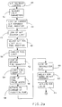
- the engine control computer 24 takes the form of a standard digital computer, with the embodiment described herein being implemented in the form of an operating program stored in the computer's memory. This program is illustrated in Figures 2a and 2b and takes the form of an air/fuel feedback control interrupt routine executed by the computer 24 at interrupt intervals established by a once per cylinder timing signal.
- the air/fuel feedback control routine is entered at step 40 and proceeds to step 42 where the various input parameters used for fuel and EGR control are read and stored in memory.
- These signals include the signal from the air meter 20 providing a measure of the mass air flow, the vehicle operator load command output of the pedal position sensor 26, and the output of the exhaust oxygen sensor providing a measure of the engine air/fuel ratio.
- the operator load command is converted to a percentage of maximum pedal position and is referred to as the fuel request (FR) percent. Further, this step determines and stores in memory engine speed from the engine speed signal RPM.
- the routine next determines the fuel quantity to be injected into each cylinder of the engine.
- the fuel quantity is a predetermined function of FR percent and engine speed, and is closed loop limited at a minimum air/fuel ratio value which is a predetermined function of engine speed.
- an air/fuel ratio feedback fuel modifier AFFM
- AFFM air/fuel ratio feedback fuel modifier
- the AFFM look-up table includes a same number of memory locations, each being associated with a respective one of the operating speed points and having stored therein an AFFM associated with the corresponding operating speed point.
- the AFFM look-up table is addressed by the measured value of engine speed to retrieve the AFFM corresponding to the engine operating speed point defined by the measured speed value.
- a predetermined air/fuel ratio minimum limit is retrieved from a read only memory look-up table storing minimum allowable air/fuel ratio values as a predetermined function of engine speed. These engine calibration values are determined through engine development to provide desired engine performance objectives including, for example, exhaust particulate emissions.
- the air/fuel ratio minimum limit retrieved from memory at the location corresponding to the engine speed stored at step 42 is next adjusted by summing with it the air/fuel ratio feedback modifier retrieved from memory at step 44.
- Step 50 determines the fuel quantity associated with the adjusted air/fuel minimum limit. This is simply the computation of the amount of fuel quantity at the mass air flow stored at step 42 to establish the adjusted air/fuel ratio minimum limit. This computed fuel quantity represents the maximum allowable amount of fuel to be injected.
- Step 52 next determines the desired fuel quantity from a look-up table storing a schedule of fuel quantities as a predetermined function of the FR percent and engine speed. This desired fuel quantity may be adjusted at this step, if desired, as a function of conventional parameters such as engine temperature and engine transients. Step 54 then limits, if required, the determined fuel quantity at the limit established at step 50.
- step 56 The fuel pulse-width required to inject the desired fuel quantity (limited at step 50) is determined at step 56 from a read only memory calibration look-up table of pulse-width values as a predetermined function of fuel quantity and engine speed.
- step 58 provides for actuating the fuel pump on the basis of the determined fuel pulse-width.
- the AFFM value stored at each AFFM memory location referred to in relation to step 44 is updated in response to the air/fuel ratio sensor 38, as will be described, while the engine operates at the corresponding speed operating point as the engine goes through its service life so that the AFFMs stored in the AFFM look-up table provide closed loop air/fuel ratio adjustment of the fuel quantity injected into the engine 10 based on step 58 so as to limit precisely the air/fuel ratio at the desired minimum limit value.
- the routine next provides for controlling the EGR valve to control the amount of exhaust gases recirculated from the exhaust manifold 30 to the intake manifold 16.
- the EGR amount is established on the basis of a desired air/fuel ratio which is a predetermined function of the fuel quantity injected and engine speed and closed loop adjusted based upon the feedback signal from the exhaust oxygen sensor 38.
- the desired air/fuel ratio is determined at step 60 from a look-up table of calibration air/fuel ratios stored in read only memory as a predetermined function of engine speed and fuel quantity determined in the preceding steps. This schedule is determined through engine development to achieve desired operating characteristics such as reduced nitrogen oxides (NO x ) content in the exhaust gases.
- the air/fuel ratio retrieved from memory at the memory location corresponding to the engine speed and fuel quantity may be modified, if necessary, for basic engine operating conditions such as coolant temperature or transient conditions.
- the EGR air/fuel ratio is then modified at step 62 by summing the EGR air/fuel ratio with an air/fuel ratio feedback EGR modifier (AFEM) retrieved from a three-dimensional AFEM look-up table storing such modifiers as a function of fuel quantity and engine speed.
- AFEM air/fuel ratio feedback EGR modifier
- the engine operating range defined by fuel amount and engine speed is divided into a predetermined number of individual operating regions hereafter referred to as operating points.
- the AFEM look-up table includes a same number of memory locations each being associated with a respective one of the operating points and having stored therein an AFEM associated with the corresponding operating point.
- the AFEM look-up table is addressed by the fuel quantity established at steps 52 and 54 and the measured value of engine speed to retrieve the AFEM corresponding to the engine operating point defined by the established fuel quantity and engine speed values.
- the AFEM value stored at each AFEM memory location is updated in response to the air/fuel ratio sensor 38, as will be described, while the engine operates at the corresponding operating point as the engine goes through its service life, so that the AFEM's stored in the AFEM look-up table provide closed loop air/fuel ratio adjustment of the EGR amount so as to control precisely the air/fuel ratio at the desired value.
- the modifiers are corrected, as will be described, on a continual basis in response to the feedback of the air/fuel ratio by the sensor 38 so that the desired air/fuel ratio is precisely obtained.
- step 64 the air/fuel ratio represented by the measured mass air flow and the fuel quantity injected via steps 44 to 58 is determined and compared to the modified air/fuel ratio determined by step 62 and the duty cycle of the signal to the EGR valve 36 is adjusted in a direction to restore the determined air/fuel ratio at the modified air/fuel ratio.
- the modifiers used at step 62 in response to the actual air/fuel ratio sensed by the sensor 38, the resulting actual air/fuel ratio in the combustion chambers will be established at the predetermined desired air/fuel ratio.
- the routine next functions to update the AFFM and AFEM modifiers in response to the exhaust oxygen sensor 38 output to provide closed loop control of the air/fuel ratio at the scheduled air/fuel ratios.
- the AFEM values are updated if EGR is on and the AFFM values are updated if EGR is off.
- the EGR on/off condition is sensed at step 66 and may be based on the state of the EGR control signal established via steps 60 to 64. If the duty cycle of the signal applied to the EGR valve is greater than zero, EGR is considered on and the EGR air/fuel ratio modifiers AFEM are adjusted.
- the program determines at step 68 if the engine has been operating at the same operating point for a predetermined period of time which accounts for any system time lag and ensures that the engine is in a stable operating condition. The AFEM's are updated only when this condition is met. If not met, the program exits the routine at step 69.
- the actual measured air/fuel ratio indicated by the output of the exhaust oxygen sensor 38 is determined at step 70 and then compared with a desired air/fuel ratio.
- the desired air/fuel ratio may be obtained from the same look-up table of calibration air/fuel ratios used at step 60 for EGR control or may be obtained from a separate look-up table establishing a corresponding schedule but having fewer memory locations.
- the engine operating range represented by fuel amount and engine speed is divided into fewer operating regions, or points, each corresponding to one of the look-up table memory locations. In either case, the desired air/fuel ratio is retrieved from memory at the location addressed by the fuel quantity and measured engine speed.
- step 76 first addresses the AFEM look-up table by the last determined values of fuel quantity and engine speed to retrieve the current value of the AFEM for the engine operating point corresponding to those values and then decreases that modifier to effect a decrease in the EGR amount via step 62. If the next step 78 determines that the adjusted modifier is within calibration limits, the adjusted modifier is stored at step 80 in the AFEM look-up table at the same memory location at which the original value was retrieved.
- step 82 addresses the AFEM look-up table by the last determined values of fuel quantity and engine speed to retrieve the current value of the AFEM for the engine operating point corresponding to those values and then increases that modifier to effect an increase in the EGR amount via step 62. If step 78 indicates that the adjusted value is within limits, the adjusted AFEM is stored at the same memory location at which the original value was retrieved.
- step 84 the program determines if the engine is in a stable operating condition, in the same manner as described with reference to step 68. If not, the program exits at step 69. If a stable operating condition is found, the actual air/fuel ratio represented by the output of the exhaust oxygen sensor 38 is determined at step 86 and then compared to the desired air/fuel ratio at step 88.
- the desired air/fuel ratio may be obtained from the same look-up table of calibration air/fuel ratio minimum limits used at step 46 for fuel control or may be obtained from a separate look-up table establishing a corresponding schedule but having fewer memory locations. In this case, the engine operating speed range is divided into fewer operating regions, or points, each corresponding to one of the look-up table memory locations. In either case, the desired air/fuel ratio is retrieved from memory at the location addressed by measured engine speed.
- Step 90 determines if the comparison of step 88 indicates a rich or lean combustion condition relative to the desired air/fuel ratio. If rich, step 92 first addresses the AFFM look-up table by the last measured value of engine speed to retrieve the current value of the AFFM for the engine operating point corresponding to that speed and then decreases that modifier to effect a decrease in the fuel amount when the limit is applied at step 54. If the next step 94 determines that the modifier is within calibration limits, the adjusted modifier is stored at step 96 in the AFFM look-up table at the same memory location from which the original AFFM was retrieved. Otherwise, the step 96 is bypassed and the routine exits at step 69.
- step 90 if the comparison of step 88 indicates a lean air/fuel ratio relative to the desired air/fuel ratio, the AFFM is updated to increase fuel only if the operator is commanding full load represented, for example, by the fuel request percent being at a high value such as 95%. This condition is determined at step 98. If full load is being commanded, a step 100 first addresses the AFFM look-up table by the last measured value of engine speed to retrieve the current value of the AFFM for the engine operating point defined by that speed and then increases that modifier to effect an increase in the fuel quantity when the limit is applied at step 54. If step 94 indicates that the adjusted modifier is within limits, it is stored at the same look-up table address from which the original value was obtained, otherwise step 96 is bypassed.
- the AFFM's are continuously updated in a direction to restore the air/fuel ratio at the desired minimum limit.
Landscapes
- Engineering & Computer Science (AREA)
- Chemical & Material Sciences (AREA)
- Combustion & Propulsion (AREA)
- Mechanical Engineering (AREA)
- General Engineering & Computer Science (AREA)
- Electrical Control Of Air Or Fuel Supplied To Internal-Combustion Engine (AREA)
- Output Control And Ontrol Of Special Type Engine (AREA)
- Exhaust-Gas Circulating Devices (AREA)
Applications Claiming Priority (2)
| Application Number | Priority Date | Filing Date | Title |
|---|---|---|---|
| US07/796,140 US5150694A (en) | 1991-11-22 | 1991-11-22 | Diesel engine closed loop air/fuel ratio control |
| US796140 | 1991-11-22 |
Publications (2)
| Publication Number | Publication Date |
|---|---|
| EP0543433A1 true EP0543433A1 (de) | 1993-05-26 |
| EP0543433B1 EP0543433B1 (de) | 1996-01-03 |
Family
ID=25167400
Family Applications (1)
| Application Number | Title | Priority Date | Filing Date |
|---|---|---|---|
| EP92203245A Expired - Lifetime EP0543433B1 (de) | 1991-11-22 | 1992-10-21 | Verfahren und Vorrichtung zur Steuerung des Luft-Kraftstoff-Verhältnisses bei Diesel-Verbrennungsmotoren |
Country Status (4)
| Country | Link |
|---|---|
| US (1) | US5150694A (de) |
| EP (1) | EP0543433B1 (de) |
| JP (1) | JP2647317B2 (de) |
| DE (1) | DE69207359T2 (de) |
Cited By (3)
| Publication number | Priority date | Publication date | Assignee | Title |
|---|---|---|---|---|
| EP0907016A3 (de) * | 1997-09-16 | 2000-11-29 | Toyota Jidosha Kabushiki Kaisha | Selbstzündende Brennkraftmaschine |
| EP0964140A3 (de) * | 1998-03-17 | 2001-03-28 | Toyota Jidosha Kabushiki Kaisha | Motor mit Verdichtungszündung |
| FR2830772A1 (fr) * | 2001-10-12 | 2003-04-18 | Volkswagen Ag | Procedes et dispositif de desulfuration d'un catalyseur a accumulation de nox, implante en aval d'un moteur diesel |
Families Citing this family (23)
| Publication number | Priority date | Publication date | Assignee | Title |
|---|---|---|---|---|
| DE4239773C2 (de) * | 1992-11-26 | 1999-04-22 | Audi Ag | Verfahren und Vorrichtung zur Steuerung der rückgeführten Abgasmenge bei einer Brennkraftmaschine |
| JP3070334B2 (ja) * | 1993-04-16 | 2000-07-31 | トヨタ自動車株式会社 | ディーゼル機関の燃料噴射制御装置 |
| US5377651A (en) * | 1993-12-27 | 1995-01-03 | General Motors Corporation | Closed-loop control of a diesel engine |
| JP3603398B2 (ja) * | 1995-08-01 | 2004-12-22 | 日産自動車株式会社 | 内燃機関の制御装置 |
| DE19615545C1 (de) * | 1996-04-19 | 1997-06-12 | Daimler Benz Ag | Einrichtung zur Dieselmotorbetriebsregelung mit Abgasrückführung und Ansaugluftdrosselung |
| EP0803645B1 (de) * | 1996-04-23 | 2004-02-04 | Toyota Jidosha Kabushiki Kaisha | Selbstzündende Brennkraftmaschine |
| US5901683A (en) * | 1997-07-28 | 1999-05-11 | General Electric Company | Indirect monitoring and control of visible exhaust emissions from a diesel engine |
| US6354268B1 (en) | 1997-12-16 | 2002-03-12 | Servojet Products International | Cylinder pressure based optimization control for compression ignition engines |
| US6273076B1 (en) | 1997-12-16 | 2001-08-14 | Servojet Products International | Optimized lambda and compression temperature control for compression ignition engines |
| US6079395A (en) * | 1998-09-30 | 2000-06-27 | Caterpillar Inc. | Exhaust gas recirculation system |
| US6370935B1 (en) | 1998-10-16 | 2002-04-16 | Cummins, Inc. | On-line self-calibration of mass airflow sensors in reciprocating engines |
| JP3681041B2 (ja) * | 1999-02-16 | 2005-08-10 | 三菱電機株式会社 | 筒内噴射式内燃機関の制御装置 |
| US6508241B2 (en) | 2001-01-31 | 2003-01-21 | Cummins, Inc. | Equivalence ratio-based system for controlling transient fueling in an internal combustion engine |
| JP3804480B2 (ja) * | 2001-07-13 | 2006-08-02 | マツダ株式会社 | ディーゼルエンジンの制御装置及び制御方法 |
| FR2851014B1 (fr) | 2003-02-07 | 2008-03-14 | Renault Sa | Procede d'estimation du rapport air/carburant d'un moteur, procede de controle d'un moteur utilisant celui-ci et dispositif correspondant |
| US6899093B2 (en) * | 2003-09-17 | 2005-05-31 | General Motors Corporation | Control system for NOx control for cam phaser and/or EGR systems |
| US20060162689A1 (en) * | 2005-01-25 | 2006-07-27 | Visteon Global Technologies, Inc. | Method of controlling diesel engine combustion process in a closed loop using ionization feedback |
| US7469177B2 (en) * | 2005-06-17 | 2008-12-23 | Honeywell International Inc. | Distributed control architecture for powertrains |
| FR2958334B1 (fr) * | 2010-03-31 | 2013-11-08 | Valeo Sys Controle Moteur Sas | Procede d'alimentation d'un moteur a essence en regime de suralimentation et dispositif associe |
| WO2011133153A1 (en) * | 2010-04-22 | 2011-10-27 | International Engine Intellectual Property Company, Llc | Engine emission control strategy for smoke and nox |
| FR2959463B1 (fr) | 2010-04-30 | 2013-01-18 | Valeo Sys Controle Moteur Sas | Dispositif d'alimentation en courant electrique d'un groupe moto ventilateur de vehicule automobile. |
| US9840972B2 (en) | 2011-05-25 | 2017-12-12 | Eaton Corporation | Supercharger-based twin charging system for an engine |
| DE102015007393B4 (de) * | 2015-10-23 | 2019-07-11 | Neander Motors Ag | Abgasrückführungssystem für eine Brennkraftmaschine |
Citations (5)
| Publication number | Priority date | Publication date | Assignee | Title |
|---|---|---|---|---|
| US4373497A (en) * | 1981-09-21 | 1983-02-15 | General Motors Corporation | Exhaust gas recirculation control |
| GB2128251A (en) * | 1982-10-14 | 1984-04-26 | Lucas Ind Plc | I.C. engine exhaust gas recirculation system |
| US4541398A (en) * | 1983-06-30 | 1985-09-17 | Honda Giken Kogyo Kabushiki Kaisha | Method of controlling an exhaust gas recirculating valve in an internal combustion engine |
| US4598684A (en) * | 1984-06-22 | 1986-07-08 | Nippondenso Co., Ltd. | Apparatus for controlling air/fuel ratio for internal combustion engine |
| US4644926A (en) * | 1984-03-17 | 1987-02-24 | Mazda Motor Corporation | Diesel cycle engines having heat insulated auxiliary combustion chambers |
Family Cites Families (10)
| Publication number | Priority date | Publication date | Assignee | Title |
|---|---|---|---|---|
| JPS5213583B2 (de) * | 1973-07-26 | 1977-04-15 | ||
| DE3032381C2 (de) * | 1980-08-28 | 1986-07-24 | Robert Bosch Gmbh, 7000 Stuttgart | Elektronische Steuereinrichtung für eine Brennkraftmaschine mit Selbstzündung |
| JPS5749052A (en) * | 1980-09-06 | 1982-03-20 | Mazda Motor Corp | Purifying device of exhaust gas in fuel injection type engine |
| US4411242A (en) * | 1981-04-03 | 1983-10-25 | Nippon Soken, Inc. | Method and apparatus for controlling EGR in internal combustion engine |
| DE3128239C2 (de) * | 1981-07-17 | 1984-10-18 | Pierburg Gmbh & Co Kg, 4040 Neuss | Verfahren und Einrichtung zum Steuern von Abgas-Rückführmengen |
| JPS5963356A (ja) * | 1982-10-01 | 1984-04-11 | Mazda Motor Corp | エンジンの排気ガス還流装置 |
| JPS59192838A (ja) * | 1983-04-14 | 1984-11-01 | Nippon Denso Co Ltd | 空燃比制御方法 |
| JPS59194069A (ja) * | 1983-04-19 | 1984-11-02 | Honda Motor Co Ltd | 排気還流制御装置搭載内燃エンジンの吸気2次空気供給装置 |
| JPS6166854A (ja) * | 1984-09-11 | 1986-04-05 | Toyota Motor Corp | デイ−ゼルエンジンのegr制御装置 |
| JPH0261347A (ja) * | 1988-08-23 | 1990-03-01 | Nissan Motor Co Ltd | ディーゼルエンジンの燃料噴射制御装置 |
-
1991
- 1991-11-22 US US07/796,140 patent/US5150694A/en not_active Expired - Lifetime
-
1992
- 1992-10-21 EP EP92203245A patent/EP0543433B1/de not_active Expired - Lifetime
- 1992-10-21 DE DE69207359T patent/DE69207359T2/de not_active Expired - Lifetime
- 1992-11-24 JP JP4313348A patent/JP2647317B2/ja not_active Expired - Lifetime
Patent Citations (5)
| Publication number | Priority date | Publication date | Assignee | Title |
|---|---|---|---|---|
| US4373497A (en) * | 1981-09-21 | 1983-02-15 | General Motors Corporation | Exhaust gas recirculation control |
| GB2128251A (en) * | 1982-10-14 | 1984-04-26 | Lucas Ind Plc | I.C. engine exhaust gas recirculation system |
| US4541398A (en) * | 1983-06-30 | 1985-09-17 | Honda Giken Kogyo Kabushiki Kaisha | Method of controlling an exhaust gas recirculating valve in an internal combustion engine |
| US4644926A (en) * | 1984-03-17 | 1987-02-24 | Mazda Motor Corporation | Diesel cycle engines having heat insulated auxiliary combustion chambers |
| US4598684A (en) * | 1984-06-22 | 1986-07-08 | Nippondenso Co., Ltd. | Apparatus for controlling air/fuel ratio for internal combustion engine |
Non-Patent Citations (2)
| Title |
|---|
| PATENT ABSTRACTS OF JAPAN vol. 012, no. 445 (M-767)22 November 1988 & JP-A-63 176 647 ( NIPPON DENSO CO LTD ) 20 July 1988 * |
| PATENT ABSTRACTS OF JAPAN vol. 014, no. 235 (M-0975)18 May 1990 & JP-A-20 61 347 ( NISSAN MOTOR CO LTD ) 1 March 1990 * |
Cited By (3)
| Publication number | Priority date | Publication date | Assignee | Title |
|---|---|---|---|---|
| EP0907016A3 (de) * | 1997-09-16 | 2000-11-29 | Toyota Jidosha Kabushiki Kaisha | Selbstzündende Brennkraftmaschine |
| EP0964140A3 (de) * | 1998-03-17 | 2001-03-28 | Toyota Jidosha Kabushiki Kaisha | Motor mit Verdichtungszündung |
| FR2830772A1 (fr) * | 2001-10-12 | 2003-04-18 | Volkswagen Ag | Procedes et dispositif de desulfuration d'un catalyseur a accumulation de nox, implante en aval d'un moteur diesel |
Also Published As
| Publication number | Publication date |
|---|---|
| JP2647317B2 (ja) | 1997-08-27 |
| US5150694A (en) | 1992-09-29 |
| DE69207359T2 (de) | 1996-05-15 |
| JPH05215016A (ja) | 1993-08-24 |
| EP0543433B1 (de) | 1996-01-03 |
| DE69207359D1 (de) | 1996-02-15 |
Similar Documents
| Publication | Publication Date | Title |
|---|---|---|
| EP0543433B1 (de) | Verfahren und Vorrichtung zur Steuerung des Luft-Kraftstoff-Verhältnisses bei Diesel-Verbrennungsmotoren | |
| JP3403728B2 (ja) | 空燃比制御方法 | |
| US4967714A (en) | Apparatus for controlling engine operable on gasoline/alcohol fuel blend | |
| US7150264B2 (en) | Control device for internal combustion engine | |
| US6308671B1 (en) | Method of increasing torque and/or reducing emissions by varying the timing of intake and/or exhaust valves | |
| US5278762A (en) | Engine control apparatus using exhaust gas temperature to control fuel mixture and spark timing | |
| US6112729A (en) | Device for controlling exhaust gas recirculation in an internal combustion engine | |
| US6688283B2 (en) | Engine start strategy | |
| JP3493039B2 (ja) | 内燃機関の制御システム | |
| US5954039A (en) | Air/fuel ratio control system | |
| WO1999035374A1 (en) | System and method for controlling camshaft timing, air/fuel ratio and throttle position in an automotive internal combustion engine | |
| US5988141A (en) | Engine torque control apparatus | |
| EP0659994A2 (de) | Steuerungssystem mit geschlossenem Regelkreis einer Dieselbrennkraftmaschine | |
| US6142117A (en) | Combustion changeover control for engine | |
| US6176227B1 (en) | Control system for cylinder injection type internal combustion engine with exhaust gas recirculation feedback control | |
| EP1132602A2 (de) | Momentensteuerungsschema für ein mager betriebenes Fahrzeug mit niedriger Schadstoffemission | |
| EP0802313B1 (de) | Integrierte Verdünnungssteuerung für eine Brennkraftmaschine | |
| EP1367247B1 (de) | Verfahren zum Kontrollieren einer Brennkraftmaschine | |
| JP3119856B2 (ja) | デイーゼル内燃機関用制御装置 | |
| US6805091B2 (en) | Method for determining the fuel content of the regeneration gas in an internal combustion engine comprising direct fuel-injection with shift operation | |
| US4706632A (en) | Fuel control apparatus for internal combustion engine | |
| US20080312805A1 (en) | Controller and control system for internal combustion engine | |
| US6446596B1 (en) | Method of operating an internal combustion engine | |
| JPH0763124A (ja) | 内燃機関の制御方法および制御装置 | |
| US5462038A (en) | Air/fuel phase control |
Legal Events
| Date | Code | Title | Description |
|---|---|---|---|
| PUAI | Public reference made under article 153(3) epc to a published international application that has entered the european phase |
Free format text: ORIGINAL CODE: 0009012 |
|
| 17P | Request for examination filed |
Effective date: 19930331 |
|
| AK | Designated contracting states |
Kind code of ref document: A1 Designated state(s): DE GB IT |
|
| 17Q | First examination report despatched |
Effective date: 19940304 |
|
| ITF | It: translation for a ep patent filed | ||
| GRAA | (expected) grant |
Free format text: ORIGINAL CODE: 0009210 |
|
| AK | Designated contracting states |
Kind code of ref document: B1 Designated state(s): DE GB IT |
|
| REF | Corresponds to: |
Ref document number: 69207359 Country of ref document: DE Date of ref document: 19960215 |
|
| PLBI | Opposition filed |
Free format text: ORIGINAL CODE: 0009260 |
|
| PLBF | Reply of patent proprietor to notice(s) of opposition |
Free format text: ORIGINAL CODE: EPIDOS OBSO |
|
| 26 | Opposition filed |
Opponent name: ROBERT BOSCH GMBH Effective date: 19961001 |
|
| PLBF | Reply of patent proprietor to notice(s) of opposition |
Free format text: ORIGINAL CODE: EPIDOS OBSO |
|
| PLBO | Opposition rejected |
Free format text: ORIGINAL CODE: EPIDOS REJO |
|
| PLBN | Opposition rejected |
Free format text: ORIGINAL CODE: 0009273 |
|
| 27O | Opposition rejected |
Effective date: 19971210 |
|
| REG | Reference to a national code |
Ref country code: GB Ref legal event code: IF02 |
|
| PGFP | Annual fee paid to national office [announced via postgrant information from national office to epo] |
Ref country code: GB Payment date: 20031015 Year of fee payment: 12 |
|
| PG25 | Lapsed in a contracting state [announced via postgrant information from national office to epo] |
Ref country code: GB Free format text: LAPSE BECAUSE OF NON-PAYMENT OF DUE FEES Effective date: 20041021 |
|
| GBPC | Gb: european patent ceased through non-payment of renewal fee |
Effective date: 20041021 |
|
| PG25 | Lapsed in a contracting state [announced via postgrant information from national office to epo] |
Ref country code: IT Free format text: LAPSE BECAUSE OF NON-PAYMENT OF DUE FEES;WARNING: LAPSES OF ITALIAN PATENTS WITH EFFECTIVE DATE BEFORE 2007 MAY HAVE OCCURRED AT ANY TIME BEFORE 2007. THE CORRECT EFFECTIVE DATE MAY BE DIFFERENT FROM THE ONE RECORDED. Effective date: 20051021 |
|
| PGFP | Annual fee paid to national office [announced via postgrant information from national office to epo] |
Ref country code: DE Payment date: 20101013 Year of fee payment: 19 |
|
| REG | Reference to a national code |
Ref country code: DE Ref legal event code: R071 Ref document number: 69207359 Country of ref document: DE |
|
| REG | Reference to a national code |
Ref country code: DE Ref legal event code: R071 Ref document number: 69207359 Country of ref document: DE |