EP0543479A1 - Walzwerk - Google Patents
Walzwerk Download PDFInfo
- Publication number
- EP0543479A1 EP0543479A1 EP92305939A EP92305939A EP0543479A1 EP 0543479 A1 EP0543479 A1 EP 0543479A1 EP 92305939 A EP92305939 A EP 92305939A EP 92305939 A EP92305939 A EP 92305939A EP 0543479 A1 EP0543479 A1 EP 0543479A1
- Authority
- EP
- European Patent Office
- Prior art keywords
- roll
- shafts
- pair
- stands
- pairs
- Prior art date
- Legal status (The legal status is an assumption and is not a legal conclusion. Google has not performed a legal analysis and makes no representation as to the accuracy of the status listed.)
- Granted
Links
Images

Classifications
-
- B—PERFORMING OPERATIONS; TRANSPORTING
- B21—MECHANICAL METAL-WORKING WITHOUT ESSENTIALLY REMOVING MATERIAL; PUNCHING METAL
- B21B—ROLLING OF METAL
- B21B35/00—Drives for metal-rolling mills, e.g. hydraulic drives
- B21B35/02—Drives for metal-rolling mills, e.g. hydraulic drives for continuously-operating mills
-
- B—PERFORMING OPERATIONS; TRANSPORTING
- B21—MECHANICAL METAL-WORKING WITHOUT ESSENTIALLY REMOVING MATERIAL; PUNCHING METAL
- B21B—ROLLING OF METAL
- B21B1/00—Metal-rolling methods or mills for making semi-finished products of solid or profiled cross-section; Sequence of operations in milling trains; Layout of rolling-mill plant, e.g. grouping of stands; Succession of passes or of sectional pass alternations
- B21B1/16—Metal-rolling methods or mills for making semi-finished products of solid or profiled cross-section; Sequence of operations in milling trains; Layout of rolling-mill plant, e.g. grouping of stands; Succession of passes or of sectional pass alternations for rolling wire rods, bars, merchant bars, rounds wire or material of like small cross-section
- B21B1/18—Metal-rolling methods or mills for making semi-finished products of solid or profiled cross-section; Sequence of operations in milling trains; Layout of rolling-mill plant, e.g. grouping of stands; Succession of passes or of sectional pass alternations for rolling wire rods, bars, merchant bars, rounds wire or material of like small cross-section in a continuous process
-
- B—PERFORMING OPERATIONS; TRANSPORTING
- B21—MECHANICAL METAL-WORKING WITHOUT ESSENTIALLY REMOVING MATERIAL; PUNCHING METAL
- B21B—ROLLING OF METAL
- B21B13/00—Metal-rolling stands, i.e. an assembly composed of a stand frame, rolls, and accessories
- B21B13/005—Cantilevered roll stands
-
- B—PERFORMING OPERATIONS; TRANSPORTING
- B21—MECHANICAL METAL-WORKING WITHOUT ESSENTIALLY REMOVING MATERIAL; PUNCHING METAL
- B21B—ROLLING OF METAL
- B21B35/00—Drives for metal-rolling mills, e.g. hydraulic drives
- B21B35/12—Toothed-wheel gearings specially adapted for metal-rolling mills; Housings or mountings therefor
Definitions
- This invention relates generally to rolling mills, and is concerned in particular with an improvement in single strand block type finishing mills of the type employed in the twist-free rolling of rods, bars and other like products.
- the output shaft 10 of a mill drive motor 12 drives the center gear 14 of a speed increaser 16.
- Gear 14 in turn drives a pair of side gears 18, 20 carried on line shafts 22,24 extending in parallel relationship to the mill pass line P.
- Segments of the line shafts extend through and are journalled for rotation in the roll stands, with their adjacent protruding ends being externally coupled to each other by couplings 26. Because of the staggered relationship of the roll stands, roll stand ST9 is spaced from the speed increaser 16 by a gap which is bridged by a Cardan shaft segment 24a.
- each line shaft segment located within a roll stand carries a drive bevel gear 28 which meshes with a driven bevel gear 30 carried on one of two parallel intermediate drive shafts 32.
- the intermediate drive shafts carry intermeshed spur gears 34.
- the work rolls R are removably mounted in cantilever fashion on the ends of parallel roll shafts 36.
- Each roll shaft carries a pinion gear 38 which meshes with one of the spur gears 34.
- the spur and pinion gears 34, 38 are thus arranged in what is commonly referred to as a "four gear cluster".
- adjustment means are internally provided at each roll stand for adjusting the parting between the work rolls.
- Such adjustment means typically shift the roll shafts 36 and their pinion gears 38 symmetrically in opposite directions in relation to the mill pass line, while allowing the intermediate drive shafts 32 and their intermeshed spur gears 34 to remain undisturbed.
- Guides are provided between the successive work roll pairs to guide the product along the mill pass line.
- the spacing "C” between successive work roll pairs (commonly referred to as the "stand center” distance) will be on the order of 600-800 mm.
- a 16-24 mm. round will be delivered to stand ST1 from an upstream intermediate mill (not shown) at a speed of about 8-18 m/sec., and will exit from the last stand ST10 as a finished 5.5 mm. round at a speed of around 100 m./sec.
- the ratios of the successive bevel gear sets 28,30 and four gear clusters 34,38 are selected to accommodate the rapidly accelerating product and to insure that the product is under a slight tension as it progresses through the mill.
- the cross section of the product exiting from the finishing block will be within tolerances which are acceptable for some but not all purposes.
- a properly rolled 5.5 mm round will have a tolerance at or slightly below the limit of ⁇ 0.15 as specified by ASTM-A29.
- Such products may be used "as is” for many applications, including for example welding mesh, chicken wire, etc.
- tolerance rounds Such products are commonly referred to as "precision rounds”. In the past, this level of precision has been achieved either by subjecting the bars to a separate machining operation after the rolling operation has been completed, or by continuously rolling the bars through additional separately driven "sizing stands".
- the basic objective of the present invention is to enable precision rounds to be rolled in the finishing block, thereby eliminating any need for subsequent separate machining operations or additional rolling in separately driven downstream sizing stands.
- a further objective of the present invention is to roll precision rounds without encouraging unacceptable levels of grain growth.
- Companion objectives include an overall improvement in the tolerances of products finished out of the last stand of the block, as well as the rolling of smaller diameter rounds in the finishing block.
- the modified roll stand includes the conventional intermediate drive shafts carrying intermeshed spur gears, with one of the intermediate drive shafts being mechanically coupled to a respective one of the line shafts by a bevel gear set.
- the intermediate drive shafts are located between and mechanically coupled to two pairs of roll shafts.
- Each pair of roll shafts carries pinion gears meshing with the spur gears on the intermediate drive shafts, thereby establishing what may be termed as a "six gear cluster".
- the first or "upstream” roll shafts carry work rolls which are adapted to take a relatively light “sizing” reduction. These rolls are located in relatively close proximity to the work rolls of the preceding stand.
- the second or “downstream” roll shafts carry work rolls adapted to take a normal reduction on the order of 20%.
- One or more modified roll stands may be employed at different locations along the finishing block to achieve various objectives.
- any one of the conventional stands ST3, ST5 or ST9 may be replaced by a single modified stand.
- the upstream sizing rolls of the modified stand may be employed to "size" the round received from the previous stand, with the second or “downstream” roll pair of the modified stand as well as the roll pairs of all subsequent stands in the block being rendered inoperative, i.e., "dummied", thereby delivering a larger diameter precision round out of the block.
- all roll pairs may remain operative, in which event the sized round will continue to be rolled through the remainder of the block, the net result being a smaller diameter finished product with improved tolerances.
- Cardan shaft segment 24a and the last roll stand ST10 are replaced with two modified roll stands.
- this arrangement makes it possible to either size the normal round being delivered out of the tenth modified stand, or to produce a smaller product, e,g., a 4.5mm rod out of the eleventh modified stand.
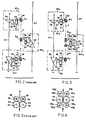
- a modified roll stand MST3 in accordance with the present invention is shown in place of the conventional roll stand ST3.
- the modified stand includes the previously described set of bevel gears 28, 30 for establishing a drive connection between line shaft 24 and one of two parallel intermediate drive shafts 32.
- the intermediate drive shafts are again mechanically interconnected by intermeshed spur gears 34.
- First and second pairs of roll shafts 36a, 36b are arranged respectively on the upstream and downstream sides of the intermediate drive shafts 32.
- the roll shafts 36a, 36b are provided respectively with pinion gears 38a, 38b which mesh with respective ones of the spur gears 34 arranged therebetween.
- the resulting arrangement may therefore be described as a "six gear cluster".
- the roll shafts 36a, 36b respectively carry work rolls R 3a and R 3b .
- the work rolls R 3a are adapted to size a round received from the preceding roll stand ST2.
- the term "sizing” connotes the taking of a reduction on the order of 0.2 to 10% in one pass, which is relatively light in comparison to the normal average reduction on the order of 20% taken in the immediately preceding roll stand ST2.
- the round process sections When rolling with normal average 20% reductions in an oval-round pass sequence, the round process sections exhibit a tendency to twist. Such twisting is resisted by the stabilizing effect of the downstream oval roll passes.
- the sizing pass it is essential that the sizing pass be located as closely as possible to the preceding roll pass in order to effect sizing before twisting can take place.
- the present invention satisfies this criteria by providing a spacing "A" between the sizing rolls R 3a and the preceding rolls R2 on the order of 100-150 mm., which is substantially less than the normal stand spacing "C".
- the thus sized round can be taken as the finished product of the mill, in which event the other pair of rolls R 3b of the modified stand as well as the rolls R4 - R10 of the remaining stands are dummied.
- the thus sized round may continue to be rolled through rolls R 3b and one or more succeeding roll passes to produce a progressively smaller round which because of the intermediate sizing operation at rolls R 3a , will also be characterized by improved tolerances, although probably not to the extent required to qualify the product as a precision round.
- FIG. 7 Another embodiment of the invention is illustrated in Figure 7.
- the last stand ST10 and the Cardan shaft segment 24 a have been replaced by modified stands MST10 and MST11. Except for their modified external configurations and different gear ratios, the stands MST10 and MST11 are characterized by the same basic design as the previously described modified stand MST3. This embodiment offers the following possibilities:
Landscapes
- Engineering & Computer Science (AREA)
- Mechanical Engineering (AREA)
- Metal Rolling (AREA)
- Buildings Adapted To Withstand Abnormal External Influences (AREA)
- Crushing And Grinding (AREA)
- Manufacturing Of Printed Circuit Boards (AREA)
- Laminated Bodies (AREA)
- Manufacturing Of Electric Cables (AREA)
Applications Claiming Priority (2)
| Application Number | Priority Date | Filing Date | Title |
|---|---|---|---|
| US728604 | 1991-07-11 | ||
| US07/728,604 US5152165A (en) | 1991-07-11 | 1991-07-11 | Rolling mill |
Publications (2)
| Publication Number | Publication Date |
|---|---|
| EP0543479A1 true EP0543479A1 (de) | 1993-05-26 |
| EP0543479B1 EP0543479B1 (de) | 1996-05-08 |
Family
ID=24927528
Family Applications (1)
| Application Number | Title | Priority Date | Filing Date |
|---|---|---|---|
| EP92305939A Expired - Lifetime EP0543479B1 (de) | 1991-07-11 | 1992-06-26 | Walzwerk |
Country Status (13)
| Country | Link |
|---|---|
| US (1) | US5152165A (de) |
| EP (1) | EP0543479B1 (de) |
| JP (1) | JP2546951B2 (de) |
| KR (1) | KR100231280B1 (de) |
| CN (1) | CN1036252C (de) |
| AT (1) | ATE137691T1 (de) |
| AU (1) | AU649341B2 (de) |
| BR (1) | BR9202572A (de) |
| CA (1) | CA2071572C (de) |
| DE (1) | DE69210552T2 (de) |
| MX (1) | MX9204079A (de) |
| TW (1) | TW204307B (de) |
| ZA (1) | ZA924583B (de) |
Cited By (4)
| Publication number | Priority date | Publication date | Assignee | Title |
|---|---|---|---|---|
| EP0581497A1 (de) * | 1992-07-27 | 1994-02-02 | Morgan Construction Company | Walzwerk mit einem eine Drehzahlverstellmöglichkeit aufweisenden Fertigwalzblock |
| EP0879654A1 (de) * | 1997-05-21 | 1998-11-25 | DANIELI & C. OFFICINE MECCANICHE S.p.A. | Walzwerkelement und damit erhaltenes Walzwerk |
| EP0768124A3 (de) * | 1995-10-14 | 2001-01-31 | Daido Tokushuko Kabushiki Kaisha | Verfahren und Vorrichtung zur Herstellung von Draht |
| WO2006010616A1 (en) * | 2004-07-28 | 2006-02-02 | Vai Pomini S.R.L. | Finishing monoblock with optimised transmission ratio for a billet rolling plant |
Families Citing this family (12)
| Publication number | Priority date | Publication date | Assignee | Title |
|---|---|---|---|---|
| JP3250087B2 (ja) * | 1993-08-24 | 2002-01-28 | 大同特殊鋼株式会社 | 圧延機 |
| US5595083A (en) * | 1994-08-01 | 1997-01-21 | Morgan Construction Company | Modular rolling mill |
| US5832765A (en) * | 1995-10-14 | 1998-11-10 | Daido Tokushuko Kabushiki Kaisha | Method and an apparatus for manufacturing wire |
| JP3535946B2 (ja) * | 1997-01-10 | 2004-06-07 | 株式会社神戸製鋼所 | 条鋼圧延機 |
| RU2212961C1 (ru) * | 2001-01-25 | 2003-09-27 | Морган Констракшн Компани | Секция чистовой прокатки прокатного стана |
| US6546776B2 (en) * | 2001-01-31 | 2003-04-15 | Morgan Construction Company | High speed finishing block |
| RU2220791C2 (ru) * | 2001-01-31 | 2004-01-10 | Морган Констракшн Компани | Высокоскоростной блок чистовой прокатки |
| RU2264877C2 (ru) * | 2004-01-28 | 2005-11-27 | Открытое акционерное общество "Магнитогорский металлургический комбинат" | Профилегибочный стан легкого типа |
| US7191629B1 (en) * | 2006-04-13 | 2007-03-20 | Morgan Construction Company | Modular rolling mill |
| US7523632B2 (en) * | 2007-02-15 | 2009-04-28 | Morgan Construction Company | Modular rolling mill |
| RU2639198C2 (ru) * | 2012-05-07 | 2017-12-20 | ПРАЙМЕТАЛЗ ТЕКНОЛОДЖИЗ ЮЭсЭй ЭлЭлСи | Модульный прокатный стан |
| WO2014052222A1 (en) | 2012-09-25 | 2014-04-03 | Siemens Industry, Inc. | Modular finishing mill |
Citations (5)
| Publication number | Priority date | Publication date | Assignee | Title |
|---|---|---|---|---|
| DE632217C (de) * | 1934-06-05 | 1936-07-04 | Demag Akt Ges | Im offenen Strang liegende Walzenstrasse |
| GB975510A (en) * | 1960-08-01 | 1964-11-18 | Ilario Properzi | A rolling mill for metal bars and wires |
| FR2096586A7 (de) * | 1970-06-30 | 1972-02-18 | Demag Ag | |
| FR2403119A1 (fr) * | 1977-09-17 | 1979-04-13 | Kocks Gmbh Friedrich | Train de laminoir pour le laminage de fils ou produits en barre |
| US4537055A (en) * | 1984-06-20 | 1985-08-27 | Morgan Construction Company | Single strand block-type rolling mill |
Family Cites Families (12)
| Publication number | Priority date | Publication date | Assignee | Title |
|---|---|---|---|---|
| FR1016392A (fr) * | 1950-03-27 | 1952-11-10 | Kocks Gmbh Friedrich | Laminoir à larges plats et laminoir à tubes |
| SU130469A1 (ru) * | 1959-11-26 | 1959-11-30 | Н.И. Баимов | Способ реверсивной прокатки слитков в одной плоскости |
| DE1813331A1 (de) * | 1968-12-07 | 1970-06-25 | Siemag Siegener Maschinenebau | Universal-Planetenwalzwerk |
| US3641797A (en) * | 1970-02-05 | 1972-02-15 | American Metal Climax Inc | Stretcher leveling system |
| US3733847A (en) * | 1971-03-24 | 1973-05-22 | Pennwalt Corp | Direct contact halocarbon freezant apparatus |
| US4024746A (en) * | 1975-01-28 | 1977-05-24 | Demag Aktiengesellschaft | Stand gearing arrangement for the rolls of a continuous rolling mill |
| DD145502A1 (de) * | 1979-08-17 | 1980-12-17 | Kurt Wesendorf | Antrieb fuer duowalzgerueste |
| DE3001343C2 (de) * | 1980-01-16 | 1982-05-27 | Kocks Technik GmbH & Co, 4000 Düsseldorf | Getriebe zum Antrieb der Walzen einer Walzstraße |
| SU1253688A1 (ru) * | 1985-01-28 | 1986-08-30 | Челябинский Политехнический Институт Им.Ленинского Комсомола | Зубчато-цепной привод |
| JPS61186105A (ja) * | 1985-02-15 | 1986-08-19 | Nippon Steel Corp | 圧延機 |
| ATE48097T1 (de) * | 1985-07-18 | 1989-12-15 | Krupp Gmbh | Walzblock. |
| SU1315057A1 (ru) * | 1985-10-30 | 1987-06-07 | Всесоюзный научно-исследовательский и проектно-конструкторский институт металлургического машиностроения им.А.И.Целикова | Привод горизонтальной прокатной клети |
-
1991
- 1991-07-11 US US07/728,604 patent/US5152165A/en not_active Expired - Fee Related
-
1992
- 1992-06-18 CA CA002071572A patent/CA2071572C/en not_active Expired - Fee Related
- 1992-06-22 ZA ZA924583A patent/ZA924583B/xx unknown
- 1992-06-26 EP EP92305939A patent/EP0543479B1/de not_active Expired - Lifetime
- 1992-06-26 AT AT92305939T patent/ATE137691T1/de not_active IP Right Cessation
- 1992-06-26 DE DE69210552T patent/DE69210552T2/de not_active Expired - Fee Related
- 1992-07-02 JP JP4175650A patent/JP2546951B2/ja not_active Expired - Fee Related
- 1992-07-07 TW TW081105392A patent/TW204307B/zh active
- 1992-07-10 KR KR1019920012285A patent/KR100231280B1/ko not_active Expired - Fee Related
- 1992-07-10 BR BR929202572A patent/BR9202572A/pt not_active IP Right Cessation
- 1992-07-10 CN CN92105579A patent/CN1036252C/zh not_active Expired - Fee Related
- 1992-07-10 AU AU19587/92A patent/AU649341B2/en not_active Ceased
- 1992-07-10 MX MX9204079A patent/MX9204079A/es not_active IP Right Cessation
Patent Citations (5)
| Publication number | Priority date | Publication date | Assignee | Title |
|---|---|---|---|---|
| DE632217C (de) * | 1934-06-05 | 1936-07-04 | Demag Akt Ges | Im offenen Strang liegende Walzenstrasse |
| GB975510A (en) * | 1960-08-01 | 1964-11-18 | Ilario Properzi | A rolling mill for metal bars and wires |
| FR2096586A7 (de) * | 1970-06-30 | 1972-02-18 | Demag Ag | |
| FR2403119A1 (fr) * | 1977-09-17 | 1979-04-13 | Kocks Gmbh Friedrich | Train de laminoir pour le laminage de fils ou produits en barre |
| US4537055A (en) * | 1984-06-20 | 1985-08-27 | Morgan Construction Company | Single strand block-type rolling mill |
Cited By (5)
| Publication number | Priority date | Publication date | Assignee | Title |
|---|---|---|---|---|
| EP0581497A1 (de) * | 1992-07-27 | 1994-02-02 | Morgan Construction Company | Walzwerk mit einem eine Drehzahlverstellmöglichkeit aufweisenden Fertigwalzblock |
| EP0768124A3 (de) * | 1995-10-14 | 2001-01-31 | Daido Tokushuko Kabushiki Kaisha | Verfahren und Vorrichtung zur Herstellung von Draht |
| EP0879654A1 (de) * | 1997-05-21 | 1998-11-25 | DANIELI & C. OFFICINE MECCANICHE S.p.A. | Walzwerkelement und damit erhaltenes Walzwerk |
| WO2006010616A1 (en) * | 2004-07-28 | 2006-02-02 | Vai Pomini S.R.L. | Finishing monoblock with optimised transmission ratio for a billet rolling plant |
| CN1993190B (zh) * | 2004-07-28 | 2010-06-16 | Vai波米尼有限公司 | 用于坯料轧制设备的具有最佳传动比的精加工整体单元 |
Also Published As
| Publication number | Publication date |
|---|---|
| JP2546951B2 (ja) | 1996-10-23 |
| CA2071572C (en) | 1995-05-16 |
| DE69210552T2 (de) | 1996-09-19 |
| ZA924583B (en) | 1993-03-31 |
| CN1036252C (zh) | 1997-10-29 |
| TW204307B (de) | 1993-04-21 |
| ATE137691T1 (de) | 1996-05-15 |
| KR100231280B1 (ko) | 1999-11-15 |
| AU649341B2 (en) | 1994-05-19 |
| MX9204079A (es) | 1993-04-01 |
| US5152165A (en) | 1992-10-06 |
| CN1070851A (zh) | 1993-04-14 |
| BR9202572A (pt) | 1993-03-16 |
| AU1958792A (en) | 1993-01-14 |
| DE69210552D1 (de) | 1996-06-13 |
| JPH05185101A (ja) | 1993-07-27 |
| EP0543479B1 (de) | 1996-05-08 |
Similar Documents
| Publication | Publication Date | Title |
|---|---|---|
| EP0543479B1 (de) | Walzwerk | |
| EP0512735B1 (de) | Verfahren zum kontinuierlichen Warmwalzen langer Stahlprodukte | |
| EP1519798B1 (de) | Verfahren und giesswalzanlage zum semi-endloswalzen oder endloswalzen durch giessen eines metalls insbesondere eines stahlstrangs, der nach dem erstarren bei bedarf quergeteilt wird | |
| AU2007200620A1 (en) | Modular rolling mill | |
| AU660552B2 (en) | Finishing block with dual speed sizing capability | |
| DE4308449C2 (de) | Walzblock zum Walzen von metallischen Stäben oder Draht | |
| DE2418454B2 (de) | Mehradrige drahtstrasse fuer hohe produktionsleistung und grosse bundgewichte | |
| DE2437684C2 (de) | Walzwerk zur Herstellung von Draht und Rippenstahl | |
| DE2653660A1 (de) | Drahtziehmaschine | |
| DE69705555T2 (de) | Verfahren zum Walzen von Langprodukten und Walzstrasse zur Durchführung dieses Verfahrens | |
| EP0560115B1 (de) | Verfahren und Walzwerk zum Präzisionswalzen von Draht bzw. von Walzgut mit Rundquerschnitt | |
| EP0560093A1 (de) | Feinstahl-/Drahtstrasse | |
| US6161412A (en) | Multi-strand finishing block | |
| EP0845310A1 (de) | Drahtkühlung | |
| DE2833456C2 (de) | Antriebsvorrichtung für eine Walzstraße zum Streckreduzieren von Rohren | |
| US3546915A (en) | Drives for multistand universal rolling mills | |
| DE1427920C3 (de) | Getriebe zum Antrieb eines vielgerüstfgen Universalwalzwerkes, insbesondere eines Draht- oder Rohrreduzierwalzwerkes | |
| SU1585027A1 (ru) | Непрерывный прокатный стан | |
| DE2927731C2 (de) | Kühlstrecke zum Abkühlen von warmgewalztem Draht | |
| DE502766C (de) | Kontinuierliche Walzenstrasse mit elektrischem Antrieb | |
| US320237A (en) | Rolling-mill for wire rods | |
| DD206087A1 (de) | Verfahren und einrichtung zur herstellung von feinstahl | |
| DE19936140A1 (de) | Verfahren zur Regelung des Draht-Zuges zwischen Fertigblock und Nachblock in Drahtwalzstraßen | |
| DE3725912A1 (de) | Verfahren zum warmwalzen von stabfoermigem walzgut | |
| DE1093764B (de) | Walzenstrasse zum gleichzeitigen Auswalzen von Feineisen oder Draht in zwei Adern |
Legal Events
| Date | Code | Title | Description |
|---|---|---|---|
| PUAI | Public reference made under article 153(3) epc to a published international application that has entered the european phase |
Free format text: ORIGINAL CODE: 0009012 |
|
| AK | Designated contracting states |
Kind code of ref document: A1 Designated state(s): AT BE CH DE DK ES FR GB GR IT LI LU NL PT SE |
|
| 17P | Request for examination filed |
Effective date: 19931027 |
|
| 17Q | First examination report despatched |
Effective date: 19940519 |
|
| GRAH | Despatch of communication of intention to grant a patent |
Free format text: ORIGINAL CODE: EPIDOS IGRA |
|
| GRAA | (expected) grant |
Free format text: ORIGINAL CODE: 0009210 |
|
| ITF | It: translation for a ep patent filed | ||
| AK | Designated contracting states |
Kind code of ref document: B1 Designated state(s): AT BE CH DE DK ES FR GB GR IT LI LU NL PT SE |
|
| PG25 | Lapsed in a contracting state [announced via postgrant information from national office to epo] |
Ref country code: NL Free format text: LAPSE BECAUSE OF FAILURE TO SUBMIT A TRANSLATION OF THE DESCRIPTION OR TO PAY THE FEE WITHIN THE PRESCRIBED TIME-LIMIT Effective date: 19960508 Ref country code: LI Free format text: LAPSE BECAUSE OF FAILURE TO SUBMIT A TRANSLATION OF THE DESCRIPTION OR TO PAY THE FEE WITHIN THE PRESCRIBED TIME-LIMIT Effective date: 19960508 Ref country code: GR Free format text: LAPSE BECAUSE OF FAILURE TO SUBMIT A TRANSLATION OF THE DESCRIPTION OR TO PAY THE FEE WITHIN THE PRESCRIBED TIME-LIMIT Effective date: 19960508 Ref country code: FR Effective date: 19960508 Ref country code: ES Free format text: THE PATENT HAS BEEN ANNULLED BY A DECISION OF A NATIONAL AUTHORITY Effective date: 19960508 Ref country code: DK Effective date: 19960508 Ref country code: CH Free format text: LAPSE BECAUSE OF FAILURE TO SUBMIT A TRANSLATION OF THE DESCRIPTION OR TO PAY THE FEE WITHIN THE PRESCRIBED TIME-LIMIT Effective date: 19960508 Ref country code: BE Effective date: 19960508 |
|
| REF | Corresponds to: |
Ref document number: 137691 Country of ref document: AT Date of ref document: 19960515 Kind code of ref document: T |
|
| REF | Corresponds to: |
Ref document number: 69210552 Country of ref document: DE Date of ref document: 19960613 |
|
| PG25 | Lapsed in a contracting state [announced via postgrant information from national office to epo] |
Ref country code: LU Free format text: LAPSE BECAUSE OF NON-PAYMENT OF DUE FEES Effective date: 19960630 |
|
| PG25 | Lapsed in a contracting state [announced via postgrant information from national office to epo] |
Ref country code: PT Effective date: 19960808 |
|
| NLV1 | Nl: lapsed or annulled due to failure to fulfill the requirements of art. 29p and 29m of the patents act | ||
| EN | Fr: translation not filed | ||
| REG | Reference to a national code |
Ref country code: CH Ref legal event code: PL |
|
| PLBE | No opposition filed within time limit |
Free format text: ORIGINAL CODE: 0009261 |
|
| STAA | Information on the status of an ep patent application or granted ep patent |
Free format text: STATUS: NO OPPOSITION FILED WITHIN TIME LIMIT |
|
| 26N | No opposition filed | ||
| REG | Reference to a national code |
Ref country code: GB Ref legal event code: IF02 |
|
| PGFP | Annual fee paid to national office [announced via postgrant information from national office to epo] |
Ref country code: AT Payment date: 20030603 Year of fee payment: 12 |
|
| PGFP | Annual fee paid to national office [announced via postgrant information from national office to epo] |
Ref country code: SE Payment date: 20030619 Year of fee payment: 12 Ref country code: GB Payment date: 20030619 Year of fee payment: 12 |
|
| PGFP | Annual fee paid to national office [announced via postgrant information from national office to epo] |
Ref country code: DE Payment date: 20030630 Year of fee payment: 12 |
|
| PG25 | Lapsed in a contracting state [announced via postgrant information from national office to epo] |
Ref country code: GB Free format text: LAPSE BECAUSE OF NON-PAYMENT OF DUE FEES Effective date: 20040626 Ref country code: AT Free format text: LAPSE BECAUSE OF NON-PAYMENT OF DUE FEES Effective date: 20040626 |
|
| PG25 | Lapsed in a contracting state [announced via postgrant information from national office to epo] |
Ref country code: SE Free format text: LAPSE BECAUSE OF NON-PAYMENT OF DUE FEES Effective date: 20040627 |
|
| PG25 | Lapsed in a contracting state [announced via postgrant information from national office to epo] |
Ref country code: DE Free format text: LAPSE BECAUSE OF NON-PAYMENT OF DUE FEES Effective date: 20050101 |
|
| EUG | Se: european patent has lapsed | ||
| EUG | Se: european patent has lapsed | ||
| GBPC | Gb: european patent ceased through non-payment of renewal fee |
Effective date: 20040626 |
|
| PG25 | Lapsed in a contracting state [announced via postgrant information from national office to epo] |
Ref country code: IT Free format text: LAPSE BECAUSE OF NON-PAYMENT OF DUE FEES;WARNING: LAPSES OF ITALIAN PATENTS WITH EFFECTIVE DATE BEFORE 2007 MAY HAVE OCCURRED AT ANY TIME BEFORE 2007. THE CORRECT EFFECTIVE DATE MAY BE DIFFERENT FROM THE ONE RECORDED. Effective date: 20050626 |