EP0543533B1 - Fer à repasser électrique à vapeur - Google Patents
Fer à repasser électrique à vapeur Download PDFInfo
- Publication number
- EP0543533B1 EP0543533B1 EP92310099A EP92310099A EP0543533B1 EP 0543533 B1 EP0543533 B1 EP 0543533B1 EP 92310099 A EP92310099 A EP 92310099A EP 92310099 A EP92310099 A EP 92310099A EP 0543533 B1 EP0543533 B1 EP 0543533B1
- Authority
- EP
- European Patent Office
- Prior art keywords
- steam
- flow path
- boiler
- flow
- soleplate
- Prior art date
- Legal status (The legal status is an assumption and is not a legal conclusion. Google has not performed a legal analysis and makes no representation as to the accuracy of the status listed.)
- Expired - Lifetime
Links
Images

Classifications
-
- D—TEXTILES; PAPER
- D06—TREATMENT OF TEXTILES OR THE LIKE; LAUNDERING; FLEXIBLE MATERIALS NOT OTHERWISE PROVIDED FOR
- D06F—LAUNDERING, DRYING, IRONING, PRESSING OR FOLDING TEXTILE ARTICLES
- D06F75/00—Hand irons
- D06F75/08—Hand irons internally heated by electricity
- D06F75/24—Arrangements of the heating means within the iron; Arrangements for distributing, conducting or storing the heat
-
- D—TEXTILES; PAPER
- D06—TREATMENT OF TEXTILES OR THE LIKE; LAUNDERING; FLEXIBLE MATERIALS NOT OTHERWISE PROVIDED FOR
- D06F—LAUNDERING, DRYING, IRONING, PRESSING OR FOLDING TEXTILE ARTICLES
- D06F75/00—Hand irons
- D06F75/08—Hand irons internally heated by electricity
- D06F75/10—Hand irons internally heated by electricity with means for supplying steam to the article being ironed
- D06F75/14—Hand irons internally heated by electricity with means for supplying steam to the article being ironed the steam being produced from water in a reservoir carried by the iron
- D06F75/18—Hand irons internally heated by electricity with means for supplying steam to the article being ironed the steam being produced from water in a reservoir carried by the iron the water being fed slowly, e.g. drop by drop, from the reservoir to a steam generator
Definitions
- This invention relates to an electric steam iron and in particular, to a boiler thereof used for generating steam.
- the soleplate temperature must be reduced which sometimes results in water spotting and inadequate heat for the fabric being ironed.
- irons having separate boilers for generating steam, and which are heated and controlled independently of the soleplate have been designed.
- Examples of irons with separate soleplate and boiler heaters are described in U.S. Patents 2,387,757, 2,499,835, and 3,263,350.
- the addition of a second heater dedicated to the generation of steam has typically increased the elevational profile of the iron, making the iron more expensive to manufacture, and less aesthetically attractive.
- the present invention provides an electric steam iron having a housing; a water reservoir mounted in the housing; the housing further defining a boiler in fluid flow communication with said water reservoir; a soleplate; a heater for said boiler; a heater for said soleplate; fluid control means for regulating the flow of fluid from said water reservoir to said boiler; first and second thermostatic means for respectively independently regulating the operating temperature of said boiler and said soleplate heaters; said boiler comprising a first member in direct contact with said boiler heater for receiving water from said reservoir and transforming said water into a steam, a second member overlying said first member and defining therebetween a first flow path for said steam, and a third member overlying said second member and defining therebetween a second flow path for said steam, said first and second flow paths being in fluid flow communication such that the steam flowing through said second flow path flows in a direction opposite to the steam flowing in said first flow path; and means for distributing the steam flowing from said second flow path through said soleplate.
- electric iron 10 includes a housing 12 formed from a suitable material such as polypropylene.
- An electric cord 14 extends from the rear of the housing 12 and connects the iron 10 to a source of electrical power.
- a water reservoir 16 is mounted or contained in the housing 12.
- the housing 12 includes a handle 15 and a saddle portion 17.
- a control knob 18 is mounted on the saddle portion 17 for regulating the operation of a thermostat 19.
- the thermostat 19 controls the operating temperature of a first heater 28.
- the heater 28 is operatively connected to soleplate 24.
- the temperature of the soleplate may be varied by the user of the iron 10 through appropriate movement of the control knob 18.
- a first control knob 22 is mounted at the top forward portion of the housing 12 and operates to regulate the operation of a fluid control means 23.
- the fluid flow control means 23 meters the flow of fluid from water reservoir 16 into a boiler 30 for a reason that shall be more fully described hereinafter.
- a second control knob 20 is also mounted at the top of the housing 12.
- the control knob 20 operates a pump 25 which is used to inject a relatively large quantity of water into the boiler 30. The water is injected when a surge of steam is desired by the user.
- the pump 25 is also connected to a spray nozzle located at the nose 27 of housing 12.
- the thermostat 19 can be regulated by the user of the iron to vary the temperature of the heater 28 and thus the operating temperature of the soleplate 24.
- Some fabrics, such as cotton, must be ironed at a relatively high temperature to obtain an acceptably ironed garment.
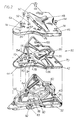
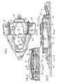
- Iron 10 includes the separate boiler 30, details of which are specifically shown in Figures 2 to 5. Unlike a conventional iron, the boiler 30 has a separate heater 40 which is designed to generate steam at or near saturation temperature.
- the boiler 30 is mounted in the housing 12 and includes a first member 32 having a generally centrally located axially extending portion or passage 34 defined by a vertically upwardly extending generally U-shaped rib 33. Water under control of the fluid control means 23 is metered from the reservoir 16 into the forward section of portion 34 of the first member 32.
- the bottom wall or floor 35 of member 32 is canted or sloped in a forward direction approximately 5 degrees relative to a horizontal line.
- a generally U-shaped heater 40 provides sufficient heat to transform the water into steam.
- the member 32 includes a generally flat ledge-like surface 83 for mounting a single set-point thermostat 82.
- the thermostat 82 regulates the operation of heater 40, and is electrically separate from the thermostat 19. Thus the operation of the thermostats are independent of each other and the heaters 28 and 40 are independently controlled.
- the boiler 30 includes a second member 44 which overlies first member 32.
- Member 44 in combination with first member 32 defines a first flow path for the steam generated in the passage 34.
- the member 44 includes an opening 38 which is aligned with the rear portion of the passage 34.
- An inclined baffle 36 extends upwardly from the opening 38 and is axially aligned therewith.
- the member 44 also includes a fluid flow opening 54 and a pair of fluid flow slots 56. The purposes of the flow opening 54 and slots 56 shall be more fully explained hereinafter.
- the boiler 30 includes a third member 46 which is provided in overlying relationship with the member 44.
- the member 46 includes an inverted cuplike element 48 in general vertical alignment with the inclined baffle 36 and defining therebetween a second steam flow passage 72.
- the steam flow through the first passage 34 is in a direction opposite to the steam flow through the second passage 72.
- the inclined baffle 36 directs the steam upwardly as the steam leaves the first flow passage 34 and enters the second flow passage 72.
- the element 48 includes a pair of laterally extending wings 50 which define lateral extensions for the flow of steam in the second flow passage 72.
- the lateral extensions 50 are in vertical alignment with the slots 56 provided in the second member 44.
- the slots 56 in turn are in alignment with the generally U-shaped channel 58 in the member 32.
- the member 46 also includes the flow opening 52 vertically aligned with the opening 54 of the member 44.
- the fluid flow control means 23 regulates the flow of fluid from the reservoir 16 through the flow openings 52 and 54 into the passage 34 of the boiler 30.
- the member 46 includes a further flow opening 76 in vertical alignment with the flow opening 78 in the member 44.
- the opening 76 communicates with the reservoir 16 under control of the pump 23.
- the pump 25 is activated and water is injected from the reservoir 16, through the aligned openings 76 and 78 into a channel 80 formed about the top surface of the heater 40.
- the water is directly heated by the heater 40 and is transformed into steam to satisfy the user's requirements for a surge of steam.
- the steam flowing in the channel 80 exits therefrom to mix with the steam formed in the passage 34.
- the member 32 includes a generally U-shaped rib 88 defining a chamber.
- the members 44 and 46 include the openings 84 and 86 respectively.
- a tube 87 (shown in phantom in Figure 3) runs from the chamber in the member 32 to the air space formed in the top of the reservoir 16.
- a rib 88 prevents water from entering into the bottom of the tube. The tube equalizes the pressure between the boiler 30 and the reservoir 16.
- Steam flowing through the second passage 72 flows outwardly in each direction via the laterally extending wings 50 and thence passes downwardly through the openings 56 into the channel 58.
- the steam exits from the channel 58 via a slot 60 which communicates with the soleplate 24.
- the steam is distributed from the soleplate via a plurality of orifices 26 which are formed in the lower surface of the soleplate.
- the orificies 26 communicate with a steam exit chamber 68 formed between the lower surface of the member 32 and the top surface of the soleplate 24.
- Suitable steam seals 42 between adjoining surfaces of the members 32, 44 and 46 may be obtained via liquid injection molding or sheet stampings.
- the members forming the boiler 30 are joined together via fastening means 64 such as screws, rivets or staking, to upstanding posts which extend through the vertically aligned openings 74, 70 and 66 formed respectively in the members 46, 44 and 32.
- the bottom surface of the member 32 and the top surface of the soleplate 24 define the chamber 68.
- Suitable sealing material such as a liquid injection moldable gasket is placed at interfaces 96 and 98 to prevent loss of steam from the chamber 68 and to prevent significant heat transfer from the soleplate 24 to the member 32.
- the boiler is only connected to and supported by the soleplate at two points, namely via screws, 94 and 92.
- the user of the iron 10 regulates the supply of wattage to the heater 28 to obtain a desired soleplate temperature in accordance with the specific temperature requirements of the fabric being ironed.
- the control knob 22 is actuated to cause the fluid control means 23 to supply water from the reservoir 16 to the first flow passage 34 formed in the member 32 of the boiler 30.
- the water from the water reservoir 16 flows through the opening 52 formed in the plate 46 and the opening 54 formed in the member 44, into the passage 34.
- the floor 35 is sloped forwardly approximately 5 degrees. This slope functions to prevent water from migrating towards the opening 38 and percolating therethrough into the second flow passage 72.
- the wattage supplied to the dedicated heater 40 of the boiler 30 is designed to convert the water to steam at or near saturation conditions.
- the steam thus formed therefore has some water vapour entrained in the gaseous molecules. It has been determined that this water vapour relaxes the fabric of the garment being ironed to improve the quality of the finished ironed garment.
- the steam flowing through the passage 34 exits through the opening 38 and is directed by the inclined baffle member 36 upwardly into the second flow passage 72.
- the steam contains a certain quantity of water vapour, it is not desirable that the steam contains, large droplets or slugs of water. It has been found that large droplets of water can cause undesirable water spotting of the fabric being ironed.
- the inclined baffle member 36 serves two purposes. The first is to cause the steam to change direction as it passes from the first flow passage into the second flow passage. The change in direction of the steam flow results in separation of large droplets of water, from the steam vapour. Further, the inclination of the baffle 36 results in the steam flow being directed vertically upwards.
- the second steam flow passage 72 channels the steam flow in a counter-flow direction relative to the steam flowing through the passage 34.
- the steam in the second passage is in heat transfer relation with the steam flowing in the first passage.
- the somewhat warmer temperature steam in the first flow passage transfers heat to the somewhat colder steam flowing through the second flow passage to maintain the temperature of the steam in the second passage at or near its original temperature level and thereby prevent the formation of excessive water condensation.
- the steam flowing through the second flow path 72 defined by the top surface of the baffle member 36 and the lower surface of the element 48 passes outwardly into the wings 50, and then downwardly through the openings 56 formed in the member 44.
- the steam then enters, the channel 58 in the first member 32 and passes outwardly from the member via the slot 60 for distribution through the orifices 26 formed in the bottom surface of the soleplate.
- the slots 56 are generally aligned with the heater 40. Any water droplets remaining in the steam transmitted through the slots 56 should be vaporized as a result of direct contact with the heater 40.
- the boiler 30 is effective in producing steam at or near saturation temperature. Due to the compact size of the boiler, the boiler does not significantly increase the elevational profile of the iron. The tortuous path established for the flow of steam through boiler 30 effectively separates any large droplets or slugs of water.
Landscapes
- Engineering & Computer Science (AREA)
- Textile Engineering (AREA)
- Irons (AREA)
- Instantaneous Water Boilers, Portable Hot-Water Supply Apparatuses, And Control Of Portable Hot-Water Supply Apparatuses (AREA)
Claims (12)
- Fer électrique à vapeur (10) comportant :un carter (12)un réservoir d'eau (16) monté dans le carter (12),des moyens comportant une chaudière (30) montée à l'intérieur du carter, en communication de fluide avec le réservoir d'eau,une semelle (24) reliée au carter (12),un premier dispositif de chauffage (40) actionné électriquement etun second dispositif de chauffage (28) actionné électriquement, monté dans la semelle,caractérisé en ce que le premier dispositif de chauffage actionné électriquement (40) est monté dans la chaudière (30) et le second dispositif de chauffage (28) actionné électriquement est monté dans la semelle, lequel fer comporte en outre des moyens de commande de fluide (23) pour réguler l'écoulement de fluide depuis le réservoir d'eau (16) vers la chaudière (30),des premiers moyens thermostatiques (82) pour réguler de manière indépendante la température de fonctionnement du dispositif de chauffage de chaudière et des seconds moyens thermostatiques (19) pour réguler de manière indépendante la température de fonctionnement du dispositif de chauffage de semelle,la chaudière comportant un premier élément (32) pour recevoir de l'eau provenant du réservoir et comportant le premier dispositif de chauffage monté à l'intérieur de celui-ci pour transformer l'eau en vapeur, un deuxième élément (44) recouvrant le premier élément et délimitant entre eux un premier passage d'écoulement pour la vapeur engendrée dans le premier élément, et un troisième élément (46) recouvrant le deuxième élément et délimitant entre eux un second trajet d'écoulement (72) pour la vapeur, le premier et le second trajet d'écoulement étant en communication de fluide de telle sorte que la vapeur s'écoulant dans le second trajet d'écoulement (72) s'écoule dans une direction opposée à la vapeur s'écoulant dans le premier trajet d'écoulement, et des moyens (26) pour répartir à travers la semelle la vapeur s'écoulant depuis le second trajet d'écoulement (72).
- Fer à vapeur selon la revendication 1, caractérisé en ce que le troisième élément (46) comporte une paire d'ailes (50) s'étendant latéralement, en communication de fluide avec le second trajet d'écoulement (72) et le deuxième élément (44) comporte au moins une ouverture (56) alignée avec chaque aile.
- Fer à vapeur selon la revendication 1 ou 2, caractérisé en ce que le premier élément (32) comporte un canal (58) aligné avec les ouvertures (56) formées dans le deuxième élément (44) de sorte que la vapeur s'écoulant à travers le second trajet d'écoulement (72) est dirigée jusqu'à l'intérieur du canal (58) à travers les ouvertures (56), et des moyens (66) pour mettre en communication le canal avec les moyens de répartition de la vapeur.
- Fer à vapeur selon l'une quelconque des revendications précédentes, caractérisé en ce que le deuxième élément (44) comporte un élément (36) formant déflecteur incliné pour diriger la vapeur sortant du premier trajet d'écoulement vers le haut le long du second trajet d'écoulement (72).
- Fer à vapeur selon l'une quelconque des revendications précédentes, caractérisé en ce que le premier élément (32) a une paroi de fond (35) en pente selon un angle d'à peu près 5 degrés par rapport à l'horizontale.
- Fer électrique selon l'une quelconque des revendications précédentes, caractérisé en ce que le premier dispositif de chauffage (40) actionné électriquement est relié de manière opérationnelle à la chaudière (30),le second dispositif de chauffage (28) actionné électriquement est relié de manière opérationnelle à la semelle (24), etla chaudière (30) comporte un premier élément (32) en contact direct avec le dispositif de chauffage de chaudière (40) et comportant une première partie (34) destinée à recevoir l'eau provenant du réservoir d'eau et formant un tronçon de chaudière pour convertir l'eau en vapeur, un deuxième élément (44) verticalement espacé au-dessus du premier élément (32) pour délimiter entre eux un premier trajet d'écoulement s'étendant longitudinalement pour la vapeur formée dans le tronçon de chaudière (34), un troisième élément (46) verticalement espacé au-dessus du deuxième élément (44) pour délimiter entre eux un second trajet d'écoulement (72) s'étendant longitudinalement, la fin du premier trajet d'écoulement communiquant avec le début du second trajet d'écoulement (72) de sorte que la vapeur s'écoulant à travers le second trajet d'écoulement (72) se déplace dans une direction opposée à l'écoulement de vapeur à travers le premier trajet d'écoulement, le troisième élément (46) comportant une paire d'ailes (50) s'étendant latéralement, en communication de fluide avec la fin du second trajet d'écoulement (72), pour définir des prolongements latéraux de trajet d'écoulement pour la vapeur sortant du second trajet d'écoulement (72), et des moyens (56, 58, 26) en communication de fluide avec les ailes (50) et la semelle (24) pour répartir à travers la semelle (24) la vapeur provenant des ailes (50).
- Fer à vapeur selon la revendication 6, caractérisé en ce que le premier élément (32) comporte un canal (58) en communication de fluide avec les ailes, et des moyens (60) pour mettre en communication le canal avec les moyens de répartition de vapeur.
- Fer à vapeur selon la revendication 6 ou 7, caractérisé en ce que le deuxième élément (44) comporte un élément (36) formant déflecteur incliné pour diriger la vapeur sortant du premier trajet d'écoulement vers le haut le long du second trajet d'écoulement (72).
- Chaudière (30) pour engendrer de la vapeur dans un fer électrique à vapeur (10) ayant un réservoir d'eau (16) et une semelle (24), laquelle chaudière (30) comporte :
un premier élément (32) pour recevoir l'eau provenant du réservoir d'eau (16) et ayant un dispositif de chauffage actionné électriquement (40) pour convertir l'eau en vapeur,
caractérisé en ce que la chaudière (30) comporte en outredes moyens (34) formant passage agencé dans le premier élément pour diriger la vapeur dans une première direction axiale,un deuxième élément (44) recouvrant le premier élément et comportant une première ouverture (38) alignée avec une extrémité des moyens (34) formant passage et un élément (36) formant déflecteur incliné s'étendant axialement, ayant une extrémité inférieure alignée avec l'ouverture,un troisième élément (46) recouvrant le deuxième élément (44) pour définir entre eux un second trajet d'écoulement (72) pour la vapeur, le second trajet d'écoulement (72) étant en communication avec la première ouverture (38) et étant verticalement au-dessus des moyens (34) formant passage pour diriger la vapeur s'écoulant à travers celui-ci dans une direction axiale opposée à la direction d'écoulement de la vapeur à travers les moyens (34) formant passage, etdes moyens de répartition de fluide (50, 56, 58, 60) communiquant avec le second trajet d'écoulement (72) pour répartir la vapeur s'écoulant à travers le trajet d'écoulement vers la semelle (24). - Chaudière selon la revendication 9, caractérisée en ce que le troisième élément (46) comporte une paire d'ailes s'étendant latéralement (50) en communication de fluide avec le second trajet d'écoulement (72) et le deuxième élément comporte au moins une ouverture (56) alignée avec chaque aile.
- Chaudière selon la revendication 9 ou 10, caractérisée en ce que le premier élément (32) comporte un canal (58) aligné avec les ouvertures (56) formées dans le deuxième élément (44) à travers lesquelles la vapeur s'écoulant depuis le second trajet d'écoulement (72) est dirigée jusqu'à l'intérieur du canal.
- Chaudière selon l'une quelconque des revendications 9 à 11, caractérisée en ce que le premier élément (32) a une paroi de fond (34) en pente selon un angle d'à peu près 5 degrés par rapport à l'horizontale.
Applications Claiming Priority (2)
| Application Number | Priority Date | Filing Date | Title |
|---|---|---|---|
| US07/796,511 US5279054A (en) | 1991-11-21 | 1991-11-21 | Steam iron including double boiler portions, heaters, and thermostat |
| US796511 | 1991-11-21 |
Publications (2)
| Publication Number | Publication Date |
|---|---|
| EP0543533A1 EP0543533A1 (fr) | 1993-05-26 |
| EP0543533B1 true EP0543533B1 (fr) | 1997-01-08 |
Family
ID=25168357
Family Applications (1)
| Application Number | Title | Priority Date | Filing Date |
|---|---|---|---|
| EP92310099A Expired - Lifetime EP0543533B1 (fr) | 1991-11-21 | 1992-11-04 | Fer à repasser électrique à vapeur |
Country Status (3)
| Country | Link |
|---|---|
| US (1) | US5279054A (fr) |
| EP (1) | EP0543533B1 (fr) |
| DE (1) | DE69216561T2 (fr) |
Families Citing this family (39)
| Publication number | Priority date | Publication date | Assignee | Title |
|---|---|---|---|---|
| USD370104S (en) | 1994-04-18 | 1996-05-21 | Calor S.A. | Electric iron |
| USD366544S (en) | 1994-11-30 | 1996-01-23 | Choi L Wai | Iron |
| US5628131A (en) * | 1995-12-18 | 1997-05-13 | Black & Decker Inc. | Steam surge system for an electric steam iron |
| US5704143A (en) * | 1996-08-19 | 1998-01-06 | Black & Decker Inc. | Dual surge iron with steam generating areas |
| US5829175A (en) * | 1996-09-20 | 1998-11-03 | Black & Decker Inc. | Steam iron with all temperature steam production |
| US5922228A (en) * | 1997-01-10 | 1999-07-13 | Hp Intellectual Corp. | Heat spacer for iron |
| FR2766502B1 (fr) * | 1997-07-22 | 1999-09-17 | Seb Sa | Fer comportant deux moyens de chauffe avec un mode d'asservissement en temperature particulier |
| FR2815649B1 (fr) * | 2000-10-24 | 2003-01-03 | Rowenta Werke Gmbh | Fer avec fonction de surplus de vapeur |
| US6953912B2 (en) * | 2001-11-21 | 2005-10-11 | Celaya Emparanza Y Galdos, Internacional, S.A. | Domestic steam iron with autonomous steam assembly heated by separate heating element |
| CN2530971Y (zh) * | 2001-12-31 | 2003-01-15 | 广东德豪润达电气股份有限公司 | 一种低温蒸汽电熨斗 |
| CN100554567C (zh) * | 2003-12-16 | 2009-10-28 | 皇家飞利浦电子股份有限公司 | 具有重量轻的底板和用于加热底板的扁平电阻加热轨道的蒸汽熨斗 |
| BRPI0500228A (pt) * | 2004-01-30 | 2005-09-20 | Celaya Emparanza Galdos Int Sa | Aperfeiçoamentos para ferros a vapor domésticos possuindo uma câmara de vaporização e encaixada com elemento de calor independente |
| US7516567B2 (en) * | 2004-03-29 | 2009-04-14 | Koninklijke Philips Electronics N.V. | Steam ironing device having vortex generation elements for obtaining vortices in the steam flow |
| EP1761669B1 (fr) | 2004-06-23 | 2012-11-21 | Koninklijke Philips Electronics N.V. | Procede de commande de la temperature de repassage pendant un processus de repassage a vapeur et fer a vapeur correspondant |
| DE102004032361B4 (de) * | 2004-07-03 | 2009-12-10 | Braun Gmbh | Verfahren zur Bereitstellung von Dampf und entsprechendes Dampfbügeleisen |
| WO2006069382A2 (fr) * | 2004-12-22 | 2006-06-29 | Conair Corporation | Centrale vapeur pour vetements avec dispositif chauffant a mode d'attente |
| US7389597B1 (en) * | 2007-02-01 | 2008-06-24 | Samson Tsen | Steam iron |
| US7926208B2 (en) * | 2007-02-12 | 2011-04-19 | Applica Consumer Products, Inc. | Fast heat/fast cool iron with steam boiler |
| CN101082173A (zh) * | 2007-06-29 | 2007-12-05 | 浙江月立电器有限公司 | 一种蒸汽电熨斗 |
| CN101082174A (zh) * | 2007-06-29 | 2007-12-05 | 浙江月立电器有限公司 | 一种蒸汽电熨斗 |
| ES2308952B1 (es) * | 2008-07-03 | 2009-11-16 | Electrodomesticos Taurus, S.L. | Plancha de vapor. |
| RU2618969C2 (ru) * | 2011-11-08 | 2017-05-11 | Конинклейке Филипс Н.В. | Утюг с парогенератором |
| EP2674529A1 (fr) * | 2012-06-12 | 2013-12-18 | Koninklijke Philips N.V. | Fer à vapeur avec un écran permeable à la vapeur |
| DE202014011498U1 (de) * | 2013-07-25 | 2021-06-09 | Koninklijke Philips N.V. | Einrichtung zum Erzeugen von Dampf |
| MY182470A (en) | 2014-08-26 | 2021-01-25 | Koninklijke Philips Nv | Steam iron |
| CN106574430B (zh) * | 2014-09-11 | 2018-12-11 | 松下知识产权经营株式会社 | 蒸汽熨斗 |
| CN204982482U (zh) * | 2015-10-08 | 2016-01-20 | 广东新宝电器股份有限公司 | 一种电熨斗 |
| WO2017191123A1 (fr) * | 2016-05-02 | 2017-11-09 | Koninklijke Philips N.V. | Fer à vapeur à agencement de pont thermique |
| FR3060031B1 (fr) * | 2016-12-13 | 2019-12-13 | Seb S.A. | Fer a vapeur comportant un circuit de distribution de vapeur menage dans un corps en contact thermique avec une surface de repassage |
| CN109440429A (zh) * | 2018-11-25 | 2019-03-08 | 缙云县盛达缝制设备有限公司 | 一种蒸汽发生装置 |
| FR3097881B1 (fr) * | 2019-06-28 | 2021-06-04 | Seb Sa | Fer à repasser équipé d’une chambre de vaporisation pourvue d’une surface inclinée |
| US11236463B2 (en) * | 2019-11-21 | 2022-02-01 | Conair Llc | Fabric steamer |
| USD935117S1 (en) | 2019-11-21 | 2021-11-02 | Conair Llc | Handheld garment steamer |
| US11306429B2 (en) | 2020-03-04 | 2022-04-19 | Conair Llc | Garment steaming device |
| USD930925S1 (en) | 2020-03-04 | 2021-09-14 | Conair Corporation | Garment steamer |
| US11629453B2 (en) | 2020-03-04 | 2023-04-18 | Conair Llc | Garment steaming device |
| US11505893B2 (en) | 2020-03-04 | 2022-11-22 | Conair Llc | Garment steaming device |
| US11261561B2 (en) | 2020-03-04 | 2022-03-01 | Conair Llc | Garment steaming device |
| CN219010759U (zh) * | 2022-11-28 | 2023-05-12 | 张莉 | 一种蒸汽电熨斗 |
Family Cites Families (14)
| Publication number | Priority date | Publication date | Assignee | Title |
|---|---|---|---|---|
| CA905833A (en) * | 1972-07-25 | General Electric Company | Steam iron metallic sealing structure | |
| FR541061A (fr) * | 1920-01-25 | 1922-07-22 | Dispositif de fabrication de cylindres en papier par enroulement | |
| US2078061A (en) * | 1935-10-14 | 1937-04-20 | Harry P Cooper | Pressing iron |
| US2437571A (en) * | 1944-12-01 | 1948-03-09 | Waage Gilbert | Steam iron |
| US2837847A (en) * | 1953-11-18 | 1958-06-10 | Gen Mills Inc | Steam iron |
| US2861365A (en) * | 1957-07-02 | 1958-11-25 | Nassau Products Corp | Toy steam irons |
| US3263350A (en) * | 1958-12-18 | 1966-08-02 | Abraham Carlos Salomon | Electric steam iron |
| CA1030055A (fr) * | 1973-12-13 | 1978-04-25 | William E. Davidson | Fer a vapeur |
| NL8200146A (nl) * | 1982-01-15 | 1983-08-01 | Philips Nv | Stoomstrijkijzer. |
| JPS61162996A (ja) * | 1985-01-11 | 1986-07-23 | 松下電器産業株式会社 | スチ−ムアイロン |
| NL8600048A (nl) * | 1986-01-13 | 1987-08-03 | Philips Nv | Stoomstrijkijzer. |
| US5074066A (en) * | 1989-08-17 | 1991-12-24 | Matsushita Electric Industrial Co., Ltd. | Cordless iron having water and electrical supplies responsive to an iron rest |
| FR2654122B1 (fr) * | 1989-11-07 | 1993-07-30 | Moulinex Sa | Fer a repasser electrique. |
| IT1244228B (it) * | 1990-03-08 | 1994-07-08 | Giulia Dassa | Ferro da stiro elettrico ad apparato di vaporizzazione interno |
-
1991
- 1991-11-21 US US07/796,511 patent/US5279054A/en not_active Expired - Lifetime
-
1992
- 1992-11-04 DE DE69216561T patent/DE69216561T2/de not_active Expired - Lifetime
- 1992-11-04 EP EP92310099A patent/EP0543533B1/fr not_active Expired - Lifetime
Also Published As
| Publication number | Publication date |
|---|---|
| US5279054A (en) | 1994-01-18 |
| EP0543533A1 (fr) | 1993-05-26 |
| DE69216561T2 (de) | 1997-04-24 |
| DE69216561D1 (de) | 1997-02-20 |
Similar Documents
| Publication | Publication Date | Title |
|---|---|---|
| EP0543533B1 (fr) | Fer à repasser électrique à vapeur | |
| US6802141B2 (en) | Iron with surge steam function | |
| US3711972A (en) | Steam iron | |
| EP0543534B1 (fr) | Fer à repasser électrique à vapeur | |
| US3599357A (en) | Electric pressing iron | |
| US6953912B2 (en) | Domestic steam iron with autonomous steam assembly heated by separate heating element | |
| US5924224A (en) | Steam iron with anti-drip device | |
| US7603800B2 (en) | Iron with a vertical crease-smoothing function | |
| US4939342A (en) | Electric steam iron with separately heated sole plate and steam chamber | |
| JP4286329B2 (ja) | 洗濯物アイロン掛け装置 | |
| CN108611831B (zh) | 包括彼此之间通过导管连接的蒸汽发生基部和熨斗的蒸汽熨烫设备 | |
| US3001305A (en) | Pressing irons | |
| CA1240611A (fr) | Fer a vapeur a accumulation | |
| US8607483B2 (en) | Iron with external water reservoir | |
| AU671772B2 (en) | Electric steam iron seal | |
| CA1064811A (fr) | Fer a repasser a thermostat | |
| CN108611832B (zh) | 包括熨烫表面,加热底板和蒸发室的熨斗 | |
| CN108611834B (zh) | 包括通过导管彼此连接的蒸汽发生基部和熨斗的蒸汽熨烫设备 | |
| US2777224A (en) | Steam pressing iron | |
| EP3118369B1 (fr) | Structure de fer améliorée | |
| JP4014651B2 (ja) | 水滴防止デバイス付きアイロン | |
| US2837847A (en) | Steam iron | |
| US2918739A (en) | Flatirons | |
| US3497976A (en) | Steam iron water valve wick structure | |
| US3606691A (en) | Steam-powered spray iron |
Legal Events
| Date | Code | Title | Description |
|---|---|---|---|
| PUAI | Public reference made under article 153(3) epc to a published international application that has entered the european phase |
Free format text: ORIGINAL CODE: 0009012 |
|
| AK | Designated contracting states |
Kind code of ref document: A1 Designated state(s): DE FR GB NL |
|
| 17P | Request for examination filed |
Effective date: 19931013 |
|
| 17Q | First examination report despatched |
Effective date: 19950714 |
|
| GRAG | Despatch of communication of intention to grant |
Free format text: ORIGINAL CODE: EPIDOS AGRA |
|
| GRAH | Despatch of communication of intention to grant a patent |
Free format text: ORIGINAL CODE: EPIDOS IGRA |
|
| GRAH | Despatch of communication of intention to grant a patent |
Free format text: ORIGINAL CODE: EPIDOS IGRA |
|
| GRAA | (expected) grant |
Free format text: ORIGINAL CODE: 0009210 |
|
| AK | Designated contracting states |
Kind code of ref document: B1 Designated state(s): DE FR GB NL |
|
| PG25 | Lapsed in a contracting state [announced via postgrant information from national office to epo] |
Ref country code: NL Free format text: LAPSE BECAUSE OF FAILURE TO SUBMIT A TRANSLATION OF THE DESCRIPTION OR TO PAY THE FEE WITHIN THE PRESCRIBED TIME-LIMIT Effective date: 19970108 |
|
| REF | Corresponds to: |
Ref document number: 69216561 Country of ref document: DE Date of ref document: 19970220 |
|
| ET | Fr: translation filed | ||
| ET | Fr: translation filed |
Free format text: CORRECTIONS |
|
| NLV1 | Nl: lapsed or annulled due to failure to fulfill the requirements of art. 29p and 29m of the patents act | ||
| PLBE | No opposition filed within time limit |
Free format text: ORIGINAL CODE: 0009261 |
|
| 26N | No opposition filed | ||
| REG | Reference to a national code |
Ref country code: GB Ref legal event code: IF02 |
|
| PGFP | Annual fee paid to national office [announced via postgrant information from national office to epo] |
Ref country code: DE Payment date: 20091127 Year of fee payment: 18 |
|
| PGFP | Annual fee paid to national office [announced via postgrant information from national office to epo] |
Ref country code: GB Payment date: 20091125 Year of fee payment: 18 Ref country code: FR Payment date: 20091201 Year of fee payment: 18 |
|
| GBPC | Gb: european patent ceased through non-payment of renewal fee |
Effective date: 20101104 |
|
| REG | Reference to a national code |
Ref country code: FR Ref legal event code: ST Effective date: 20110801 |
|
| REG | Reference to a national code |
Ref country code: DE Ref legal event code: R119 Ref document number: 69216561 Country of ref document: DE Effective date: 20110601 Ref country code: DE Ref legal event code: R119 Ref document number: 69216561 Country of ref document: DE Effective date: 20110531 |
|
| PG25 | Lapsed in a contracting state [announced via postgrant information from national office to epo] |
Ref country code: DE Free format text: LAPSE BECAUSE OF NON-PAYMENT OF DUE FEES Effective date: 20110531 |
|
| PG25 | Lapsed in a contracting state [announced via postgrant information from national office to epo] |
Ref country code: FR Free format text: LAPSE BECAUSE OF NON-PAYMENT OF DUE FEES Effective date: 20101130 |
|
| PG25 | Lapsed in a contracting state [announced via postgrant information from national office to epo] |
Ref country code: GB Free format text: LAPSE BECAUSE OF NON-PAYMENT OF DUE FEES Effective date: 20101104 |