EP0543580A2 - Appareil magnéto-optique capable de reproduire l'information enregistrée pendant l'enregistrement - Google Patents
Appareil magnéto-optique capable de reproduire l'information enregistrée pendant l'enregistrement Download PDFInfo
- Publication number
- EP0543580A2 EP0543580A2 EP92310394A EP92310394A EP0543580A2 EP 0543580 A2 EP0543580 A2 EP 0543580A2 EP 92310394 A EP92310394 A EP 92310394A EP 92310394 A EP92310394 A EP 92310394A EP 0543580 A2 EP0543580 A2 EP 0543580A2
- Authority
- EP
- European Patent Office
- Prior art keywords
- magnetic field
- information
- magneto
- recording
- signal
- Prior art date
- Legal status (The legal status is an assumption and is not a legal conclusion. Google has not performed a legal analysis and makes no representation as to the accuracy of the status listed.)
- Granted
Links
Images


Classifications
-
- G—PHYSICS
- G11—INFORMATION STORAGE
- G11B—INFORMATION STORAGE BASED ON RELATIVE MOVEMENT BETWEEN RECORD CARRIER AND TRANSDUCER
- G11B11/00—Recording on or reproducing from the same record carrier wherein for these two operations the methods are covered by different main groups of groups G11B3/00 - G11B7/00 or by different subgroups of group G11B9/00; Record carriers therefor
- G11B11/10—Recording on or reproducing from the same record carrier wherein for these two operations the methods are covered by different main groups of groups G11B3/00 - G11B7/00 or by different subgroups of group G11B9/00; Record carriers therefor using recording by magnetic means or other means for magnetisation or demagnetisation of a record carrier, e.g. light induced spin magnetisation; Demagnetisation by thermal or stress means in the presence or not of an orienting magnetic field
- G11B11/105—Recording on or reproducing from the same record carrier wherein for these two operations the methods are covered by different main groups of groups G11B3/00 - G11B7/00 or by different subgroups of group G11B9/00; Record carriers therefor using recording by magnetic means or other means for magnetisation or demagnetisation of a record carrier, e.g. light induced spin magnetisation; Demagnetisation by thermal or stress means in the presence or not of an orienting magnetic field using a beam of light or a magnetic field for recording by change of magnetisation and a beam of light for reproducing, i.e. magneto-optical, e.g. light-induced thermomagnetic recording, spin magnetisation recording, Kerr or Faraday effect reproducing
- G11B11/10595—Control of operating function
-
- G—PHYSICS
- G11—INFORMATION STORAGE
- G11B—INFORMATION STORAGE BASED ON RELATIVE MOVEMENT BETWEEN RECORD CARRIER AND TRANSDUCER
- G11B11/00—Recording on or reproducing from the same record carrier wherein for these two operations the methods are covered by different main groups of groups G11B3/00 - G11B7/00 or by different subgroups of group G11B9/00; Record carriers therefor
- G11B11/10—Recording on or reproducing from the same record carrier wherein for these two operations the methods are covered by different main groups of groups G11B3/00 - G11B7/00 or by different subgroups of group G11B9/00; Record carriers therefor using recording by magnetic means or other means for magnetisation or demagnetisation of a record carrier, e.g. light induced spin magnetisation; Demagnetisation by thermal or stress means in the presence or not of an orienting magnetic field
- G11B11/105—Recording on or reproducing from the same record carrier wherein for these two operations the methods are covered by different main groups of groups G11B3/00 - G11B7/00 or by different subgroups of group G11B9/00; Record carriers therefor using recording by magnetic means or other means for magnetisation or demagnetisation of a record carrier, e.g. light induced spin magnetisation; Demagnetisation by thermal or stress means in the presence or not of an orienting magnetic field using a beam of light or a magnetic field for recording by change of magnetisation and a beam of light for reproducing, i.e. magneto-optical, e.g. light-induced thermomagnetic recording, spin magnetisation recording, Kerr or Faraday effect reproducing
- G11B11/10502—Recording on or reproducing from the same record carrier wherein for these two operations the methods are covered by different main groups of groups G11B3/00 - G11B7/00 or by different subgroups of group G11B9/00; Record carriers therefor using recording by magnetic means or other means for magnetisation or demagnetisation of a record carrier, e.g. light induced spin magnetisation; Demagnetisation by thermal or stress means in the presence or not of an orienting magnetic field using a beam of light or a magnetic field for recording by change of magnetisation and a beam of light for reproducing, i.e. magneto-optical, e.g. light-induced thermomagnetic recording, spin magnetisation recording, Kerr or Faraday effect reproducing characterised by the transducing operation to be executed
- G11B11/10515—Reproducing
-
- G—PHYSICS
- G11—INFORMATION STORAGE
- G11B—INFORMATION STORAGE BASED ON RELATIVE MOVEMENT BETWEEN RECORD CARRIER AND TRANSDUCER
- G11B11/00—Recording on or reproducing from the same record carrier wherein for these two operations the methods are covered by different main groups of groups G11B3/00 - G11B7/00 or by different subgroups of group G11B9/00; Record carriers therefor
- G11B11/10—Recording on or reproducing from the same record carrier wherein for these two operations the methods are covered by different main groups of groups G11B3/00 - G11B7/00 or by different subgroups of group G11B9/00; Record carriers therefor using recording by magnetic means or other means for magnetisation or demagnetisation of a record carrier, e.g. light induced spin magnetisation; Demagnetisation by thermal or stress means in the presence or not of an orienting magnetic field
- G11B11/105—Recording on or reproducing from the same record carrier wherein for these two operations the methods are covered by different main groups of groups G11B3/00 - G11B7/00 or by different subgroups of group G11B9/00; Record carriers therefor using recording by magnetic means or other means for magnetisation or demagnetisation of a record carrier, e.g. light induced spin magnetisation; Demagnetisation by thermal or stress means in the presence or not of an orienting magnetic field using a beam of light or a magnetic field for recording by change of magnetisation and a beam of light for reproducing, i.e. magneto-optical, e.g. light-induced thermomagnetic recording, spin magnetisation recording, Kerr or Faraday effect reproducing
- G11B11/10502—Recording on or reproducing from the same record carrier wherein for these two operations the methods are covered by different main groups of groups G11B3/00 - G11B7/00 or by different subgroups of group G11B9/00; Record carriers therefor using recording by magnetic means or other means for magnetisation or demagnetisation of a record carrier, e.g. light induced spin magnetisation; Demagnetisation by thermal or stress means in the presence or not of an orienting magnetic field using a beam of light or a magnetic field for recording by change of magnetisation and a beam of light for reproducing, i.e. magneto-optical, e.g. light-induced thermomagnetic recording, spin magnetisation recording, Kerr or Faraday effect reproducing characterised by the transducing operation to be executed
- G11B11/10517—Overwriting or erasing
- G11B11/10519—Direct overwriting, i.e. performing erasing and recording using the same transducing means
- G11B11/10521—Direct overwriting, i.e. performing erasing and recording using the same transducing means using a single light spot
Definitions
- the present invention relates to a magneto-optical recording apparatus enabling so-called one beam direct verification, in which erasing, recording, and verifying of information may be conducted with a single light beam in a single process.
- the one beam direct verification is studied to simultaneously check whether information is correctly recorded in recording of the information with a single light beam, in order to increase a recording speed and to simplify a construction of the apparatus.
- a magneto-optical recording method in which a magneto-optical recording medium is of a double layer structure, information is recorded by a magnetic field modulation method, and a reflection light (or Kerr rotation angle) of a light beam for recording is identified while recording the information to conduct the verification of the recording information.
- the magneto-optical recording method may enjoy such advantages as an increase in recording speed and simplification of construction of the apparatus without necessity of complex position adjustment of the light beam.
- new information under current recording is provided in the region which has reached the Curie temperature of the recording medium. Therefore, there are the old information and the new information mixed in the light spot. Then, when the reproduction is performed by using the reflection light (or Kerr rotation angle) of the recording laser beam, the new information is read out including the old information component. As the old information component increases in the reproduction signal, such a problem becomes outstanding that a quality of signal for verification is degraded due to a cross talk of the old information.
- the present invention has been accomplished in order to solve such a problem. It is an object of the present invention to provide a magneto-optical recording apparatus capable of accurately conducting the one beam direct verification irrespective of a cross talk of old information component contained in a reproduction signal.
- the object of the present invention may be achieved by a magneto-optical recording apparatus provided with means for radiating a light beam to a magneto-optical recording medium and means for applying a magnetic field modulated depending upon recording information to a portion radiated by the light beam, in which information is recorded in the recording medium with a mutual action of the radiation of the light beam and of the application of the magnetic field, characterized by provision of means for reproducing the information being currently recorded from reflection light of the recording light beam while recording, means for detecting whether a level of the reproduction signal obtained is in increase trend or in decrease trend, and means for judging whether the information is correctly recorded based on the detection result and a direction of the magnetic field of the magnetic field applying means, to conduct the verification.
- the object of the present invention may be achieved by a magneto-optical recording apparatus provided with means for radiating a light beam to a magneto-optical recording medium and means for applying a magnetic field modulated depending upon recording information to a portion radiated by the light beam, in which information is recorded in the recording medium with a mutual action of the radiation of the light beam and of the application of the magnetic field, characterized by provision of means for reproducing the information being currently recorded from reflection light of the recording light beam while recording, means for comparing a level of the reproduction signal obtained with a first reference value and with a second reference value, respectively, and means for judging whether the information is correctly recorded based on the comparison result and the recording information, to conduct the verification.
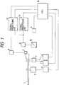
- Fig. 1 is a constitutional drawing to show an embodiment of a magneto-optical recording apparatus according to the present invention.
- reference numeral 1 designates a magneto-optical recording medium such as a magneto-optical disk to conduct recording and reproducing of information. A specific construction and properties of the recording medium will be detailed later.
- Numeral 2 denotes a spindle motor for rotating the recording medium 1; 3 a spindle servo for controlling to rotate the spindle motor 2 at a constant speed; 4 a light pickup for converging an optical flux from a light source 9 onto the recording medium 1; 5 a focusing servo for controlling to prevent focus offset of a light beam of the light pickup 4 relative to a medium surface of the recording medium 1; 6 a tracking servo for controlling to prevent offset of the light beam of the light pickup 4 relative to an information track on the recording medium 1; 7 a floating magnetic head for generating a magnetic field modulated depending upon information to be recorded; and 8 a magnetic head driver for driving the floating magnetic head 7.
- Numeral 9 designates a light source provided with a semiconductor laser as a light source and a drive circuit for turning on and off the semiconductor laser; 10 a polarized light beam splitter for separating a light returning from the optical pickup 4 (reflection light from the recording medium) from a light advancing from the light source 9 to the light pickup 4; 11 an RF sensor amplifier for receiving the light returning from the light pickup 4 after separated by the polarized light beam splitter 10 to reproduce the information recorded on the recording medium 1 as an electric signal; and 12 a signal processing circuit for detecting whether the information is correctly recorded based on the reproduction signal reproduced by the RF sensor amplifier 11 and on the recording information given to the floating magnetic head 7. Details will be later explained as to specific construction and operation of the signal processing circuit 12.
- Numeral 13 denotes a signal processing circuit for binarizing the reproduction signal reproduced by the RF sensor amplifier 11, and numeral 14 a CPU for totally controlling the spindle servo 3, the focusing servo 5, the tracking servo 6, the light source 9, the signal processing circuit 12, the signal processing circuit 13, and others as explained above.
- Fig. 2 is a circuit diagram to show a particular circuit example of the signal processing circuit 12 as shown in Fig. 1.
- reference numeral 15 denotes an encoder for modulating a recording signal sent from the CPU 14 to convert it into recording information suitable for recording in the recording medium 1; 16 a delay circuit for delaying the recording information produced by the encoder 15 for a constant time; and 17 a timing generator for producing a timing signal for reading a production signal (as will be referred to an RF signal) from the RF sensor amplifier 11, as later described in detail, based on the recording information produced by the encoder 15.
- Numeral 18 represents a first A/D converter for performing an A/D conversion of the RF signal with a signal of the timing generator 17 and holding a content thereof for a certain time; 19 a second A/D converter for performing an A/D conversion of the RF signal with a signal of the timing generator and holding a content thereof for a certain time; 20 a comparator for successively comparing the content held by the A/D converter 18 with the content held by the A/D converter 19; and 21 an error detector for judging whether the recording information thus recorded is correctly recorded on the recording medium 1 with outputs of the comparator 20 and of the timing generator 17.
- Fig. 3 is a drawing to show a specific construction of the magneto-optical recording medium 1 as shown in Fig. 1.
- numeral 22 denotes a first recording layer for storing information as a direction of magnetization by a magnetic field generated by the floating magnetic head 7 and by an optical flux converged by the light pickup 4.
- numeral 23 denotes a second recording layer for similarly storing information as a direction of magnetization with a mutual action of the light beam and the magnetic field and for causing the Kerr effect on the light beam radiated from the light pickup 4 based on the magnetization direction in the portion radiated by the light beam.
- first and the second recording layers 22, 23 show a relation between a temperature and a coercive force in the first and the second recording layers 22, 23, in which the first recording layer 22 has a lower Curie temperature than the second recording layer 23 and the second recording layer 23 has a greater coercive force than the first recording layer 22.
- the first and the second recording layers 22, 23 are structured such that respective magnetizations thereof are coupled by an exchange coupling force.
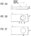
- Fig. 5 is a reason why the information presently recorded can be reproduced as a verification signal, which is a fundamental principle of the present embodiment.
- Fig. 5 let the light beam converged by the light pickup 4 move from the left to the right on the recording medium 1 as shown by an arrow in the drawing. Then, a relation between the light spot on the recording medium 1 and the Curie temperature of the recording medium 1 is as shown in Fig. 5B and Fig. 5C.
- an area represented by numeral 26 is one exceeding the Curie temperature of the recording medium 1 by the light beam converged by the light pickup 4 and a heat accumulation effect of the recording medium 1.
- the area 26 would appear only in the first recording layer 22.
- An area represented by numeral 27 is also one exceeding the Curie temperature of the first recording layer 22 and located within the light spot.
- an area represented by numeral 28 is one located within the light spot but having the first recording layer 22 not reaching the Curie temperature thereof, and an area represented by numeral 29 is one for reading the information in the recording medium 1 by the light pickup 4 using the Kerr effect of the optical flux converged.
- the region represented by numeral 27 is an area where the recording is now being carried out, in which a direction of magnetization is along the direction of the magnetic field generated by the floating magnetic head 7. Accordingly, once the magnetization direction in this area is confirmed to be correct according to the information which is currently being recorded, the verification may be effected.
- the state of magnetization in (b) in Fig. 6 is one at a time t1 as shown in Fig. 8, which will be explained later.
- the time t1 if an upward magnetic field greater than the coercive force of the second recording layer 23 and sufficiently smaller than the coercive force at the first recording layer 22 at an ordinary temperature is applied by the floating magnetic head 7, the area of the second recording layer 23 corresponding to the first recording layer 22 exceeding the Curie temperature has an upward magnetization oriented along the direction of the magnetic field of the floating magnetic head 7.
- the magnetization of the second recording layer 23 corresponding to the first recording layer 22 not exceeding the Curie temperature is oriented upward by the exchange coupling force with the first recording layer 22.
- the second recording layer 23 is not affected by the external magnetic field given by the floating magnetic head 7, and therefore the magnetization direction thereof is determined by the exchange coupling force with the first recording layer 22.
- the Kerr effect is caused in the optical flux in this state by the magnetization direction of the second recording layer 23 located in the light spot.
- the RF sensor amplifier 11 detects a direction and a magnitude of the Kerr effect, whereby a direction and a magnitude of magnetization of the second recording layer 23 located in the light spot may be detected and the information may be reproduced.
- the entire second recording layer 23 in the light spot has the upward magnetization at the time t1. A level of the RF signal reproduced by the RF sensor amplifier 11 is minimized in this state. If the entire second recording layer 23 in the light spot has a downward magnetization, the level of the RF signal becomes maximized.
- the first and the second recording layers 22, 23 are magnetized in the same process as above as shown in (c) in Fig. 6.
- the level of the RF signal becomes a little larger than that at the time t1.
- the first recording layer 22 and the second recording layer 23 where the temperatures thereof become lower than the Curie temperature of the first recording layer 22 are magnetized along the direction of the external magnetic field given by the floating magnetic head 7 at the time t1.
- the first and the second recording layers 22, 23 are oriented in a similar process as above in a direction corresponding to an information signal by the mutual action of the light beam and the magnetic field applied, overwriting new information on old information. Then, finally as shown in (m) in Fig. 7, an arrow-feather-like information pit (herein of downward magnetization) is recorded on the information track.
- an arrow-feather-like information pit herein of downward magnetization
- FIG. 9A and Fig. 9B show magnetization directions of the first and the second recording layers 22, 23 in correspondence with the respective information pits and reproduction signals reproduced therefrom.
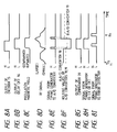
- Fig. 8A shows a recording signal output from the encoder 15 as shown in Fig. 2 to record the information pit as shown in Fig. 9B.
- the recording signal is a signal converted by the the encoder 15 as to be suitable for recording.
- the recording signal is output to the delay circuit 16 and is delayed therein for a predetermined time as shown in Fig. 8B. After the delay, the recording signal is output to the magnetic head driver 8 as shown in Fig. 1.
- the magnetic head driver 8 drives the floating magnetic head 7 based on the output signal of the delay circuit 16.
- the floating magnetic head 7 generates a magnetic field modulated depending upon the recording signal as shown in Fig. 8C to apply it to the recording medium 1.
- a light beam for recording is radiated from the light source 9 and is converged as a micro light spot as shown in Fig. 9A by the light pickup 4 on the recording medium 1.
- the light spot is in focusing control and in tracking control performed by the focusing servo 5 and the tracking servo 6 to scan over the information track of the magneto-optical recording medium 1 which is in a rotation state.
- the state. of magnetization in the recording medium 1 at the time t1 in Fig. 8 is the aforementioned one as shown in (b) in Fig. 6.
- a state at a time t24 corresponds to (l) in Fig. 7.
- the RF signal is taken into the A/D converters 18, 19 with timing signals of the timing generator 17 as shown in Fig. 2, and is held there.
- the timing signals are output as shown in Fig. 8E before and after the direction of the magnetic field of the floating magnetic head 7 changes, that is, at a leading edge and at a trailing edge of the recording signal as shown in Fig. 8B.
- the RF signal before the change of the magnetic field is taken into the A/D converter 18, and the RF signal after the change into the A/D converter 19.
- a time to hold the RF signal is a duration before each A/D converter takes a next RF signal.
- the RF signal thus held is shown in Fig. 8F, in which a letter A as shown by a solid line is a holding signal of the A/D converter 18 and a character B as shown by a broken line is a holding signal of the A/D converter 19.
- the respective signals held in the A/D converters 18, 19 are output to the next comparator 20, in which levels of the two signals are compared with each other. If a value of the A/D converter 18 is larger than that of the A/D converter 19, the comparator 20 outputs a high level signal as shown in Fig. 8G. Conversely, if the value of the A/D converter 19 is larger than that of the converter 18, a low level signal is output. In other words, the comparator 20 detects in view of a relation between the values of the two A/D converters 18, 19 whether the RF signal is in increase trend (a state in which the floating magnetic head is applying a downward magnetic field) or in decrease trend (a state in which the floating magnetic head is applying an upward magnetic field).
- the timing generator 17 produces a signal representing the direction of the magnetic field of the floating magnetic head 7 as shown in Fig. 8H, that is, a high level signal if the direction of the magnetic field of the floating magnetic head 7 is downward or a low level signal if it is upward, and then outputs it to an exclusive OR circuit 30 (as will be referred to as Ex. OR circuit). Then, the Ex. OR circuit 30 conducts an exclusive OR operation between the output of the comparator 20 and the signal from the timing generator 17 to detect match or mismatch of the two input signals. In this case, since the signal as shown in Fig. 8H output from the timing generator 17 to the Ex.
- OR circuit 30 is one to show which the direction of the magnetic field generated by the floating magnetic head 7 is, as described above, detected are the trend of increase or decrease of the RF signal reproduced by the RF sensor amplifier 11, and, match or mismatch of the RF signal with the direction of the magnetic field of the floating magnetic head 7. Accordingly, since the signal level of the RF signal is determined by the magnetization direction of the second recording layer 23 in the light spot, the output signal shows whether the change in magnetic field generated by the floating magnetic head 7 is correctly reflected on the second recording layer 23.
- a match or mismatch signal of the Ex. OR circuit 30 thus obtained that is, an exclusive OR signal between the two signals as shown in Fig. 8G and Fig. 8H, is output down to the error detector 21.
- the error detector 21 judges using the signal as shown in Fig. 8I whether misrecording of information is present or not, and outputs a result thereof to the CPU 14.
- the error judgement operation of the error detector 21 is explained in more detail.
- the timing generator 17 outputs the signal as shown in Fig. 8I to the error detector 21 to show that the magnetic field of the floating magnetic head 7 has been inverted and that respective RF signals in the inversion of the magnetic field have been taken into the A/D converters 18, 19, and to show that the respective A/D converters have held the signals.
- the signal keeps a high level for a certain time as shown in Fig. 8I, and the error detector 21 takes in the match or mismatch signal of the Ex. OR circuit 30 in the duration of the high level to detect an error based thereon.
- high level signals as shown in Figs. 8G and 8H are respectively input into the Ex. OR circuit 30, whereby the Ex. OR circuit 30 detects a match. The error detector 21 judges that the information is correctly recorded in this case accordingly.
- the high level duration of the signal output from the timing generator 17 to the error detector 21 as shown in Fig. 8I is a duration at most extended up to the next inversion of the magnetic field.
- the simultaneous verification with recording using a single light source i.e., the one beam direct verification may be effectively performed by detecting match or mismatch of the direction of the magnetic field generated by the magnetic head with a trend of increase or decrease of a level of the RF signal reproduced.
- accurate verification since the verification is not affected by a cross talk of old information included in the reproduction signal, accurate verification may be conducted free of influence of old information even if old information components are contained in the reproduction signal as seen in the conventional apparatuses.
- An error is detected in the above-described embodiment by the match or mismatch of the direction of the magnetic field of the magnetic head with the increase or decrease trend of the reproduction signal, while an error is detected in the present embodiment by a level of the RF signal.
- a level of the RF signal there exists in the recording layers in the light spot an area which is always influenced by the magnetic field of the magnetic head, and therefore the signal level of the RF signal is always influenced by the area.
- the RF signal becomes below a certain value if the magnetic field generated by the magnetic head is for example upward, while it becomes above the certain value if the generated magnetic field is downward.
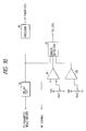
- Fig. 10 is a block diagram of the present embodiment, in which reference numeral 15 is an encoder and numeral 16 is a delay circuit, which are same as shown in Fig. 2.
- numerals 24, 25 denote comparators which compare a level of the RF signal with respective reference voltages set by variable resistors RV1, RV2. These reference voltages are set at respective constant voltages below and above the certain value, respectively, corresponding to the upward and downward magnetic fields generated as described above.
- the comparators 24, 25 compare the RF signal with the reference voltages, and output respective comparison results to an error detector 31.
- the verification is effected by comparing the detection result with the recording signal in the error detector 31.
- the error detector judges that the information is correctly recorded if the signal being presently recorded is coincident with the direction of the magnetic field. Otherwise, the detector 31 judges that an error occurs. Then the detector 31 informs the CPU 14 of the judgement result.
- the verification since the verification is carried out by the level of the RF signal, in addition to the advantages of the above first embodiment, another advantage may be enjoyed such that verification may be effective for a long pit in pit edge recording or the like.
- the present invention may enable the inspection as to whether the recording information is correctly written while carrying out the information recording.
- the apparatus according to the present invention may enjoy various merits and advantages such as a great progress in increase of recording speed as compared to the conventional apparatuses, simplification of structure of the light head with a, single beam spot, easy production of the apparatus without complicated optical adjustment of the light head, etc.
- a further advantage is accurate verification effected even in case of a reproduction signal including old information components, irrespective of a cross talk of the old information components.
Applications Claiming Priority (2)
| Application Number | Priority Date | Filing Date | Title |
|---|---|---|---|
| JP329824/91 | 1991-11-19 | ||
| JP3329824A JPH05144114A (ja) | 1991-11-19 | 1991-11-19 | 光磁気記録装置 |
Publications (3)
| Publication Number | Publication Date |
|---|---|
| EP0543580A2 true EP0543580A2 (fr) | 1993-05-26 |
| EP0543580A3 EP0543580A3 (en) | 1993-11-18 |
| EP0543580B1 EP0543580B1 (fr) | 1998-07-22 |
Family
ID=18225643
Family Applications (1)
| Application Number | Title | Priority Date | Filing Date |
|---|---|---|---|
| EP92310394A Expired - Lifetime EP0543580B1 (fr) | 1991-11-19 | 1992-11-13 | Appareil magnéto-optique capable de reproduire l'information enregistrée pendant l'enregistrement |
Country Status (4)
| Country | Link |
|---|---|
| US (1) | US5563851A (fr) |
| EP (1) | EP0543580B1 (fr) |
| JP (1) | JPH05144114A (fr) |
| DE (1) | DE69226333T2 (fr) |
Cited By (1)
| Publication number | Priority date | Publication date | Assignee | Title |
|---|---|---|---|---|
| EP0735532A3 (fr) * | 1995-03-28 | 1997-10-01 | Nippon Kogaku Kk | Méthode et commande d'enregistrement optique |
Families Citing this family (7)
| Publication number | Priority date | Publication date | Assignee | Title |
|---|---|---|---|---|
| JP3333613B2 (ja) * | 1993-12-07 | 2002-10-15 | 株式会社日立製作所 | 光情報記録媒体並びに光情報記録再生方法及び光情報記録再生装置 |
| JP2950181B2 (ja) * | 1995-02-16 | 1999-09-20 | 日本電気株式会社 | 光磁気ディスク記録装置 |
| JP2989575B2 (ja) * | 1997-12-12 | 1999-12-13 | 三洋電機株式会社 | 光磁気記録媒体 |
| US6618337B2 (en) * | 2000-01-28 | 2003-09-09 | Matsushita Electric Industrial Co., Ltd. | Information recording and reproduction apparatus |
| JP2005251240A (ja) * | 2004-03-01 | 2005-09-15 | Canon Inc | 光学的記録再生装置 |
| EP1912210A4 (fr) * | 2005-08-03 | 2009-01-14 | Fujitsu Ltd | Dispositif d'enregistrement et de reproduction d'informations optiques, et support d'enregistrement d'informations optiques |
| WO2007015299A1 (fr) * | 2005-08-03 | 2007-02-08 | Fujitsu Limited | Dispositif d’enregistrement et de reproduction d’informations optiques et support d’enregistrement d’informations optiques |
Family Cites Families (10)
| Publication number | Priority date | Publication date | Assignee | Title |
|---|---|---|---|---|
| JPH06105509B2 (ja) * | 1985-05-31 | 1994-12-21 | キヤノン株式会社 | 光磁気記録再生装置 |
| JP2574765B2 (ja) * | 1986-07-09 | 1997-01-22 | 株式会社日立製作所 | 光磁気デイスク装置 |
| KR910003039B1 (ko) * | 1987-01-26 | 1991-05-17 | 가부시기가이샤 히다찌세이사꾸쇼 | 정보의 기록 재생 방법 |
| JPH01165056A (ja) * | 1987-09-21 | 1989-06-29 | Sharp Corp | 光情報記録再生装置 |
| US5233578A (en) * | 1988-12-28 | 1993-08-03 | Canon Kabushiki Kaisha | Method of recording information on a recording medium having at least two magnetic layers |
| JPH0373448A (ja) * | 1989-05-10 | 1991-03-28 | Ricoh Co Ltd | 光磁気記録方法 |
| CA2026740C (fr) * | 1989-11-20 | 1995-08-29 | Morovat Tayefeh | Lecture de l'information enregistree anterieurement durant l'enregistrement ou l'effacement d'un support magneto-optique |
| JP2574911B2 (ja) * | 1990-01-10 | 1997-01-22 | シャープ株式会社 | 光磁気記録方法 |
| EP0818783A3 (fr) * | 1991-07-16 | 1999-04-14 | Canon Kabushiki Kaisha | Milieu d'enregistrement magnétooptique et méthode |
| JPH0520720A (ja) * | 1991-07-16 | 1993-01-29 | Canon Inc | 光磁気記録方式 |
-
1991
- 1991-11-19 JP JP3329824A patent/JPH05144114A/ja active Pending
-
1992
- 1992-11-09 US US07/973,757 patent/US5563851A/en not_active Expired - Fee Related
- 1992-11-13 EP EP92310394A patent/EP0543580B1/fr not_active Expired - Lifetime
- 1992-11-13 DE DE69226333T patent/DE69226333T2/de not_active Expired - Fee Related
Cited By (2)
| Publication number | Priority date | Publication date | Assignee | Title |
|---|---|---|---|---|
| EP0735532A3 (fr) * | 1995-03-28 | 1997-10-01 | Nippon Kogaku Kk | Méthode et commande d'enregistrement optique |
| US5684765A (en) * | 1995-03-28 | 1997-11-04 | Nikon Corporation | Optical recording method and control |
Also Published As
| Publication number | Publication date |
|---|---|
| US5563851A (en) | 1996-10-08 |
| DE69226333T2 (de) | 1998-12-03 |
| EP0543580B1 (fr) | 1998-07-22 |
| JPH05144114A (ja) | 1993-06-11 |
| EP0543580A3 (en) | 1993-11-18 |
| DE69226333D1 (de) | 1998-08-27 |
Similar Documents
| Publication | Publication Date | Title |
|---|---|---|
| US4472748A (en) | Method of processing information signal with respect to opto-magnetic record medium | |
| EP0552936B1 (fr) | Appareil et procédé pour l'enregistrement d'un milieu optique | |
| JP2655682B2 (ja) | 光磁気情報記録再生装置 | |
| US5060208A (en) | Magnetooptical recording method and apparatus utilizing shift adjustment | |
| JP2559372B2 (ja) | 光ディスク装置及び光情報記録方法 | |
| EP0430811B1 (fr) | Appareil de reproduction de signaux, utilisant l'effet magnéto-optique | |
| JP2574765B2 (ja) | 光磁気デイスク装置 | |
| JPH04258831A (ja) | 光磁気ディスクの再生方法 | |
| US6249490B1 (en) | Magneto-optical recording/reproducing method and apparatus | |
| JPH08221911A (ja) | 光磁気ディスク記録装置 | |
| US5563851A (en) | Magneto-optical recording apparatus capable of reproducing recording information while recording | |
| JPH07118106B2 (ja) | 光磁気記録再生装置 | |
| JPH0276144A (ja) | 光記録装置 | |
| EP0220023B1 (fr) | Dispositif de mémoire magnéto-optique | |
| US6075762A (en) | Disc drive apparatus | |
| JPH0777048B2 (ja) | 記録媒体駆動装置 | |
| JP2588503B2 (ja) | 光磁気デイスクの再生装置 | |
| JP2589317B2 (ja) | 光ディスク記録再生装置 | |
| JP2935375B2 (ja) | 光磁気記録再生装置 | |
| JP2613921B2 (ja) | 光磁気メモリ装置 | |
| JPH0765379A (ja) | 情報記録装置 | |
| JP2667678B2 (ja) | 光磁気メモリ装置 | |
| JPH05174502A (ja) | 情報記録装置 | |
| JPS6254857A (ja) | 光磁気情報記録装置 | |
| JPH11126388A (ja) | データ記録方法及びデータ記録装置 |
Legal Events
| Date | Code | Title | Description |
|---|---|---|---|
| PUAI | Public reference made under article 153(3) epc to a published international application that has entered the european phase |
Free format text: ORIGINAL CODE: 0009012 |
|
| AK | Designated contracting states |
Kind code of ref document: A2 Designated state(s): DE ES FR GB IT NL |
|
| PUAL | Search report despatched |
Free format text: ORIGINAL CODE: 0009013 |
|
| RHK1 | Main classification (correction) |
Ipc: G11B 11/10 |
|
| AK | Designated contracting states |
Kind code of ref document: A3 Designated state(s): DE ES FR GB IT NL |
|
| 17P | Request for examination filed |
Effective date: 19940411 |
|
| 17Q | First examination report despatched |
Effective date: 19951110 |
|
| GRAG | Despatch of communication of intention to grant |
Free format text: ORIGINAL CODE: EPIDOS AGRA |
|
| GRAG | Despatch of communication of intention to grant |
Free format text: ORIGINAL CODE: EPIDOS AGRA |
|
| GRAG | Despatch of communication of intention to grant |
Free format text: ORIGINAL CODE: EPIDOS AGRA |
|
| GRAH | Despatch of communication of intention to grant a patent |
Free format text: ORIGINAL CODE: EPIDOS IGRA |
|
| GRAH | Despatch of communication of intention to grant a patent |
Free format text: ORIGINAL CODE: EPIDOS IGRA |
|
| GRAA | (expected) grant |
Free format text: ORIGINAL CODE: 0009210 |
|
| AK | Designated contracting states |
Kind code of ref document: B1 Designated state(s): DE ES FR GB IT NL |
|
| PG25 | Lapsed in a contracting state [announced via postgrant information from national office to epo] |
Ref country code: NL Free format text: LAPSE BECAUSE OF FAILURE TO SUBMIT A TRANSLATION OF THE DESCRIPTION OR TO PAY THE FEE WITHIN THE PRESCRIBED TIME-LIMIT Effective date: 19980722 Ref country code: IT Free format text: LAPSE BECAUSE OF FAILURE TO SUBMIT A TRANSLATION OF THE DESCRIPTION OR TO PAY THE FEE WITHIN THE PRE;WARNING: LAPSES OF ITALIAN PATENTS WITH EFFECTIVE DATE BEFORE 2007 MAY HAVE OCCURRED AT ANY TIME BEFORE 2007. THE CORRECT EFFECTIVE DATE MAY BE DIFFERENT FROM THE ONE RECORDED.SCRIBED TIME-LIMIT Effective date: 19980722 Ref country code: ES Free format text: THE PATENT HAS BEEN ANNULLED BY A DECISION OF A NATIONAL AUTHORITY Effective date: 19980722 |
|
| REF | Corresponds to: |
Ref document number: 69226333 Country of ref document: DE Date of ref document: 19980827 |
|
| ET | Fr: translation filed | ||
| NLV1 | Nl: lapsed or annulled due to failure to fulfill the requirements of art. 29p and 29m of the patents act | ||
| PLBE | No opposition filed within time limit |
Free format text: ORIGINAL CODE: 0009261 |
|
| 26N | No opposition filed | ||
| REG | Reference to a national code |
Ref country code: GB Ref legal event code: IF02 |
|
| PGFP | Annual fee paid to national office [announced via postgrant information from national office to epo] |
Ref country code: GB Payment date: 20031030 Year of fee payment: 12 |
|
| PGFP | Annual fee paid to national office [announced via postgrant information from national office to epo] |
Ref country code: FR Payment date: 20031125 Year of fee payment: 12 |
|
| PGFP | Annual fee paid to national office [announced via postgrant information from national office to epo] |
Ref country code: DE Payment date: 20031126 Year of fee payment: 12 |
|
| PG25 | Lapsed in a contracting state [announced via postgrant information from national office to epo] |
Ref country code: GB Free format text: LAPSE BECAUSE OF NON-PAYMENT OF DUE FEES Effective date: 20041113 |
|
| PG25 | Lapsed in a contracting state [announced via postgrant information from national office to epo] |
Ref country code: DE Free format text: LAPSE BECAUSE OF NON-PAYMENT OF DUE FEES Effective date: 20050601 |
|
| GBPC | Gb: european patent ceased through non-payment of renewal fee |
Effective date: 20041113 |
|
| PG25 | Lapsed in a contracting state [announced via postgrant information from national office to epo] |
Ref country code: FR Free format text: LAPSE BECAUSE OF NON-PAYMENT OF DUE FEES Effective date: 20050729 |
|
| REG | Reference to a national code |
Ref country code: FR Ref legal event code: ST |